1
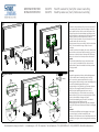
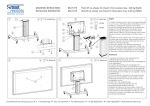
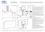
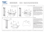
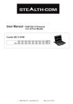
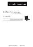
C
MOUNTING INSTRUCTIONS
INSTALLATIE INSTRUCTIES
1
DGa80x35 (4x) DG 80x35
2 (4x)
a
C
062.7270
062.7270 D
2
F
F
b
b
c
c
c
c
d
d
Floor lift on wheels for (touch-) flat screens max. 120 kg
Vloerlift op wielen voor (touch-) flatscreens max. 120 kg
D
A
B
b
b
M8x25
M8x25(4x)
(4x)
c
c
M8M8
(8x)
(8x)
d
d
M8M8
(4x)
(4x)
H H
F
F
G
G
E
a
E
C C
a
English
1. Fasten the lifting column (A) on the wheel frame(B)
in such a way, that the position of the lifting column
cable (C) corresponds as shown in the figure.
2. Mount the stand head (D)( part for mounting the
display) on the lifting column. Run lifting column
cable (C) through the cable transit in the stand
head. Attach cable (C) to the supplied motor cable
(E) and connect it with entrance 1 of the control
box.
3. Fasten two M8 x 16 bolts in the two upper holes at
the back side of the display. Keep enough distance
between the bolt’s head and the back side of the
display for the following step.
4. Hang the display in the head by sticking the
bolts in the keyholes and lowering them. Fasten the
display according its VESA pattern, by mounting the
remaining two bolts in the display via the back side
of the head. Following fasten all bolts in the display.
Nederlands
3
e
e
e
M8x16
(2x)
4 (2x)
M8x16
4
f
e
f
f
f
M8x16
M8x16(2x)
(2x)
1. Bevestig de hefkolom (A) zodanig op het
wielframe (B) dat de positie van de
hefkolomkabel (C) overeenkomt zoals weergegeven
in de afbeelding.
2. Monteer de statiefkop (D) (onderdeel t.b.v.
montage van het scherm) op de hefkolom. Voer de
hefkolomkabel (C) via de doorvoer in de statiefkop
naar boven. Verbind kabel (C) met de bijgeleverde
motorkabel (E) en sluit deze aan op ingang 1 van de
controlbox (F).
3. Draai twee M8 x 16 bouten in de twee bovenste
gaten aan de achterzijde van het scherm. Houd
voldoende ruimte over tussen de boutkop en de
achterzijde van het
scherm t.b.v. de volgende stap.
4. Hang het scherm aan de kop door de
gemonteerde boutkoppen door de
slotgaten te steken en te laten zakken. Fixeer het
scherm conform het VESA patroon, door de overige
twee bouten via de achterzijde van de kop in het
scherm te monteren. Vervolgens alle vier bouten in
het scherm aandraaien.
SmartMetals Mounting Solutions B.V. • Handelsweg 4 • 4231 EZ Meerkerk • The Netherlands • T +31(0)183352942 • F +31(0)183352909 • E [email protected]
MOUNTING INSTRUCTIONS
INSTALLATIE INSTRUCTIES
5
a
2
DG 80x35 (4x)
062.7270
062.7270 D
6
F
Floor lift on wheels for (touch-) flat screens max. 120 kg
Vloerlift op wielen voor (touch-) flatscreens max. 120 kg
b
M8x25 (4x)
c
M8 (8x)
d
M8 (4x)
b
c
H
c
F
d
G
C
E
E
a
up
7
e
Optional / Optioneel
M8x16 (2x)
down
4
f
I
g
M6x16
(2x)
M8x16
(2x)
h
M6 (2x)
g
h
h
063.7260
g
5. Determine the preferred position of the control panel (G),
at for example the bottom side of the display. Make sure
that the panel location is free from dust and grease. Peel
the upper layer from the double-sided tape and press the
control panel firmly to the display. After 24H the fastening of
the tape is optimal, until that time burden as little as
possible. Connect the cable of the control panel via one of
the cable transits with the control box.
Following connect the power cable (H) with the wall socket
(230V). Look at schematic image of step 4 for more
information.
6. Bundle the cables of the display, the motor cable, power
cable and the control panel cable according to your own
preferences, at the back side of the head with Tie Wraps.
Please note: unit must be in lowest position when moved
Optional
7. Position the lockable lid as shown and make sure the
tips (I), on top of the lockable lid, fit into the two slots of
the stand head. Fasten the lockable lid with the provided
mounting material.
Nederlands
I
e
English
f
5. Bepaal de gewenste positie van het bedieningspaneel
(E), bij voorbeeld aan de onderzijde van het scherm.
Zorg er voor dat de gewenste positie stof en vetvrij is.
Pel vervolgens de bovenste laag van de dubbelzijdige tape
af en druk het bedieningspaneel stevig aan.
Na vierentwintig uur is de hechting van de tape optimaal,
tot die tijd zo min mogelijk belasten! Sluit tevens het
kabeltje van het bedieningspaneel via een van de
doorvoeren (kabels) op de controlbox aan en sluit de
netstroom kabel (H) aan op een wandcontactdoos (230V).
Zie ook de schematische weergave bij stap 2.
6. Bundel de bekabeling van het scherm, motorkabel,
netstroom kabel en het kabeltje van het
bedieningspaneel naar eigen inzicht, aan de achterzijde
van kop met Tie Wraps. Verplaats de lift alleen in de laagste
positie!
Optioneel
7. Positioneer de afsluitkap zoals weergegeven en zorg er
voor dat de lipjes (I), aan de bovenzijde van de
afsluitkap, in de twee sleuven van de statiefkop komen. Zet
de afsluitkap vervolgens vast met meegeleverde montage
materiaal.
SmartMetals Mounting Solutions B.V. • Handelsweg 4 • 4231 EZ Meerkerk • The Netherlands • T +31(0)183352942 • F +31(0)183352909 • E [email protected]