1
ALIGN
SGX Flybarless System
INSTRUCTION MANUAL
E An YE
HEG3GX01T
Compact
; 7 YA N
Intelligence ! Technology! Deftness !
[Bais] (mews) (12bit] ( Aps) (42) (5.8uS) (o<) (Easy) [energy stabid а, J (GOV) (6%) 72.) (RoHs)
Please read this manual carefully before assembling.
1m | INTRODUCTION We recommend that you keep this manual for future
= reference regarding tuning and maintenance.
1-2 | 28." —
3-14 | SCX FLYBARLESS FL760 MANUAL ENE RZ AYASHOEHS BHR IEEE DER
3GX SETUP TABLE NECESITE > SOJSE PASES + TEIDE ZA > am EA
| moses TRAE - 105-— TENCIA MEL LEMZERE
6-17 | Rees | EAS LUFRORSE -
17 FLIGHT ADJUSTMENT AND SETTING
MATE Ed ARTE
90 3GX FLYBARLESS FLIGHT TEST PROCEDURE Compatible with helicopter of all sizes from T-REX 250 to T-REX 800
RATA EAE 3GX Flybarless. Here we use T-REX 800 as an example.
” TROUBLESHOOTING !
Fe AT PASE HE BR 3GX Flybarless EF BEES) AESRE ANE S#T-REX 250 ~T-REX800 -
27 ne TE NC EPIA T-REX 800165731217 88 9) -
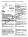
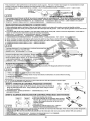
1. INTRODUCTION is ALIGN
7
Thank you for buying ALIGN Products. The 3GX Flybarless System is designed as an easy to use, . Please read the manual
carefully before assembling the model, and follow all precautions and recommendations located within the manual. Be sure
to retain the manual for future reference, routine maintenance, and tuning. The 3GX Flybarless System is a new product
developed by ALIGN, providing flying stability for beginners, full aerobatic capability for advanced fliers, and unsurpassed
reliability for customer support.
DEN‘ A Aa В НОГЕ РЗС ХЛЕЗЕНА ВЕ ЛА > БЫ МЛ ОРЛ ВО) В ай ANSEHEN’ dies > ай
BRE > FA O SETE RENNES - IGXE FEE ANTE BOLETA ENE ' TAE ERRE EINEN DE EEE RENTES
E + IKE GEARS EME ENEE ©
WARNING LABEL LEGEND £x=Z=
CN FORBIDDEN | | Do notattempt under any circumstances.
= Ib FEET | > ES EEE -
| AN Mishandling due to failure to follow these instructions may resultin damage or injury.
= = A] 7 UE ES RF EN DN > MIR AOS ER TRISTE AE -
A CAUTION Mishandling due to failure to follow these instructions may resultin danger.
ZE e AA 9 Ве ЕВА ВВ › ПО КР ЯВ з6 88 ЭГ ВЕзе MISA ©
IMPORTANT NOTES =æ=2=œ
R/C helicopters, including the are not toys. R/C helicopter utilize various high-tech products and technologies to provide
superior performance, Improper use of this product can result in serious injury or even death. Please read this manual
carefully before using and make sure to be conscious of your own personal safety and the safety of others and your
environment when operating all ALIGN products. Manufacturer and seller assume no liability for the operation or the use of
this product. This productis intended for use only by adults with experience flying remote control helicopters at a legal flying
field. After the sale of this product we cannot maintain any control over its operation or usage.
As the user of this product, you are solely responsible for operating it in a manner that does not endanger yourself and others
or result in damage to the product or the property of others.
ETE FREE + CE JH San kA] HUREN IEE ESRBREES ERIN ' В РВ 57 6156
DEF SS’ DEAL a! KEANE Saale HESSEN 2
HEEE : $002 EN AS ASESESKEUSZERTERNT‘’ MERKRZEETKFER
DS BEER ARTE EIER HZ *
BRFERNERE f REE-HREECERENRERTRAREHNEIZA °
We recommend that you obtain the assistance of an experienced pilot before attempting to fly our products for the first time.
À local expert is the best way to properly assemble, setup, and fly your model for the first time. The 3GX Flybarless System
requires a certain degree of skill to operate, and is a consumer item. Any damage or dissatisfaction as a result of accidents or
modifications are not covered by any warrantee and cannot be returned for repair or replacement. Please contact our
distributors for free technical consultation and parts at discounted rates when you experience problems during operation or
maintenance. As Align Corporation Limited has no control over use, setup, final assembly, modification or misuse, no liability
shall be assumed nor accepted for any resulting damage or injury. By the act of use, setup or assembly, the user accepts all
resulting liability.
RUBRERESRERWERBREE ZEH®D WiEFRERR TEMASFEREFHIERE - EOL AIAA PSSS EAN ARENA
AERO WERFEN’ ZIELE ER «- FEST HERS - НЕ АВ ВОЕН АЯ + EE + 186 8
À ER FA RATS LORI IES Ranas © НЕО ИВ АВ > 32 ~ 8% ~ BX ~ RIFA E ATISALOJRIE > SNE - ERE EMI
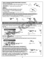
2. SAFETY NOTES 2<:+==6 ALIGN
ENEE
| AT |
- Fly only in safe areas, away from other people. Do not operate R/C aircraft within the vicinity of homes or crowds of people.
R/C aircraft are prone to accidents, failures, and crashes due to a variety of reasons including, lack of maintenance, pilot
error, and radio interference. Pilots are responsible for their actions and damage or injury occurring during the operation
or as of a result of R/C aircraft models.
- Prior to every flight, carefully check rotorhead spindle shaft screws and tail blade grip screws, linkage balls and screws,
ensure they are firmly secured.
ERRE ARES CRTR RITEHELERAS ABBEAESIHGEE EFEHRHEAR DIRFEELHANRE - SORA
TAREAS DRAE BRTESHBLIBRTEZZ UR THEBERBMSEMTABIHNZIEIT -
- ENOMRTENA (510185 - ENEE EEN > ENEE ZN LIRE SEM > A > ER LIS SAA REN EMT»
[Q"2""] LOCATE AN APPROPRIATE LOCATION its R Az
R/C helicopters fly at high speed, thus posing a certain degree of potential danger.
Choose a legal flying field consisting of flat, smooth ground without obstacles. Do
not fly near buildings, high voltage cables, or trees to ensure the safety of yourself,
others and your model. For the first practice, please choose a legal flying field.
Do not fly your model in inclement weather, such as rain, wind, snow or darkness.
BRURCNAS FORE SHOOBEESHEY * SRONSLENQEE - BRUTHUER
ISAEER TARRO - ADÉÉTORS SENTE MDATRAESREA Bi EE
7 BEER BASS ERRENNÉENE CRE ANENAE -
ВОЛЕ КО ВЕНА КЕ, МВК В НЕО -
QF | NOTE ON LITHIUM POLYMER BATTERIES X3t}*#sE
Lithium Polymer batteries are significantly more volatile than alkaline or Ni-Cd/Ni-
MH batteries used in RC applications. All manufacturer's instructions and warnings
must be followed closely. Mishandling of Li-Po batteries can result in fire. Always
follow the manufacturer's instructions when disposing of Lithium Polymer batteries.
i 2 EIR — AR ERC {FE ABUT E510 > ÍA E > EEC EEE E В 3705 8 В) > cate ¡E
EME 2 ERAIREIR - MOS EEE - JESSE EMMEZE - IDAS |
[Qn] PREVENT MOISTURE SR
RIC models are composed of many precision electrical components. Itis critical to
keep the model and associated equipment away from moisture and other
contaminants. The introduction or exposure to water or moisture in any form can
cause the model to malfunction resulting in loss of Use, or a crash. Do not operate
or expose to rain or moisture.
BREAN EHF HER FEN FREI
ER + BILKEEARS NEST LIFE SEA
QF] PROPER OPERATION 77ER
Please use the replacement of parts on the manual to ensure the safety of
instructors. This productis for R/C model, so do not use for other purpose.
BIS GAEMI: EONARNENES: BEMTMLESSRPWEL - NEMIEMÍZE -
BERREGRANEE AZABER - AZARES ASHACIABE
| A\VARNING| OBTAIN THE ASSISTANCE OF AN EXPERIENCED PILOT 35ER
Before turning on your model and transmitter,check to make sure no one else is
operating on the same frequency. Frequency interference can cause your model,
or other models to crash. The guidance provided by an experienced pilot will be
invaluable for the assembly, tuning, trimming, and actual first flight or unforeseen
danger may happen. (Recommend you to practice with computer-based flight
simulator.)
ZI MR + SMS SO RENNES ESE ART + 27869 6X18/0)5A 3695551 2510 EN Eo
e A Ве EMPERO ESSE ENS - EME SEE E
1 Е ВОВ) АСЕЕВ! ОО НИЕ Ле SENSORES OTRAS E E - (MARES
HERE AARON)
LAA“ SAFE OPERATION LE
Operate this unit within your ability. Do not fly under tired condition and improper
operation may cause in danger. Never take your eyes off the model or leave it
unattended while it is turned on. Immediately turn off the model and transmitter
when you have landed the model.
AFECENARTE —ERNBENRFSOR ANE ARNES ~ MAMET ASRIF EUREM
М8 ле) ОЛ ВЕ 8 Ве тво POTTER EEE + 136058 A CAE AER as En ©
IAE | ALWAYS BE AWARE OF THE ROTATING BLADES jéätæ##cpæ{t
During the operation of the helicopter, the main rotor and tail rotor will be spinning
at a high rate of speed. The blades are capable of inflicting serious bodily injury
and damage to the environment. Be conscious of your actions, and careful to
Keep your face, eyes, hands, and loose clothing away from the blades. Always fly
the model a safe distance from yourself and others, as well as surrounding objects.
EENIRRARNREBRELSHE TET AEHE TORRE EHEC RAE SE ЗОВ
E COREA AEREO REZAENE LRSTEERDETENTAREE -
| AAN KEEP AWAY FROM HEAT EA
R/C models are made of various forms of plastic. Plastic is very susceptible to
damage or deformation due to extreme heat and cold climate. Make sure not to
store the model near any source of heat such as an oven, or heater. Itis best to
store the model indoors, in a climate-controlled, room temperature environment.
EERE - E ABS EE PA MEDIR O - E-Bom EZME AZ EEE > OE» Ll
JE E Sm MEA EE SA RIE A OTE -
2
3.3GX FLYBARLESS MANUAL dc ES DA ALIGN
7
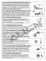
FEATURES Eme
[Axis] J-axis gyroscopic flybarless system to simulate the stability of mechanical flybar system, yet at the same time achieving
—— agile 3D performance.
390 PEL IBE EERE AM ERE FON RAMO TENE > PS EENISDIER: -
Utilizes MEMS gyro sensors, which feature small footprint, high reliability, and excellent stability.
EE RAMEMS ( Micro Electro Mechanical Systems) M8 E 2762008837 AB TRES BEE -
Sensor with 12 bit ultra high resolution, resulting in highly precise controls.
RoAJes1 21777 > REMATE MINE EE -
supports APS Gyro.
=2 AP SII E ©
Supports Spektrum and JR satellite receivers.
ZESPEKTRUME JRE 2 FF -
=
m
=
№.
al
=.
©
Supports Futaba S.Bus architecture.
(5.805) Futaba S.BUSIHEE ©
[<>] Software upgradable through PC interface adapter.
AB IHRE TEE ET -
[Easy] Simplistic setup process without the need of external devices. Setup is done through 5 steps and 2 sensitivity adjustments.
SEE EEE ARE - MIE UE de EEN 9] 75 БК РТВ Е >
Flybarless system dramatically improves 3D power output and efficiency, resulting in reduced fuel or electricity consumption.
WME RM JABEIESDAEMERITERE ERE EHREFEBE ANE NE LEE BIAS ВАХ 98 7) ®
stable] Highly sensitive gyroscopic sensors combined with advanced control detection routine providing higher hovering and
aerobatic stability than other flybarless system. ]
SREMRRTASRBRAERBERE TRH RTERAMBENB ER BERBER -
Suitable for all CCPM and mechanical mixing system.
8 TSE 10 [EAN ETE TÍ, — (a) AR S:C CPMZA SES EN FAN >
e El
Builtin speed governor function.
GOV
РОЖЕ ЛЕ 281) ВЕ ©
Sona Comaptible with helicopter of all sizes from T-REX 250 to T-REX 800.
250-800) 3G X FlybarlessEF DEHN ESHE AH ES#T-REX250~T-REX800 -
| ea | Capable to operate between 3.5V to 8.4V, compatible with high voltage servos.
=" ¡SE M3.5/-8.4V : TES TEER -
[aña] Small footprint, light weight, minimalists and reliable design.
— HO) - EE MSME OÍ TER Sra DIRA SEER -
[RoHS] RoHS certified.
NSROHSE BRE -
3GX FLYBARLESS SETUP INDICATORS mex 2571808
FLYBARLESS SYSTEM SETUP MODE # #32 Aa EEN
HR Che Os Y | ое Ne
Q ® © © ON (AL) © of
ve:
3 |< DR Te (EE y
Direct mode bypassing gyro, Collective mixing type Elevator reverse settings Aileron endpoints settings Aileron reverse settings
for mechanical travel a recognition and elevator HEM FR OT SETI ETE =| Efe OE
neutral point setup. endpoint settings
SM TAZA PI GAR E ¡ET PEO A MENO ATADOS E
RUDDER GYRO SETUP MODE РЕЛЕ ER
Anti-torque compensation
- — E eT ELE e SI sine
lo. 0-2
$e! 229, T
Q Gol
2 ELEY
Servo frame rate settings Digital/Analog Rudder Servo Reverse Rudder endpoints Rudder servo delay, and Anti-torque compensation
(1520 4 s and 7605) servo settings settings settings helicopter size settings settings
381520 и 5 ЕВ BL ALCOR 2550% TE BEP LEN DEE ВЕЕТ НЕВЫ ХЕ ri ERE RAODABIERORE
760 y SIR 3502 1E Ber ost
SETUP PRE-CHECK &ErZESHR
AE | While using 3GX FBL system, be sure to turn off the following functions in the transmitter
ERG REE EEE 5) ВЕН 55 22) В ВАД ВЕ
| % Swash Ring % Linkage Compensation % Swash Mix * Mixing * Acceleration
1. Connect the receiver and servos to the flybarless control unit as per diagram found on page 4—5.
2. Digital servos must be used on cyclic to avoid damage to servos.
commended servo spec: minimum speed 0.08 sec/60, torque 12kg.cm or higher.
3. The trim must be zero when using 3GX, and should not be adjusted at anytime. If the helicopter hovering tend to one side, it
means the swashplate doesn’t keep horizontal when setting. Go to flybarless system "Direct mode A gyro, for
mechanical travel and neutral point setup" to adjust the level of the swashplate and then re-complete the setup.
4. When the 3GX Flybarless system is installed for the first time, a few simple setup steps and fly tests need to be performed in the
flybarless setup mode. these steps need fo be performed only during initial setup, and does not need to be repeated for sub-se
quent flights. Just power up the system normally, check the proper servo operations, and fly. The initial setup procedure only
need to be repeated after software upgrade, pitch range reset, or subtrims are added in the transmitter.
1. EE ROLE STE SEE (HSE 4 SE) -
2. HF ES ENTDIRE * SESEROREER - RARE : RE0.08/0/60° DPI : #A7712kg.CmDLE -
3 E LENA ANIMES ROBTIBENMIE SEA REEEROEE8 « ERRER FERRITE + EEE ESA ET
BEDIBRE" BE+THSKTE BFENRE -
4. E—NEEIOX Flybarless BPHRAHT » WEEABLERGEED $TYEESNLEREERTIR, TREATABLE ALREETR RBEEH
№ › SORA FEEGNORO : FIEBRE BINRIENE SHERRIE (sub.trim)ls » WEBER ERI EIRET ERAT -
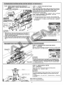
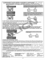
3GX CONNECTIVITY METHOD 36Xi£i475 1
METHOD 1:STANDARD RECEIVER CONNECTIVITY METHOD 5H— 683
| на A ILE dl 1. Connect all wires as shown in diagram. Receiver and 3GX
э aa |ELE "E | wires are color coded to distinguish the different connection
3 [==.]|PIT me = channels. Care should be taken to ensure proper wire color to
of CLE a UD = channel connection.
; === T HR-Purle 5: 2. While using the speed controller that not including BEC, you need
plas], GOV to connect the BEC power with 3GX "BATT" port.
3. Receiver power is achieved by connecting the 3GX "S.BUS/BIND"
port to the ch? or BATT port on receiver using supplied signal wire.
4. To avoid damage to servos, only digital servos should be used for
swashplate. Recommended spec: 0.08s/60 or faster, with 12 Kg
or higher torque.
5. 3GX has built in speed governor function which can be utilized by
purchasing the optional speed sensor. Governor setting is done
through channel 7 on the receiver.
1. BEBE TGET ER ТЕЩИ 38 93 С ХВ EAT ENÉRES RED AE
00 > FER ÓFOS ES O PROS PTEJMOD ELE -
2. 2 НЕВЕСТ DONDE: ash, /23R7CO3GXE) BATT SL LZABECE ©
| A E | 3. Е Кое К САНА НО ВОВА MAREO XE"S.BUS/BIND"U TEA CA
Cl = el La
Do not exchange AIL 4. +FRIUBZEH{UCIRES - SHE SHaRRIRE -
and PIT connections. | Battery | 00.000 31848 : Е [0.09060 7 : 187712kgl E
AILEPITATI EER © eE —+JL | BATT our 5. GX REESE REE ERSBRAISK TH » ENE a EEN 250
— _ -_-_—
| METHOD 2: FUTABA S.BUS CONNECTIVITY METHOD 5X: Futaba S.BUSIEEE
. For Futaba S.BUS receivers, connect wires as shown in diagram.
. While using the speed controller that not including BEC, you
need to connect the BEC power with 3GX "BATT" port.
. Receiver power is supplied through S.BUS signal wire connected
to 3GX's "S.BUS/BIND” port.
. The default channel/function mapping when using S.BUS are:
(1)AIL (2)ELE (3)THR (4)RUD (5)GAIN (6)PIT (7)GOV
S.BUS 1. El6S.BUSTEENFutabats35 - EE ENTER -
2. PAEBECK) 1071052 05,5 259 3GXA"BATT"3LITEABECEA -
3. ENS EF HOMSs.BUS MERIEZE3OCXY"S.BUS/IBIND" 3 ©
4. ES.BUSTIJEEN > PIENEE CIA y +
(1)AIL (2)ELE (3)THR (4)RUD (5)GAIN (6)PIT (7)GOV
| ANERUTION |
¡=> =
- If channel (3) Is set as PIT and channel (6)set as THR on transmitter,
THR RUD PIT ELE AIL Such as 8FG, 12Z, 14MZ, and etc, please reprogram the transmitter
ESC to utilize channe (3) as THR and channe (6) as PIT.
т & FTE FBYE REE EMETE(3)BERPIT (6):&)8/3 THRET + HINI8FG - 12Z -
= 1 14MZS ‘BP OE RSS PA) E m3) THR (6858 PIT -
5. To avoid damage to servos, only digital servos should be used
for swashplate. Recommended spec: 0.08s/60 or faster,
: * \ with 12Kg or higher torque.
eN 6. 3GX has built in speed governor function which can be utilized by
CAUTION purchasing the optional speed sensor.
ZA + = | Governor setting is done through channel 7 on the receiver.
5. += MNAE NOIR Sa|ES NOIR +
TD “FR FR JSON isis moose 5 : Amia
АЛ РИО Я © 6. a” EEE EEE НИ)
a 5 =
Ens 1
(sc,
METHOD 3: JRISPEKTRUM SATELLITE CONNECTIVITY METHOD %5=1=:JR/SPEKTRUMBE XRO |
1. For JR or Spektrum satellite receivers, connect wires as
shown in diagram.
2. While using the speed controller that not including BEC, you
need to connect the BEC power with 3GX "BATT "port.
3, To avoid damage to servos, only digital servos should be
used for swashplate. Recommended spec: 0.08s/60 or faster,
with 12Kg or higher torque.
4. 3GX has built in speed governor function which can be
utilized by purchasing the optional speed sensor. Governor
setting is done through channel 7 on the receiver. Channel
5/GEAR controls RPM of speed governor, channel 7/4 UX2
controls rudder gyro gain.
THR RUD PIT ELE AIL For radios with less than 6 channels, please use the standard
poser, anf receiver connectivity method.
es (es e e (e 5. For radios with less than 6 channels, channel 5/GEAR is used
Y E E в
po Mm E | for rudder gyro gain. Speed governor cannot be used. For
Te | safety concern, two satellite receives should be used, with
| each antenna perpendicular (90 degrees) from each other. А
— | || satellite receiver should be installed on each side of the
AN ESC Al OU ICO ) frame, separate by minimum distance of 5cm.
| * | + OOS o 6. Should both satellite receivers loose connectivity during flight,
Do not exchange AIL | 0000000 LED1 ~ LEDS will flash continuously as warning. A single
and PIT connections Battery | O0 (000) power cycle of the system will not clear this error. The system
AILRPITH SEE © - | | + —+ | need to be power cycled the second time fo reset.
7. default channel/function mapping when using satellite
receiverare:
(1)THR (2)AIL< (S)ELE (4)RUD (5)GOV (6)PIT (7)GAIN
| AYN] 1. EXE RECIER 30X= ESpektrumBIR ANEXA -
2. AR EBECH CIERRO › НЕА ЕОЗСХВОМВАТТ" 5 ГЕ Л ВЕСТ ‹
1. Do not mix satellite receivers of different makes. | " |
2. Even under correct startup sequence, if transmitter is 3 FEV AZ KM U(ÈR ES » SAS SPAIDÈRESIREE =
powered off first, LED1-LED5 will also flash. Thus the cmo | RE0.0870/60% ADJ: 30712kgh E -
receiver should always be powered off before the transmitter. | 4. 3SGXPI2ERSBIIEE » AMER RAEER - CER TELL EERE
3. 3GX supports satellite receiver models currently available on SEE e ‚ (Т)АЧХ2 DIFENCICIR IAE - 7 EN GESTOS
the market. Should new receiver version comes out with a des sd asu
compatibility issues, firmware will be updated to resolve any = be" а A e eu EE
incompatibility that may arise.
1. TOQUE EI Y AE - 6. MERA PEREA E ORAN > LED1 LEDS ES RAPE
2. EXPMERT » USA AAA OB ELED1- LEDS: PATA Ss ELE TUMEMEO | LEDI—LEDSEISMPARTACARA - DA
MOE NADOS SS NMDRS21 - | TA EE
ISIE 9 sis » 48D ch 1. {PRE EXFERIG JEDE DEE *
SANS TEN ME SU РТА, | (1)THR (2)AIL (3)ELE (4)RUD “6)cov (6)PIT (7)GAIN
FAILSAFE(LAST POSITION HOLD) RER)
When helicopter lost connectivity withyour radio under this FILETE SENESMEErELE KNEE AEE UE >
setting, all channels will hold at the last command position, E ER IRTE ES ma 1 $ LE *
except throttle channel which goes to a preset position. 1. HS MP1 18 1 ES DS 17 Pr E E ÓN TEE > 11 E
1. Push throttle stick to the desired fail safe position. 2. 19 5156 4% 56 16 77ES GXAYBINDIE EE - Г ВО Е LON #458 EN (E -
2.Plug the binding plug into 3GX's BIND port, and perform 3. BES EIER AEX + Foi 3 SHEER IN
radio binding steps. ооо RARE ' RIGA RETA » ENTE ТЖ Е Ва ie
= а JE or
3.After successful binding, do not power off the 3GX, unplug 4 gx: BEEsEEs BT HFEEEERTS OES Hi
the binding plug and allow 3GX to enter initializing process. 16 E El E 26 18 Ai 0 ES 12 mo 15 S 117 E ©
The last position hold function will be active after the 3GX -
initializes. | ASAIN]
4.Test Method: Power off transmitter. The throttle channel When using DSMX remote receiver, need to press 3GX SET bottom
should move to preset position, while all other channels first, then turn on the power and start binding process.
should hold in their last position. MEF DSMX EX IR, 57012 % 3GX SET #2, BEE ERIE -
FAILSAFE (PRE-SET POSITION HOLD) 425% (08785216)
When helicopter lost connectivity with your radio under this ТЕН, ОБН НВ Е ZE - AER Z E ME -
setting, all channels will move to the pre-set position. 1. AER IE TESCXÓNBINDIS ES > AMENSOXER > MEX |
1. Plug the binding plug into 3GX's BIND port, and power up the LEDIR EPIA | 15 1 PA ON MR ° . a zu
3GX. After the rapid flash of satellite's LEDs, pull the 2. MESZ es Din’ ATEM AA * WE
binding plug off. ES A TC E EP -
2. Power up radio transmitter, and perform radio binding steps. % ER AA AEE LO EEE RR
After radio is bound, LED on the satellite antennas will end 4. 5/4 M2 XMLEDIS ANA » 3GXE A FIRE {E3GXEEEE
the rapid flash, following by slower flash. 16 › NFEMER RENT -
3. Move the transmitter sticks to the desired failsafe position 5. EL AE BEER - AAA Aa ELE -
while the LED is flashing in slower mode.
4. Satellite antenna's LED will lit up after 5 seconds, and 3GX | ACT]
goes through initializing process. The failsafe position will
be set after the 3GX initializes.
When using DSMX remote receiver, need to press 3GX SET bottom
first, then turn on the power and start binding process.
MER DSMX (EXT, RE IGX SET E, SIRENITA >
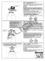
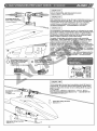
FLYBARLESS SYSTEM INITIAL SETUP STEPS
1. DIR : DIRECT MODE TO BYPASS GYRO FOR
MECHANICAL TRAVEL AND NEUTRAL POINT
SETUP
DIRE AT EAU CEE
SET button
SETS:
Connect the power
te 8h
A CAUTION —
x №
ARRE RTE AE
STEP1.1 : ENTER THE DIR SETTINGS
582 1.1 : ADIRIZÆ
Press and hold the SET button while powering up the receiver.
Release the button when LED 1-5 begin to cycle. Press power
=. =z cycle to enter DIR mode. The DIR green LED will light up
indicating the gyro has been bypassed for neutral and
<a Pi] & mechanical travel range setup.
ZZ > SETA > MAS EUX EE RIRE © ESSLED1—-S(DIR-A.REV)S (6
Fee + DISENO A FEAT Sé(GE) "ОВ ТОО, RIE A3OX
Be) Fybarlessiéif Ti26a co 1185 50 EIS, -
Note: If pressed for more than 2 seconds, 3GX will enter 3GX
throttle calibration mode. Re-power and enter DIR setting.
af - BIEEFEEE2 I3GXK EA 36X BEBE - SEE
iE A DIR ERIE -
DIR settings
met
(co
(EATT/AUX OUT] [_S.BUS/BIND |
1. When entering setup mode during power up, 3GX will initiate
startup process. Do not move the helicopter at this time,
otherwise swashplate will be tilted after start up. Should this
occurs, restart the setup mode.
2.1f 3GX was to be mounted inverted, please enter connect anti-
torque compensation section and set it as "reverse" (STATUS
LED turns red); to avoid the effect of the performance of gyro
lock.
1. EEE ENE NEAR INES» SOX ESTI > EE EA
Е), ESE EA ENANA E MEET -
2. AESOX ERE HEIZ 09 > SEN EEE HAY RIESE > UNAS Ва
HR Kal (STATUS EMS) LE EEE ©
Aileron 8/52
TRANSMITTER FUNCTION TO SERVO MAPPING 315352178 SiR 228315
STEP1.2 : SWASHPLATE FUNCTION CHECK
$81.2 : +FEIFETESS
Verify the correct swashplate movements for PIT, AIL, and ELE inputs.
ET > 24 FE) PIT ~ AIL -~ ELE 2& 15 -
DIR settings
| | Qe Or co |
> =
Elevator Frise 7
4 ED
Pitch 6
REV 2 NED
(BATT/AUXOUT) ( 5.8U8/BIND )
CAUTION
x e
In case of incorrect servo movement or no movement at all,
please check for proper connection between 3GX flybarless
connection to servos, as well as proper setup on transmitter.
SFE TDF HEF » 6519 53GX Flybarless (GA& 86 615R fx 12
RELI EERE TEES EE -
Pitch 0
KT
== = nn 9 nn un nn nn nn ош то O mp по CU e u mn ee mm mw mm mm pe mm = = о = от то Emm Ep CE Em ge EE mmf mE mmm
©
STEP1.3 : MECHANICAL SETUP
21.3: TENCIA AE
Adjust the servo neutral point and main blade pitch.
Oi PLE - EERAS (MET) ©
CAUTION
[AEE
Pay extra attention to these setup steps. Incorrect neutral
points will affect flight stability, and worse lead to loss of
control.
ZA SER SD NEE MEERE » PORRIERN
ЛЕВ) ©
is ое Adjust subtrims on transmitter
© a so servo horn is horizontally level
= — 19| НВ 55D LT 10 2K 3059225617 250S Ubtrim)
6
+12 Collective pitch
+12 HEM ERED
STEP1.4 : COLLECTIVE PITCH SETUP
DER1.4 : ENERO (ERE URIO ) E
Adjust the maximum collective pitch using the transmitter's swash
plate mixing function (pitch swash AFR). Recommended pitch range
+12 , maximum pitch range for advanced pilot shall not exceed +14 ,
RE CMURICE E + 127 SEEREENERE 14° [IR -
CAUTION
[AE
Do not adjust individual servos SHOPS through the servo
ATV/AFR Tunction, use only swashplate mixing adjustments.
Should any changes made to the endpoints or subtrims on the
transmitter in the future, the flybarless system initial setup must
be performed again.
COPMAGAEGERE » AtEMmASwash+TEEFILE (Pitch
swash AFR) 3E » 7 OSO EMATVIEE- —
HEEROMA EES » 1/AE E Fiybarless SERE -
While using 3GX FBL system, be sure to turn off the
following functions in the transmitter
FRA EHE
* Swash Ring % Linkage Compensation % Swash Mix
* Acceleration
Example : cyclic pitch of 8 :
Futaba 12ZH with three BL 700H's
AlLeron swash AFR : 53% (8°)
Elevator swash AFR : 53%
Pitch swash AFR : 37% (+12)
LETRA DE ES 230 :
Fataba 12ZH #5 62 BL 700H x3
AlLeron swash AFR : 53% (8)
Elevator swash AFR : 53% и"
| Pitch swash AFR : 37% (+12)€
+8 Cyclic pitch
+8 BREA
STEP1.5 : CYCLIC PITCH SETUP
245 1.5 : (ERA Pa TE
Swashplate cyclic pitch setting: With the main blades parallel to
helicopter body, throttle stick positioned where main pitch is
0 degrees, move aileron stick all the way to the rignt adjust the
AIL mixing ratio within radios SWASH menu so the main blade
pitch is the factory recommended value +8 degrees. The ELE
mixing ratio in SWASH menu can be set to the same value as AlL.
TEE - NE DE GE HPIERER EERE EOE
TENE BEER‘ Has wach PAILLESEE + (PIE)
BRE SFM 4/6 +85 - FEE wash EL ELLE ETE RSA LES IEBENE] +
If adjustments Is needed for aileron and elevator roll rate, it can
be done through 3GX interface's flight mode settings, or through
3G X PC interface.
Bs are al BR Fe HH ER EEE ENF © OJ(A3CXEMRE AICXRITHIM ARTE 25
SGXEKE TERE ©
| A CRUTION |
Adjustments to the CCPM servos endpoints should be done
through transmitter's swashplate mixing function (AIL swash AFR).
Do not adjust individual servos endpoints through the servo
ATV/AFR function. Should any changes made to the endpoints or
subtrims on the fransmitter in the future, the flybarless system
initial setup must be performed again.
CCPMAR NS ETIZRET + LEAL Swash+ FERTIL RHF ›
EF ZER{DRSEATVITIER - REE MINAS + LU)
2 EXTE FI ybarless 18 71€ +
2.E.LIM SWASHPLATE MIXING TYPE RECOGNITION
AND ELEVATOR ENDPOINT SETUP
E.LIM+F EERE RF ERTIEERTERL $
STEP2.1 : ENTERING E.LIM SETUP MODE
282.1 : ¡EA E.LIMESTE
While keeping swashplate level and main pitch at zero degrees,
press the SET button to register the neutral point and enter E.LIM
setup mode. The E.LIM LED will lit up after DIR turns off.
TT FÉEMSXE - DER SE OUNAE M» 15512 N SET DIR
E > E.LIM JENS EST > SE AE.LIMA MENCITIEE" E ETA °
CAUTION |
| = E
The throttle stick position where main pitch is 0 degree must
be maintained through this setup process.
BPE AER ENE SEO TE - TAE)
E.LIM settings
E.LIMESTI,
е
urs Qoov I (000)
DR ELIM EREY ALIN & REY \) =
|
„
(Ry
{| AO SCT QUI М WNL Sr
TIEN
STEP2.2 : SWASHPLATE MIXING TYPE RECOGNITION
AND ELEVATOR ENDPOINT SETUP
DRR2.2 : + FREE DTS A ЕНОТ КЕ НВ ВЫ ЛЕ
With all channels stafionary, move the transmitter elevator stick
forward, and then back to center position. This completes the
swashplate mixing type recognization process.
The control unit will determine the CCPM mixing ratio or
traditional mechanicalmixing maximum elevator endpoints.
iE Eas EL EERO EE DRE EMILE EE) - Bid EEF
PELE > EA INE °
GX Flybarless FS CCPM EE EA AE ERIN ENE O HITE -
ATEN
+ E
Throttle stick position where main pitch is 0 degree must be
maintained through this setup process.
MPSS EN INN ACOENTE › ОТВ) °
Throttle stick must be maintained
E.LIM settings
E.LIMiS=t
ЯН РЯ ЗЕ ТЕ 1) ХЕ
|
chun (Doov Neal
DE CLIM CECY À Lui A RD GLE
Ben ea:
) Gm:
| Le AL ELEV ERIE)
3. E.REV ELEVATOR REVERSE SETUP MODE
E.REVA BE E Pe 97 45 1E 52 (0) ETE €
Helicopter tilting
direction [1
Swashplate correction
direction
РОВЕР)
Helicopter tilti
direction
16% RE UA E 75 10]
Press the SET button to enter E.REV setup mode. The E.REV
LED will lit up after E.LIM turns off. This setup mode sets the
elevator gyro direction
1. Tilt the helicopter forward as shown in diagram, and check if
swashplate is tilting correctly toward the back.
2. If the swashplate is tilting at the wrong direction, move the
transmitter elevator stick until STATUS LED changes color,
and re-check the swashplate tilting direction.
EET T "SET "$8 » HiZ TET E/N"E.REV HEPES ERO" "EZ EET, >
ТОРЕ НМА, > E.REVISTERE > MET EA NEIRA E E SO -
1. Me > AS ORBE + EI ELO: SIETE ©
2. ET FEO IEEE > MERECE ESTATUSIS A » BX
leo + EE DOE 5 ERE -
E.REV settings
E.REViET,
re
4. A LIMAILERON ENDPOINTS SETUP
A.LIMEl 3% 17 12 E 82 ERI
Press the SET button to enter A.LIM setup mode. The A.LIM LED
will lit up after E.REV turns off. With all channels stationary,
move the transmitter aileron stick to the right, and then back to
center position. This completes the aileron endpoint setup
process. The control unit will determine the maximum aileron
endpoints
HEE SET RE » Ha ERTIVEA"A LIMB BTIER"SRERT, » [LIFE.REV
EVER à A.LIMISSSRE - 1987 FOO ETE > STE BERFED » TAN
ILSZAE > «HIOX Flybarless EF EN О] ЯН ©
ем
x #
The throttle stick position where main pitch is 0 degree must be
maintained through this setup process.
APE AER REA EOERUE » AIEEE «
Throttle stick must be maintained
HIER Е
A.LIM settings
A.CLIMET
"ob. =
EA I = AIL br 5 = So NE
QCD)
=
(#90) ®
Mode 1 Mode 2 Ex, % (mA
L
5. A.REV AILERON REVERSE SETUP MODE
A.REV Bll 32 fg %% 6 [ER [0 58 ХЕ Ле т
Helicopter tilting
direction
18 08 MATE 75 66]
=
direction
<—
direction
+ FREE HO
730
Helicopter tilting
ВН А
Swashplate correction
Press the SET button to enter A.REV setup mode. The A.REV LED
will lit up after A.LIM turns off. Tilt the helicopter right as shown
in diagram, and check if swashplate is tilting correctly toward the
left. If the swashplate is tilting at the wrong direction, move the
transmitter aileron stick until STATUS LED changes color, and
re-check the swashplate tilting direction. Press the SET button
again, and the control unit will restart with all LED's flashing.
This completes the flybarless portion of the setup process.
RE SER DERIVEN "A.REVEIHICIRIB ERO" SEET > ¡OS
A.LIMISIR + A REVIGRIE + [ERTINSUE SIIC IEEE O > MUERE
ESTA +» 3GX Flybarless 1643-2207 181215 + UNER) » JOSE
EIER > EA "STATUS" AOS > PISCO ®
EE + "SET" BIER AMET - PrE/LEDASPSEN) - |THE -
| 74 CEUTION |
> =
3GX Flybarless system must remain
stationary during startup. Do not move the
helicopter until the swashplate jumps up and
down slightly 3 times, indicating the
completion of initialization.
3GX Flybarless 1505 SE AO ICARE » GOT
ESES * CUOICTAE > + FE SRA
ME CREEN + ZT -
A.REV settings
A.REVET
3GX THROTTLE CALIBRATION 3GX&zaslPITIZRIE
A CAUTIEN
x E
While setting throttle
calibration, reset throttle
curve and pitch curve to
default 0-50-100.
EIRP TAEIEDS » SENSIEN
REE ERAS E7Ea2 0 50 10028
RE QG
100%
Throttle/Pitch curve
HPS/GREE FAR
Press 3GX SET
button
FZ 3GX SETHI
в
50% ensure kenn ren
0%
Release SET button
DFSSETSE
Orme Oem Mes
DY 000 Na»
[ 48U6/6mD |
EE
(mT ou)
Move the throttle
stick from lowest
to highest point
ios HP IERIE REED
JE ESB NE
Turn on the receiver
power
En
BATT E ESC
—
Hs
LED on 3GX panel all
light up
of SGA ER | LED FE
BEER
| STATUS GOV De [peo] В |
e: me Goo © =
E
SET “я
i
Ta
| a, hn eb fey [THR] |
After finish the setup, red
and green LED start Take off the
flashing and 3GX restarts recelver power
GR AEG > MUERE PI > BA PIE IER EIR
IX ENS
| Efe]
STATUS Goy i
Dem ere Nei BATT ESC
= y A, NED =>
se y
| << a Ev | | |
FLIGHT MODE SETTING 17451527
Operation Instrution
1. With 3GX in operation mode, push rudder to left or right, and press the SET button for about a second.
2. After entering setting mode, the STATUS LED will flash specific number of times to indicate specific settings.
J. During setting process, LED1 to 5 indicate the rate of setting; flashing LED represents 10%, while steady lit LED represents 20%.
For example, if LED1 and LED2 are steady lit with LED3 flashing, the set rate is 2*20+10=50%.
RIFF
1. CE DEREN NN‘ KERSETR— A >
2. JE ARTE ESTATUSOE SES DEJE EZ PTE A ANETTE ©
3. TER ERIE OLED ~5 FFE - LEDS AE10% : LEDIE {420% + MINLEDI-LED225 - LED3PS4% » DE (AA2"20+10=50% -
The LED flashing frequency indicates setting position.
Single flash: Fli
Double flash: Elevator end point setting
Flash in group of 3: Aileron end point setting
Flash in group of 4
rate adjustment
Ns EE ONO ESTI
| Move rudder stick
RB EAC ET
PTA a ae
SE rR Ane
SE RI Fag ed Tn
Nl EERE a =
ale Bd CHR EE i
Ps
} à, = |
Gus (вом
Vas
”
QUT] | S.BUS) BIND
Y
BATT | AUX
| : Swashplate dampening setting
Flash in group of 5: Swashplate accelerate setting
Fully
Fully lit LED1 indicates 20%
lit LED2 indicates 20%
Flashing LED3 indicates 10%
So the setting value is 2*20+10=50%
MESE va
MPAA A
LED 10%
ONES TE (E 732720+10=50% -
1. AILERON ROLL RATE E#iRZEFE
Setting Instruction:
1.After entering setting mode, STATUS LED flashes once.
2.Ailleron and elevator rate can be adjusted independently.
3.Moving the aileron stick will display aileron roll rate on the LED. The more LEDs, the faster the roll rate. Moving the aileron stick
can increase or decrease the number of LEDs that lights up between LED1 to LEDS, which sets the aileron roll rate. Same method
is used to adjust the elevator flip rate when elevator stick is moved.
4.Elevator flip rate is a geri based on aileron roll rate. When the difference between elevator flip rate and aileron roll rate differs by
20% or more, 3GX will automatically adjust until the error rate falls within range. Therefore, we recommend adjustment aileron roll
rate first, and then adjust elevator flip rate.
5.Moving the related control stick, LED will automatically jump to the set rate display of the specific stick function. For example,
moving the aileron stick, LED1 to LEDS will display aileron set rate. Moving elevator stick, LED to LEDS will display elevator set rate.
BRIER :
1.3 ASE STATUSHIIS SPIE —
2.5 BEA E REEF LIS FRE
3.3 EE EME EEE LEDS - EE SARTRE - REE REO ENS AD LEDI-LEDS TIENE + ¡EMM MENE RENE [6]
RO FAENA REE E 2LEDISE ODA A ERE ©
4. AD EEES METER ELE E20% LL) E > 36X8 O ER AE REE - PEA EEE »
5. 8NiBENIEISLEDE BEM EI IRRTE © PIERRE - LED1~5TE aH TEE - ALEJE » LED1~-5E TRAEN E -
‘Move aileron stick to adjust aileron roll rate STATUS Single flash
Move elevator stick to adjust elevator flip rate | STATUS Single flash
#3 5) 2 99 1219 EH BR RE нЕ a BUT ETRE REE iliac BA
A i
> mg fe LL Qu Om X]
bn а -| | a AIL С : — À mm жен Slant
\ [Mode О Моде 2 a;
2. ELEVATOR END POINT SETTING HET EM RSÆ
Setting Instruction:
1.Before entering elevator and aileron limit setting, please switch the transmitter to throttle hold mode and push the throttle
down to 0° position to avoid mechanical interference due to excess travel range.
2.After entering setting mode, STATUS LED flashes twice
3.After entering setting mode, elevator may deviate as much as 8 degrees plus compensating rate either forward or back.
Moving elevator stick can adjust servo travel limit. For example, if LED shows 50%, total elevator travel range is 8+0.5%8 =
12 degrees.
4.Generally 70% is suitable for most helicopter frame. If recommended value is not used, please adjust setting until
maximum is reached without mechanical binding.
aTEB
1. EAH IEEE BI ET TIE PR ER El, sa Toit es WRT BAUR TN, IR BPS EIR sR TE 0B 001i Bi Bt Se TIE BAIT ERS Ia Ti
2.3ENER EESTATUS OEP ©
ENE THEN ES MESE+9NELE - SOREMAINAE - EFE EDLER - MILLEDERTEIZE230% + HIEMTIERITIERS+0.5*8=12E -
4.— RM =70% IT ELLESFITSA BL OEA TEENS - MENSAEZIE Mar RICE FA, MIRE -
tor stick to adjust elevator travel limit| [578 (TTT ie
Ре БВ @ ЭТАТЧУЗР 2
oO Ne;
3. AILERON END POINT SETTING в! {7 В НБ 28 ЛЕ
Setting Instruction:
1.After entering setting mode, STATUS LED flashes 3 times.
2.After entering setting mode, aileron may deviate as much as 8 degrees plus compensating rate either forward or back. Moving
aileron stick can adjust servo travel limit. For example, if LED shows 50%, total elevator travel range is 8+0.5*8 = 12 degrees.
3.Generally 70% is suitable for most helicopter frame. If recommended value is not used, please adjust setting until maximum is
reached without mechanical binding.
SRIE SEA +
1.:3E 50 E (ESTATUS AIZ SER — 7 - ; _
2 EANREINERESEHIMRE - AYERIRG > Sale TRETEN - PIAILEDERTEE 50% © КОНЕ 281239 +0.5*8=12 8 о
3.— EM =S70% 5] РНК) а Ss Ras - IEEE ABE Нав E 2 AMS PEF MIRE -
aa
aa
— = — A === een" === UN A ga == a |. | =
e 5 ОД PO E a ес се at group of 3
Н 4 = : 15% El all SE TE 17 90 16 ea 1J 15 10 ВК В ES al. Ee
1 m
= = Е С X > =
= ar LI = — - É
== E Ци В —— di ER: al [| he. dica (Свен EN 5
NT - - i UL} oat i A ao el ® alé
у TF “| | J i é | LT | hy Ta r
-=-)| |- = AIL [F273 Uf == 208s —— M) Mice EE
— orden) (ad, rd, O EE
(UD) =
—|Mode | | | [Mode 2 mt e (НЕ)Е
10
4, SWASHPLATE DAMPENING SETTING +8 E/1L587E
setting Instruction :
1. After entering setting mode, STATUS LED flashes 4 times.
2. Move the aileron stick to adjust cyclic pitch dampening rate; the more LED lights up, the more dampening effect. Please note
aileron and elevator dampening cannot be adjusted separately. Moving aileron stick is for adjusting cyclic pitch dampening
rate, but moving elevator stick is for adjusting collective pitch dampening rate, NOT elevator dampening rate.
3. The more dampening effect, the smoother helicopter flies, but feels less direct. The rate of dampening should be adjusted to
suit pilot's preferences.
aX Ean tH
1. ¡EN ER EESTATUS ASE PIE ©
2. ETE OU AER II LC - LEDSISES ES - (BEBER HERA DOE AE METE E AE RIAL E - 16
TENIENTE SSL - MIENEMREERZ - |
3. HIUEEÉES HIERTHTR © BAER - CEE LUBA NOFReidE ©
Move aileron stick to adjust cyclic Move elevator stick to adjust
pitch dampening STATUS Flash in collective PAC dampening STATUS Ejash in
SEE MES TEA hl BEF EER ERRE EEE SEE men
== JA fi A =) uc ER [ + Ca
A y La - Ц | | Gus (Door deco р, ) | || e RP || | a Gs (вом decos
e TI ¡E má 88005 VIE 4 rie re Е 88000, VEL
UN = Bu cil Usd ELE ET 21200 Nao:
ada adn das” mda o Tinka Ai a | 5
[Mode 1 [Mode 2| [Mode 1] [Mode 2] | | <-* NS |
5. SWASHPLATE ACCELERATE SETTING --=2 038 82 ХЕ
Setting Instruction:
1. After entering setting mode, STATUS LED flashes 5 times.
2. Move the aileron stick to adjust cyclic pitch acceleration rate; the more LED lights up, the more acceleration effect. Please note
aileron and elevator acceleration cannot be adjusted separately. Moving aileron stick is for adjusting cyclic pitch acceleration
rate, but moving elevator stick is for adjusting collective pitch acceleration rate, NOT elevator acceleration rate.
3. When cyclic pitch acceleration is active, hovering point fixation ability may be reduced. Beginners or F3C pilots should
minimize cyclic pitch acceleration rate value, or set it to zero.
a ESTO :
1. EAGRERSTATUSHYIS IERIE RN -
2. iE BRIER E MRE ERES © SESS @ IES © BF IEaIREAIFIEE NI SRGEE - LUSTRE REF ERRE DE > DIE
ABENCIEN E e IRE EEE MIEARERIEEE -
3. FERIISIR TIE NOTE > SISPAE ENTE TEE - MESE 3CAIT Scan e RIE DIRE ЕЕ E, + ENERTE m0 -
A | Setting swashplate acceleration may increase the burst amp draw of servos. Therefore, BEC output capability should
— be confirmed fo handle burst current when setting collective pitch acceleration, otherwise insufficient current supply
may result in flight accidents. We recommend direct power supply if acceleration is higher than 50%.
EE ARES ERE ES PT AE ERE ER IRIENDAE + MA EEBECES iee sE Em + SRIBIEESEM
(REE RNE + MSIE - AEREA E- EA OESTE E50%LL CONERTE (E -
Move aileron stick to adjust cyclic ; Move elevator stick to adjust
pitch acceleration STATUS Flash in collective pitch acceleration
STATUS Flash in
E ze #% E96 0; groupof5 #2 95 11 groupofs
15% EN El 1€ 19 58 2x RB E TN DD RE COPE: SNC SE 087 TE TO e ETS,
(659)
8 O eof
4 NN ESE
AC) =
VG 1 ® o mE
RUDDER GYRO SETUP Effie
After the system reboots, part of flybarless setup is completed. Now the rudder gyro needs to setup. Push and hold the SET
button for 2 seconds to enter the rudder gyro setup mode.
If your transmitter has the following settings, please disable it or set the value to zero.
TINA AFI ybarles SIONETEN » EEN TENIA » ¡SINE TI519" ETRE? ENCICMBRE -
NR TN ELBE THIER - MILE MINENOFAMEN TAL -
@ ATS @® Rudder to gyro mixing
@ Pilot authority mixing @ Pitch to rudder mixing
@ Throttle to rudder mixing @ Revolution mixing
AUTO | 3GX Flybarless rudder gyro has the factory setting of 1520 u s and DS digital servo. Double check your servo spec
and change the gyro setting as needed to avoid damages to the servo.
3GX Flybarless ERIN MRE AA : 1520 1 AERDSMUNORSES TIENEN ZO ERES ESPEREN RENE -
1.1520 4 S (STANDARD) OR 760 y S(NARROW BAND) SERVO FRAME RATE SETUP. 1620 y s(i52$)27760 y s(7EZA CIR але
3GX Flybarless system is compatible with both the 760 1 s narrow frame rate servos (such as Futaba $9256, 59251, BLS251), as well
as the standard 1520 uy s frame rate servos (most others). Proper frame rate must be selected based on your servo's specifications.
To enter the setup mode : Press and hold the SET button for 2 seconds until STATUS LED flashes. The 1520/760 LED will
lightup indicating servo frame rate setup mode. Push the transmitter rudder stick left or right to select the frame rate. For
example, if rudder is pushed to the left (or right) and STATUS LED turns green, the frame rate is set to 1520 us. Tosetitto
760 us, the rudder stick need to be pushed from the center to the opposing end 3 times for the STATUS LED to turn red,
indicating frame rate set to 760 us.
3GX Flybarless panel : Each setting value is labeled on the 3GX flybarless control unit with either green or red lettering,
which corresponds to the STATUS LED color. Subsequent setup mode is entered by a single press of the SET button.
Setup mode will exit if no activity is detected in 10 seconds.
11
3GX Flybarless15 ME RRE AR » STEAMER EEISTE0 y AM ( Futaba 59256 « $9251 - BLS251) » RIL)E¥3GX Flybarlessig Ele
76088 + ELAIE 7760 SIRISOVOIRSE » — ARES 21520 | STAM * AE 231520008, -
BERN : SEER C6" SET DERE) > ILS" STATUS" {EEE TS SEHE » B"1520/760"MINAIEIETESHE » READE /
EROBERN NSS HERE SORGEN EL (NE) "STATUS ENERRE > EminElA1620 us
SEEN EIA760 us AMOS © BSED BEER HEBER F STATUS IE NEBRIIE » FBHEAT60 u AMI -
3GX Fly Баг! ИК "STATUS" SP Е: 618" SET"82—001E A F—BZE › 50210) A
TIO OD AER Ax MSI FRStET" EPI ENE + EE TOA RE — NOE BIS + SZ NOT
=
NA
Green LED , 1520 i s standard band
Red LED : 760 2 s narrow band
AUT LENTES
ES es
ax
Select by moving the rudder stick left and right
A 65075 OE
Standard/Narrow band mode
Ki E MET,
2.DS (DIGITAL) / AS (ANALOG) SERVO SELECTION DS /ASXBLC (AR 253€
There is a direct correlation between servos' speed to gyro's performance. Faster servos are able to execute commands from
the gyro at faster and higher precision. Due to the high performance gyro sensors used in the 3GX flybarless system, premium
high speed digital rudder servos are mandatory for optimal tail performance. Some of the recommended rudder servos.
Setup method : Press and hold the SET button for 2 seconds to enter the setup mode, then press the SET button to select
DS/AS setup mode, as indicated by the lighting of DS/AS LED. Using the transmitter's rudder stick, select either digital servo
DS mode (STATUS LED is green),or analog servo AS mode (STATUS LED is red).
{ol AR S38) {FREER PER FEB IEEE » (5) НВ зе В) ГЕНЫ » FLEELIENR BIER EELRET » BF BIREIFEBNEE : HIRSEX Flybarless 25185 4:5005 76
HERE EE - PTA ITS CER EBIUGMRS » 115 EME »
SENT: 1510" SET" SERRE DERE EI, > BT SETREZIEDS / ASK (DS ASIETISE ): ABO ERUDS (STATUS SG)
MNÁRECAS ( STATUS И 15) (lr 35 *
Green LED : DS digital servo CAUTION Using an analog servo in DS mode will
Red LED : AS analog servo cause damages to the servo.
MS 0m rE DS zn A SEE FE SR Se ча же (Е ро ЭВ Е 6,
O EE DS PIBE" ASÍA LEONA 2511535 2410) AR 251 8
i è Co az by moving the rudder stick left and right
Gras Que des = 5688)5 600 ZE
Фо Vie: ; ;
фа e — >
"=" a
Digital / analog mode ese veal RUD \ |
TILA [Mode 1|
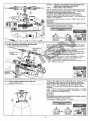
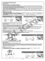
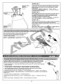
3. RUDDER SERVO DIRECTION CHECK AND LINK ADJUSTMENT RE EAft {EARS EEE DE
Move the transmitter rudder stick left/right, and check for the correct direction of the rudder servo. If needed, servo
reverse is done from the transmitter's REV (reverse) function.
For tail pitch adjustment, center the rudder servo by either setting the 3GX flybarless to normal rate mode (non-heading
lock), or press and hold the SET button for 2 seconds. With the rudder servo centered and servo horn at 90 degrees,
adjust the linkage length until tail pitch slider is centered on the tail output shaft as shown in diagram.
TSE ERERLQIRBBAN SOE SEE - SA EESENERSE COEN OIR 351328770 -
133GX Flybarlesst]ipy IF IRER IV FT SETE2) › 1D FEACIOÍN Str PIBE > DORA > AEREA OIRES 90€ » El
9 НВ ВЕР Ис РИВНЕ СВ ©
Approx. 10mm
110mm
— |]
=
5 ENE
> 0° | Os. ©
©
Tail servo hom
ECHES
Tall case set
EEE
4.GYRO NOR/REV SETTING NOR, /REVPCIZEE IER QFE
Lift up the helicopter by hand, and turn it to the left (yaw). Check if the rudder servo is applying correct compensation to the
right. If reversed, set the NOR/REV setting as follow.
Setup method : Press and hold the SET button for 2 seconds to enter the setup mode, then press the SET button to select
NOR/REV setup mode, as indicated by the lighting of NOR/REV LED. Using the tfransmitter's rudder stick, select either NOR
(STATUS LED is green),or REV (STATUS LED is red).
RCA A ERES) - SENOR 50 OE 3007 НЕЕ GRE OR - Rn IRENEIEL ORE SNEERBE ER ORE -
SEHR DN : 17SET"RE20NEE A DERIO ENEE > JEMENOR /REVIZIA + 175 OEA ENOR( STATUS 3456 ) REV ( STATUS/AADE ) -
12
Green LED : normal direction = : = |
Red LED : reverse direction Select by moving the rudder stick left and right
TOREO EE
E
E A AE
M STATUS (sow
ER E LIA CE ALIN REY
Gyroscope direction settings
Pe 47 € LE a
5.LIMITRUDDER SERVO ENDPOINT SETTING LIMITE #6 5) IR 21762 € a 2
Press and hold the SET button for 2 seconds to enter the setup mode, then press the SET button repeatedly to select LIMIT setup
mode, as indicated by the lighting of LIMIT LED. Push the transmitter rudder stick left until tail pitch slider reaches the end, then
center the rudder stick and wait 2 seconds for the STATUS LED to flash red. Then push the rudder stick right until tail pitch slider
reaches the end, then center the rudder stick and wait 2 seconds for the STATUS LED to flash red. This completes the left and right
endpoint limit adjustment of servo travel. Insufficient servo travel will degrade helicopter performance, while excessive travel will
cause binding and damage rudder servo.
FH SET" SEE AD BEN ART « SERRE RITEDP IIE LL » EELIMITEIS - FEE ORESTES (FREE EDZRIAITE
RE + {SEIDEL 420/6"STATUS"ENCERÍDENS ATTUCREDRE : EEES UE PINES AMTIZREE - BisigE
DIFFPIIESTE) - 527048 "STATUS" IE ERANEPYE - BITE I GTIERRE (TEBTNEREFENREREER RENEE » TEEISA Ss MORE =
Mode 1]
Mode 2) ак
Push the transmitter rudder stick left until tail pitch slider reaches Push the rudder stick right until tail pitch slider reaches
the end,then center the rudder stick and wait 2 seconds for the the end, then center the rudder stick and wait 2 seconds
STATUS LED to flash red. This completes the rudder endpoint limit for the STATUS LED to flash red. This completes the
adjustment for the left side. rudder endpoint limit adjustment for the right side.
9 SPESEN ACERA TER E 1 - ¡SEDE PICA 19 ESSE EN - PEA NONE ATERE E - mie
TEN FIER STATUS IERIE RRA TIZEsCIEE TTA * Der PIE) HE STATUS ES NOTE LIEB ©
Flashing red LED indicates AE
settings have been registered à 5
NECESA ED Rudder travel limit setting lower than 50% will not be registered.
Mechanical fix (moving link ball closer to center of servo horn)
is needed for excessive servo travel when LIMIT function is
below 50%.
EC TI IE 8 2 EM 011A7550% » SR/3GXA Flybarlessi$ 4 Pac’ GE
17 ЛЕВ НОЕ > SEMI E SER XT - AT FE CRE RES OPE
8] › BETTER E RECIENTE -
Endpoint limit settings
EME
6. HELICOPTER SIZE AND DELAY SETTINGS E HDELAY IZ fll SEE 8 55%
This setting includes two functions :
(1) For small helicopters such as T-REX 250/450, set this setting to small helicopter (STATUS LED red).
For larger helicopters such as T-REX 500/550/600/700/800 set this setting to large helicopter (STATUS LED green).
Ith 5% TE #5 = FM IS IN EE
(1) 3GX Fiybarless EE / ENDE : SARENET CANET YD : T-REX250/45065 2121 / ARR AT, (RES
"STATUS" EEE) ; T-REX500/550/600/700/800:5 Seh UA (SE "STATUS" НЗ ОВ ев ) »
Green LED: suitable for larger helicopters such as T-REX500/550/600/700/800
Red LED: suitable for smaller helicopter such as T-REX 250/450
a == EEN EA
EC Le EEE а .
suo x Select by moving the rudder stick left and right
Vico ZEHHDZAREE
Y
Helicopter size selection
and servo delay settings
EN N I fi
(2) The DELAY function is utilized when slower rudder servo causes tail hunting (wagging). This can be observed after a
hovering pirouette comes to a stop. If tail hunting occurs, gradually increase DELAY value to eliminate it. For best
performance, DELAY value should be kept as low as possible without tail hunting.
Setup method : Press and hold the SET button for 2 seconds to enter the setup mode, then press the SET button to select DELAY
setup mode, as indicated by the lighting of DELAY LED. The choice of small or large helicopter is done by moving
the transmitter rudder stick left or right while observing the color of the STATUS LED. For small helicopters
STATUS LED will be red, and large helicopter will be green. The amount of servo delay is set by how far you push
the rudder stick, followed by pushing the SET button.
13
RRA Bo mee ERAN ED Es CARTONES CNE BORA
SET : 15H12" SET" SE2 RME ADRESSE TN + 1448 DELAY STE + DOS SÉCISIFEIE LATTES + UN: T-REX 250/450 ( STATUS RAS) - PAT
BH F540 T-REX500/550/600/700/800 (STATUS AS) › ЖЗ DELAY mel - RIFIRD OES) RRRE + EIFHPLIIE
ua OA ” MEE ATEN EA 100% + HEEE PEONES EN » de p SET SIA > ENOJO E EA
т 3 °
Gradually move the transmitter rudder stick until DELAY
Green LED for T-REX800 LED begins to flash, the delay value is 0% at this point.
LESS E PET ONCE DELAY EPG » IEEER0%
0% when DELAY LED
begins flashing Continue to move the rudder stick until desired delay value is
DAWN bebe er kA needed, then press the SET button to register the setting.
Maximum is 100% delay, with rudder stick pushed to the end.
Green LED for T-REX800 = ETE: 100% » VS 1218 ,Ç
NN pee ABE SR TIE iF HEE PATRAVIES » #2 PF
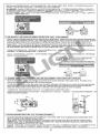
7.ANTI TORQUE COMPENSATION DIRECTION SETTING REED
To achieve consistent gyro gain on left and right, 3GX has built in anti-torque compensation function. User need to confirmif
3GX Is mounted right side up or upside down.
Right side up: Installed with 3GX label facing up, anti-torque compensation set to positive (green STATUS LED).
Upside down: Installed with 3GX label facing down, anti-torque compensation set to negative(red STATUS LED).
TERESA E — El IX RIE ARDE, EESTRERNIOSS PES °
IEE | ZTRIGIGXEHREE LL + 20776 AEN(STATUSIIE) ©
iz © ZRIGIGXERE | RAA ES ARE (STATUSÉI IE) °
Setup method: Press and hold the SET button for 2 seconds to enter setup mode, select until anti-torque compensation section, as
indicated by lighting of all 5 setup mode LEDs. Using the rudder stick to select either positive anti-torque compensation (green
STATUS LED) for right side up mounting, or negative anti-torque compensation (red STATUS LED)for upside down installation.
ENT : 1512" SET" RE20NE A DEE ER > EEE AA ER EJEA SAMEN EEE’ KELLER ESOXILEN * ARTFR
IEE(STATUSHIE) | B3CGXREN - HIT AR OSTATUSADE) -
Green : Right side up mounting
Red : Upside down mounting
poe Le) SIE al Ma :
Ne E CS Select by moving the rudder stick left and right
TSE aa
Anti Torque Compensation
direction setting
Ea MR
8.SENSITIVITY ADJUSTMENT %£ 9%
For radio with built in gyro gain settings, gain can be adjusted directly. For example, 50%-100% setting on the radio translates to 0% -
100% gain in the heading lock mode; 50%-0% setting on the radio translates to 0%-100% gain in the normal (non-heading) lock mode.
Actual gain value differs amongst servos and helicopters. The goal is to find the maximum gain without tail hunting. This can only
be done through actual flight tests.
The recommended starting point for transmitter's gyro gain setting should be 70-80% for hovering, 60~70% for idle-up. Value should
be tuned under actual flight conditions by increasing to the maximum gain without tail hunting.
— MRE AIERIE BE SEVRES à » JERE ACYROLNGERIE ETRE BRIERE + SREIBES0% 8IFEIRIBHIRER0 » FZEIES0%~100% > ENFRIA REE
EEA REEN0~100% : 2 F(E50%-0% + RUPERT (E 73 7FÍS EA REGIO -100% =
ASENSI RE EN NOME ems TÉ SERE (EFREMERICIEENE ) BATE HEEE RS » PERE
i258 8 PRT THUA ARE THEE -
&E AER BRE RENEE > MIES SAA Ta ETE 10~80% 776 > Idile upfRITHFEREIE60~T0% LE « ZEBIKEIFRRITEOAAREBITIZELE » UE Et
HERE - SEEM ERE BIEERE -
AEE For radios (IE Futaba) using 0-100% as heading lock gain scales, the recommended gain setting is 30% to 35%.
: For radio that uses the 50 -100% scale(such as JR and Hitec), the recommended gain setting is 70% to 75%.
HERE B/R0~100%01:&Z 28 : Futaba » 07 FE (530-3510 : RER EE 750100411612 28 › ПОВ - HITEC - ESRF BET T0~TS%IT -
Specifications EE Go IRS
1.Operating voltage range : 6.0perating temperature : -20°C~65°C 185RZ# : DC 3,5V—8.4V 615 BRIE : -20C—65C
DC 3.5V—8.4V 7.0perating humidity : 0% —95% 2:HE EM : <80MA @ 4.8V 7 1586 : 0%-—-95%,
2.0perating current consumption : 8.Dimension/Weight : 3.0 RAAAEE : +300%sec 8.R TEE:
3 phi po tla vate 1 2200" 066 Bice icra sings 4.5 AS : + 600 /sec 36.5x25.2x15.6mm/11g
; HE oHS certification stamp . 12bi = ет
4. Rudder yaw detection rate : +600°/sec S-RAMESsRFANS + 12bit(1211T) OFF SRoHSIRIRE
5.Sensor resolution : 12bit
14
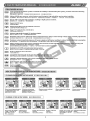
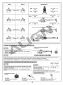
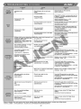
4. 3GX SETUP TABLE SEX
ALIGN
7
e Settings 3GX throttle calibration Rudder Settings Flight Mode Setting
TFRETE IGXHPS {TIE IE FE NP ESTE MATE ES TE
Turn on transmitter, Turn on TX, lower throttle all | With 3GX powered up, press | With 3GX powered up, push the rudder stick
press/hold SET, power on |the way down, press/hold SET for about one second. left or right, and hold the SET button for
Enter Setup | heli release SET before SET, power on heli, release {FICK FIRMED БЕТ #1) — about one second.
ss LEDs stop scrolling. SET after LEDs stop scrolling] # » EIOXEENTEPI ENEE BE
PRA METAS ' SETE > ale SoHE ES + ei PIENSE SETH ©
1 DASS IO AIRE (ES + E a ' el
oie TE 00 ,
LED 1356 | LED1 lit LED1 = LED1=5 all lit up LED1-5=5|LED1 lit LED1 = | STATUS flashs green 1 once STATUSFÉS{518—T-
Setting [Mechanical Travel and 3GX throttle calibration Wide/narrow servo band setting | Cyclic pitch speed adjustment.
EF |Neutral point setting IKE YT NTE F/7ESA NAS TE EERIE REE
Ht TIES PTT Rhee iF |
Setup swashplate Push throttle open fully to | Set servo wide/narrow band Move aileron stick to increase/decrease the
Setting movement on TX, and set |complete Ce indicated |using rudder stick. Green LED | number of LEDs lit between LED1~LEDS5.
1 the right aileron cyclic pitch| by flashing of LED1~5, and | for standard wide band servos. | More LEDs means faster rolls. Same
to 8 nt on cyclic then enter normal For narrow band servo, LED methods applies to elevator using elevator
rs mixing ratio in a operation condition. will be orange until rudder stick to control flip rate. Aileron and
BS E — Setup |menu can be set to the FBP 2e, 10. |Stick is pushed 3 times to elevator roll rate need to remain close, with
1>Li confirm setting and status setting deviation to remain within 20 %.
Method |same value as AIL. _ |LED1~LEDSE3# + #¥AFRE | ED will turn fo red.
BEST | EE + FAME 358 O ВНЕ us 4>LED1-LEDS=18
iso 58/5 « HFM BEER 9/72 SA EREHE e AGE A 1 on LA
swash [FZ BE LF REET] - STATUS{#/25 — ARRET * EE : ВЕН!
BET NA © AR EP RR ı STATUS EC a °
Tele > E M1 EAT -
LED 1556 | LED? Lit LED? 5% LED? lit LED? 55 STATUS flashes green 2 twice STATUS PS N
Setting |Elevator Travel Limit Setting Digital/Analog Servo Selection | Elevator travel limit setting
ER |AERTERE ei EL ERR мере FEM TIZERRE
Push elevator stick Move rudder stick to select | While in this mode, elevator may deviate
Setting] set forward to limit, and digital/analog servo. Green forward/backward by as much as 8 degrees +
2 Me d release. STATUS indicates digital offset percentage. For example, LED
= et OC | Seas ARA ETA ZE ARA servo, red indicates analog. displays 50% settings, total elevator travel
zn — | EDT [7H ARE © + е=осежи EEE: | Will be 8+0.5*8=12 degrees. Set to a value
ANTE — FER RTE EU SA LUS ARE : ; 9 a
STATUS+15 2 8747/8955 - $86 | with no mechanical binding at extreme end
ЖА НБ © or keep default value at 70%.
EA ETHIE EEE IMR EEE CN
LEDS EE 0% MOTO J 0125 + Ey
A RAEE RES TER 70% ©
LED 1558 | LED3 Lit LED3 = LEDS lit LED3 = STATUS flashes green 3 twice STATUS 188 =
Setting |Elevator gyro setting Rudder Gyro NOR/REV Setting | Aileron travel limit setting
EM | HEMER VESTE RESTE AIT AER IE
Tilt heli forward and back Yaw the heli left/right while While in this mode,aileron may deviate
while observing gyro observing gyro correction left/right by as much as 8 degrees + offset
Settin correction direction. If direction. If reversed, move percentage. For example, LED displays 50%
5 я reversed, move elevator rudder stick to change settings, total aileron travel will be 8+0.5*8=12
Setup stick until STATUS LED direction. degrees. Set to a value with no mechanical
..—— | Method |changes color to reverse THERES ЕВЕ Л: | binding at extreme end or keep default valueat
в ДЕ = ETE т gyro direction. SZ ' EEE ' BI 70%.
i SEER y ARE ESE NEI ОСНО, fl
a E Ue: LED AT A RS0% + BAPE R8#0.5' 812% > MIE
smmUeLED El ada SA a IN 9
LED 8% |LED4 Lit LED4 55 LED4 lit LED4 STATUS flashs green 4 once STATUSP3i51500
| Setting |Aileron Travel Limit Setting Rudder Servo Travel Swashplate Dampening Setting
Setting] EF | ESTER RRR ETRE | += MEE
4 Push aileron stick to Move rudder stick to left/right | Move elevator stick to adjust collective
extreme right, and release. until rudder at extreme en pitch dampening level. Move aileron stick
SEM | Setup ВОНИ НИЕ ' RE point, wait until STATUS to adjust cyclic pitch dampening. More
Method = Cons AU Lhe e LED' sindicates more dampening.
RES sees | BRAEREINRE EERE CES - EIA
so fr FOLIFAZERBERCER © RISES « TILE -
LED 155% |LED 5 Lit LEDS > LED 5 lit LED 55 [STATUS flashs green 5 once 5ТАТИ$р9 85 К
Setting |Aileron gyro setting Heli Size and Delay Value | Swashplate > bump (acceleration) Setting
E | EEN: AIR OE E ERE BEER | + ENEE
Tilt heli left and right while Move rudder stick to change Move elevator stick to adjust collective
Setting observing gyro correction STATUS color, green STA pitch acceleration level. Move aileron stick
5 direction. If reversed, for large heli more, red STATUS | to adjust cyclic pitch acceleration level.
move aileron stick until for small Heli mode. Moving More LED's indicates more acceleration.
3A | Setup [STATUS LED changes color rudder stick to any one side to | If acceleration level exceeds 50%), check
Method |to reverse avro direction set delay. The amount of delay | the BEC to ensure it can supply enough
BELT Tort Eh VOS DONS EE is determined by distance from | current to servos. Dedicated receiver
: Ш dr center and keeps the position. battery | is recommended for acceleration
PE maT Tara Press EXIT to set. gher than 50%.
o ° LENTE ESTATUS IET + gle a
Fan BAR + STIR) EH shingrisuppanns cu. Rida
EA ECHES e Ss nu SEF 0% › № BECÆZ 57€]
TIE - SMS EIN Evan BO alk sh E: TE BE
¡BES ° ET ECN NI
| LED IE LED 1~5 all lit up LED1~5& 7
Setting] Setting Gyro install reverse setting
6 ZF MER ZT EE IE Ez [OJEN TE |
Mano Use rudder stick to set o install |
EN | Setup position. Green STATUS is normal,
Method red STATUS is install upside down.
BENT DECIR ESTATUSISNE « #218
PERLES © RZ ADS AE © |
After completing setting of 1.Flashing LED indicates 10%; fully lit LED
8 degrees SWASH, do not indicates 20%. For example, LED1 and LED2
make further adjustments. are fully lit, while LED3 is flashing, this is
If adjustment to helicopters translated to 2*20+10=50%.
. roll rate is needed, the LEDFPS {#23 10% » Z5520% - Hlt)LED1-LED2#= »
ét adjustment must be made LED3PSRE » TEA 2 20+10=50% < nn
= in the roll rate under flight 2.Move the stick to display the stick
mode's cyclic pitch section. function's setting value. For example,
0 EE E/ZONSWASHIE AE moving aileron stick will result in LED1-LED5
sas EEE Несе displaying aileron’'s setting value.
+ IBF RRS RR A ENBRBEF LEDS SEA EEE + 190 ENEN E
Rae e Tí |
15
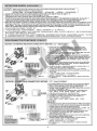
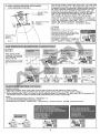
5. 3GX FLYBARLESS PREFLIGHT CHECK #®RiTaiflEEs
ALIGN
7
ee ан —Ú][——]
+ | Feo) ( | y —
——]>—] TE — —— ан =
down 3 times horizontally — E
+F ANIMEN 7” ак as
ЛА |
E
НТ | "
—] —
a _ — =
= < 6
| — —
O
©
оо ||°
OIL
O © : D (GE
STEP1 #81 |
Turn on Transmitter, and then receiver power.
RHE EESER BHREENSEIER -
STEP2#M2 |
3GX Flybarless system will go through initialization process, as
indicated by flashing of all LED's. Do not move the helicopter
or transmitter sticks until initialization process completes.
tH153GX Flybarlessif#|2515 718 STATUS RDIR —A.REVS F3} »
HOSE * DIAIPEAE SE SSÉ AIS (LE FF ©
STEP35ES
The completion of initialization process is indicated by the rapid
up and down motion of swashplate 3 times while remaining level.
Should the swashplate jumps up and down at a tilted position,
the flybarless system initial setup need to be performed again.
(Refer to page 6 Flybarless system initial setup)
The pitch of helicopter will remain locked until successful
initialization. If the initialization process is unable to complete,
with STATUS LED blinking red, Recheck all connections, and
perform another reboot with helicopter remain stationary.
Following successful initialization process, green STATUS LED
indicates rudder is in heading lock mode, while red LED indicates
normal non-heading mode. (Refer to page 14 Gain Adjustment)
MEET » Mises +SREREKEE RIESE = - EEN
EF Us ADE - AIZEma Е бе ая + HEN EPR E
Mex IE 1 (SSP.6 HF APE )
TEMER E A PUR IRAN OE RAS) FE NÉE MATAFHEZAFSTATUS
ALISPIRE - RS PTE be Sar LEN Rizo * Meco ENTE ©
EMB * STATUSTERIE ZEN ERIN + EMS 3 IFE RT *
(MS 12 P.148: 0)
Green = rudder in heading lock mode
Swashplate jumps up and
down 3 times horizontally
represents successful
initialization.
+F ENDE RAIL SEA
NB
SE A
RU
2
E
LH 1
| |
Ч y
E HL
Swashplate jumps up and
down 3 times tilted
represents setup error.
+ FRENAN == NN ACER TE
a 5%
Red = rudder in normal mode
MISA FS ACER TED
¡IE CE) AER be
F | cola
@srrrus ()eov Mook
DIR ELIM EREV ALIM AREV у (AI) IE
7 (cu
=
GA ë
By
direction == : fi;
f= ON
+ PRIS TE H A 5 #
e a
e TR
Helicopter tilting direction
TES IRA O
J
STEP4 574
Tilt the helicopter forward and swashplate should tilt back to
compensate. If reversed, perform the flybarless initial setup
again and adjust the elevator reverse setting (Refer to page 8
E.REV setup)
ПО ВНИЗ ВОН + PERRAS + - EOS IE - OE O © |IMHEA
Flybarless EZ ERIN E HIERE IRE SIE Ea + (5588 E.REV
HPEMENCIAA E 2 a EAT )
Helicopter tilting direction
té fé AAA 77 [6]
16
S TEPS #35
Helicopter tilting Tilt the helicopter to the right and swashplate should tilt left to
direction compensate. If reversed, perform the flybarless initial setup
89 8 #17) again and adjust the aileron reverse setting (Refer to page 9
A.REV setup)
Па АНАЛИЗА › FEAR TED - MERO > EMÉA
FlybarlesssR ERIE BICRBELELD + (ZEPA : 5598
A.REV ENTE NR UA LE 2 [oa ER)
Swashplate correction Y, \ | 5 ТЕРб 2; 6
With throttle stick all the way up (and down), and cyclic stick all
the wayleft/right and up/down, check for any binding on the
swashplate. If binding occurs, perform the flybarless initial
sefup again and adjust the endpoint limits.
OBP E SEE EE TO RAEE +FREFES
es > MENEM MEA Flybarless 2 ERIN ARRETE ©
STEP7 #7
Check the center of gravity (CG) and adjust component placement
until CG point is right on the main shaft of the helicopter.
PE EA ES ENE SE Seas MEE EPR POLE ®
STEP8 498 |
With all above steps checked, restart the system and begin flight test.
EEPTSDREIES > EME - TOR ОЕ ЛЬ) Яя, »
Helicopter tilting
direction
НН
HELICOPTER CG CHECK PROCEDURE EF#iEREEINES
After installed the battery, hold the helicopter as shown.
Once the helicopter stops rotating, the helicopter's
CG can be seen at where the head is pointing
relative to the main shaft.
SHEER EAU - SER CA о КО,
AJO > LEERE ( EMM ) (UE -
Adjust the frame's CG within +/- 60 soc | => 2%
degrees from level. 7
CAKE | 09 60 7733 E NEE
#80) Æ/l) =
6. FLIGHT ADJUSTMENT AND SETTING E
PLEASE PRACTICE SIMULATION FLIGHT BEFORE REAL FLYING R{TRIGAS AVR EE ET
A safe and effective practice method is to use the transmitter flying on the computer through
simulator software sold on the market. Do a simulation flight until you familiarize your fingers
with the movements of the rudders, and keep practicing until the fingers move naturally.
1. Place the helicopter in a clear open field ( Make sure the power OFF ) and the tail of helicopter
point to yourself.
2. Practice to operate the throttle stick (as below illustration) and repeat practicing
"Throttle high/low", "Aileron left/right”, "Rudder left/right”, and "Elevator up/down".
3. The simulation flight practice is very important, please keep practicing until the fingers
move naturally when you hear operation orders being call out.
EUR FER SEN FOR IJILA) - BEBREMRIT » B/UETSRERRTNES > — An AM - 2 ENE
REJAS NE SEES > LUETTI ES CERN > ASEO » UTE 4 | BEF AMONT)
SHEERS -
1.7 E HATE CNB) (TERESA) > UE FRA EE So -
2. EEN SE (SEN FIEREDTU NE) › REISE - ERZE/6 - AECE ORT SE
{FOI *
SETS IS‘ BES IND > FIS S NA LES ENT) =
17
Mode 1
Mode 2 lllustration 77
<= oa a —
Aileron El
Rotate left Rotate right
« =D >
Fly forward Fly backward
Elevator 75/5148
A Forward rotate
me backward rotate “~~
AU -
2287
Throttle ;HF5
Rudder 56
\ Turn left
ThE
FLIGHT ADJUSTMENT AND NOTICE Zas:
| Ji CAUTION
* When arriving at the flying field.
Ж ENE а
OCheck If the screws are firmly tightened.
©Check if the transmitter and receivers are fully charged.
OBER RHE SHE?
ORHNENEWBTOESEN -
| A EANTION
+ E
If there are other radio control aircraft at the field, make sure to check their frequencies and tell them what frequency you are using.
Frequency interference can cause your model, or other models to crash and increase the risk of danger.
BRERTEESRMEZMRE » SEMANAS » TS ADPIC » BRANART SH TEER REF AISI EE ©
STARTING AND STOPPING THE MOTOR Sé0{511518
| AAO |
+ =
ON
| + B
SEA ©
First check to make sure no one else is operating on the same
frequency. Then place the throttle stick at lowest position and
turn on the transmitter.
BoE AH 4 [OR ZE OE FAY ZAI] FEF IE
Check if the throttle stick is set at
the lowest position.
ER HFHER TRIBUNE -
+ Check the movement.
» EN FÉ ZO
ON! Step1
First turn on the transmitter.
Ze SEES
QAre the rudders moving according to the controls?
QFollow the transmitter's instruction manual to do a range test.
CARRE S RES ne 158) ?
ORES FIERA = ETE EERIE -
ON! Step2 OFF! Step3
Connect to the helicopter power Reverse the above orders to turn off.
E CAE A BRUT CA A EMI TEEN FR HUIT ©
18
This procedure is best performed on soft surfaces such as grass. The use of rubber skid stopper is recommended on hard
surface to prevent vibration feedback from the ground to 3GX, resulting in over-corrections.
ETRE E MIDE [> Ear [EE - ROA EEE NERD RES EOJIGA » AFS A
so ke > à
MA EEE BIE Rubber skid stoppers NN
installed SE TP
| AS AUTION NS FT 1 —Eé Fi a oh
УЕ = =, E
If swashplate should tilt prior to lift off, do not try to manually trim the swashplate level. This is due to vibration feedback to the
3GX, and will disappear once helicopter lifts off the ground. If manual trim is applied, helicopter will tilt immediately after liftoff.
E FREE 0 TTREUERSCXZRIORE + + FRESAS + UEFA DUES A 1 BETE 73 KERR + IRE RN ERE ZIELE »
FH: SUSE ЭР НЕВЕ УКС - RME ISP ENE 250110 —HILEIKREEBELEBRE ©
MAIN ROTOR ADJUSTMENTS ERBE
1. Before adjusting, apply a red piece of tape on one blade, or paint a red stripe with a marker or paint to identify on blade.
2. Raise the throttle stick slowly and stop just before the helicopter lifts-off ground. Look at the spinning blades from the side of the
helicopter.
3. Look at the path of the rotor carefully. If the two blades rotate in the same path, it does not need to adjustment. If one blade is
higher or lower than the other blade, adjust the tracking immediately.
1. EHE DP — FIERA Rm © AS REEL ED + DERE ©
2. ISIE EEBPIERISHIL AFL - EREERELER + EREARBE EEE) ©
3. FEB ENE ONMEDA NES RNG AE EEE ENE ZEISS 87 GAR - HAL ERE LE) -
A. When rotating, the blade with higher path means the pitch foo big. Please shorten DFC ball link for regular trim.
B. When rotating, the blade with lower path means the pitch too small. Please lengthen DFC ball link for regular trim.
A. [ER EEIFR SEM E MEE TFIE(PITCH)IEX @ 5 EDFCEIRIREL -
В. iE ESE) EER TR (РИТСН) 8) /)\ * 571 DFC BIS SAISIE »
| = HTN
Color mark 5 =050) +1e
Tracking adjustment is very dangerous, so please keep away from the
helicopter at a distance of at least 10m.
MEMBER > ENEE AE 10 REVERE -
Incorrect tracking may cause vibrations. Please repeat adjusting the tracking
to make sure the rotor is correctly aligned. After tracking adjustment, please
check the pitch angle is approx. +5~6° when hovering.
TIENE NS EE EVER + (ANETTE TE ©
EEE - E— PPitchS EE SNTE 1+5—-6 -
FLIGHT ADJUSTMENT AND NOTICE ЕЕ
©) During the operation of the helicopter, please stand approximately 10M diagonally behind the helicopter.
© MATOS + RUSIA 7) RR 10 Rs
A CAUTION
©) Make sure that no one or obstructions in the vicinity.
©) For flying safety, please carefully check if every movement and directions are correct when hovering.
O FE SMA EZ AA +
O mI RITZE ANTE ETS IRE MEE SILA ©
PNEU Do not attempt until you have some experiences with the operation of helicopter.
ZF B |REHEABREERITERSBRIERIT -
STEP1 THROTTLE CONTROL PRACTICE BEE [ Mode 1 Mode 2
©) When the helicopter begins to lift-off the ground, slowly reduce the throttle to | 4 | N 4 N
bring the helicopter back down. Keep practicing this action untilyou control mm ue
the throttle smoothly. ен) + ti Le
O SERIO RES - IEPS RENE NP > HARE MOE NOE CH NE _ _ _ i:
HIER EG -
STEP 2 AILERON AND ELEVATOR CONTROL PRACTICE ESA SRE
| 1. Raise the throttle stick slowly.
Mode 2 2. Move the helicopter in any direction back, forward,
ñ ñ left and right, slowly move the aileron and elevator
== UT sticks in the opposite direction to fly back to its
+ A) To Um original position.
WE |WETTER +
CAUTION | ÿ Vy | 2 BEFORE! - 12021)
= = = Ш Baral BA FHF ERIE 7 EH DE RARE ©
Cf the nose of the helicopter moves, please lower the throttle stick and land the helicopter. Then move your position diagonally
behind the helicopter 10M and continue practicing.
ОЙ 0 flies too far away from you, please land the helicopter and move your position behind 10M and continue
practicing.
OS ER © AEE ARSS - 72M CE NE 107710 RR REA ES ©
OFRUME TE RAEMAJE ' SCS IS ARR TORRES -
19
STEP 3 RUDDER CONTROL PRACTICING ABER Е
1.Slowly raise the throttle stick.
2.Move the nose of the helicopter to right or left, and then slowly move the rudder
stick in the opposite direction to fly back to its original position.
ISIS FIEBPIER -
2 REFERRERS © AREERABEE REFIERO
RAE ®
STEP 4
After you are familiar with all actions from Step 1 to 3, draw a circle on
the ground and practice within the circle to increase your accuracy.
mis step1-3 ENTERA Y - TEO CENA ITTE 160 OF E PAR SA
{1 + SMS -
O You can draw a smaller circle when you get more familiar with the actions.
OS TEMSIRERIFENF OLLE EE »
STEP 5 DIRECTION CHANGE AND HOVERING PRACTICE 2818750046822 151€
After you are familiar with Step1 to 4, stand at side of the helicopter and continue practicing Step1 to 4.
Then repeat the Step1 to 4 by standing right in front of the helicopter.
Sua Sstep!- 45/2157 © WEEE ERHAETER RS step1~4 - 2%» WETHER HEMI ESESRIRE -
With the helicopter hovering, observe for any rapid left/right or forward/aft oscillations. If forward/aft oscillation is observed, land the
helicopter, turn the ELE gain dial counterclockwise gradually, and test again. Do this until oscillation disappears.
TELF DERE RAT - REE ARA OREEE SE NE GPER NR E > MEA SERENA + BIZIGE FEA FERRE RENES + DEDICA
ВОВЕ ©
SET THE DIAL TO 12 O'CLOCK POSITION AS STARTING POINT 12:54) 17 E21%128618 77 (9)
Elevator gain adjustment dial
ans 404 bain Ein
omo Decrease ELE gain
RE HERE 1 с |} O EFELERRE
(ОТ) (hi Forward / back oscillation
QD) EE
If left/right oscillation is observed, land the helicopter, turn the AlL gain dial counterclockwise gradually, and testagain.
Do this until oscillation disappears.
WRRTDHE) Pres ERE RENE DOE RAT SETE RE -
SET THE DIAL TO 12O CLOCK POSITION AS STARTING POINT E) R1T5X0125015 75 (0
Aleron gain adjustment dial
ra E
i LIMIT DELAY : 15°
Que A
Lu ñ e > я ыы |
Decrease AlL gain Left/right oscillation
9 ZA IL: ES EERE
A
FORWARD STRAIGHT LINE FLIGHT éléééMiéfR1
After hovering, proceed to fast forward flight. Should there be similar oscillation,
please reduce elevator gain. Should the helicopter pitch up or experience slow
response during flight, increase elevator gain. Repeat this process until ideal gain
value is achieved. Similar method is used to set the aileron gain. After adjusting gyro
gains, adjust the roll rate in 3GX Flight Mode settings based on your preference.
Higher the roll rate, the faster the roll/flips are. Pilot can also adjust the cyclic EXP
setting for the preferred stability. After all adjustments are completes, the pilot can
enjoy the stability of slow flight and the fast agility from flybarless system.
FREE BUS AERO - RiTIFWNREHEER LD
EN ERES RIT RRA EAS DET ERPACIE > RAY EEE Ni
dE TT PERS - ERA SNE ASORRIT GER E BER ENR ÁS > QA - ARTO RELE
ER RESTO eE A ER E AR EEXP LISIS HERE E NE - TAPTEBES NJES
Flybarless Piz {HEE RITRITE EIT SEIFERT ©
20
IRE - IN re aC Er ds ALIGN ///4
Problem Cause Solution |
AR RA EJE
Tracking . = length 1 DFC ENTRE
SRE PITCH iS E/E BEAT
Adjust DFC ball link to reduce pitch by 4 to
Excessive pitch 5 degrees. Hovering headspeed should be
TERI PITCH RS around 1450RPM.
Headspeed too low ¡E DFC 84954 Piteh 4) + 4-5 @
E ME TR ENE (eE [ SANS ENE E 75736) 1450RPM)
Hovering throttle curve is too low Increase throttle curve at hovering point on
[ERREL MPa hie A transmitter (around 60%)
Hover SS HE EG HPI ahr ( £9 60%)
{SH Adjust DFC ball ink to increase pitch by 4
Not enough pitch = 5 ito headspeed should
e aroun ;
Headspeed too high -ENESEOI PITCH fat: mas DFC 51908355 Pitch 41 + 4-5 Е
ЗЕЕ USE (SAERFE He PE 75754) 1450RPM)
Hovering throttle curve is too high Decrease throttle curve at hovering point on
ARES PIE ls transmitter (around 60%)
EA PY EBER( 4 60%)
Drifting of tail occurs during hoveringRudder neutral point improperly set | Reset rudder neutral point
or delay of rudder response when | в фт Eh | |
Rudder centering rudder stick. В
Response a TEO Rudder gyro gain too low Increase rudder gyro gain
DREI E JEJE » fs ip Fe : Eu Y |
ERRE | SEE EN EEES
Tail oscillates (hunting, or wags) Rudder gyro gain too high a Reduce rudder gyro gain
at hover or full throttle ЕСН CEREERIIR EE
SZ ERDE: © A sil Y |
Forward/aft oscillation when Elevator ауго дайт 100 high. Turn the ELE gain dial on control box
elevator is applied | FACES ENE A ‘counterclockwise, 10 degrees at a time until
HAEDO ACENVENS 60m /A 6 { ъ | à dl oscillation is eliminated.
: FET RTE IE GZS CBU PENE STE MEA + 1 ARRE
Helicopter front bobbles (nods) E 10 0H, : EE E
Oscillation during forward flight. | -
during flight НИВУ * DÉSAROER Worn servo, or slack in control links | Replace servo, ball link, or linkage balls.
TITHE) IR SEL TETONA RAZA SERMONES + ER + KR
“Leftiright oscillation when | - Aileron gyro gain too high Turn the AIL gain dial on control box
aileron is applied й | в BLE ES e counterclockwise, 10 degrees at a time
BITE EVES © Бом ЛЕНЕ EN EEES EA until oscillation is eliminated.
Ч > PTE AEE HI 28 CAVE ВАО E MESA » DER AE
Elevator input causes helicopter to 1) 1009777 ' ARE ASE
drift р” Ч
THERES Worn servo, or slack in control links | Replace servo, ball link, or linkage balls.
A REE SAR BRL AGNES < RFA < IKGE
Helicopter pitches up during Elevator gyro gain too low Turn the ELE gain dial on control box
forward flight clockwise, 10 degrees at a time until drifting
Drifting ESTIMO Lie FRE REPOS fra is eliminated.
during flight ROSE EIA OU EEE ME
mE 1) 108790, » ARE ESE
Aileron input causes helicopter to | Aileron gyro gain too low Turn the AIL gain dial on control box
drift clockwise, 10 degrees at a time until drifting
SEE SUPEREN E Is eliminated.
RISE AEE IE Hl 28 LAD FACE SIE NEE + DIS RES
Te 4 108907, EDS E
Slow Forward/Aft/Left/Right Roll rate too low Adjust roll rate within 3GX Flight Mode
input response EEL EERE setting.
Control ME TSE GENER ERE ame 3GA RAT EMT ERZE PIO EA SEA
Response
EN Ле И
Sensitive Forward/Aft/Left/Right
input response
BZ SAT ENTERA ea
Roll rate too high
¡REESE IR
Adjust roll rate within 3GX Flight Mode
setting.
SHE IG TENERTE PIO SEE EE
If above solution does not resolve your issues, please check with experienced pilots or contact your Align dealer.
ЖЕНЫ CST - IZARRA SAS + RELLENE IC ARTE ORAR Es DONS ES »
21
CT)
Pitches up during fast forward flight.
(1)Elevator gyro gain too low, increase the elevator gain by gradually turning the ELE dial clockwise.
(2)Elevator trim not centered. Check If helicopter is tilting backwards during hover.
Qs
RERITGFEA REESE ©
(DELERE NE › ВЛЕЗЕТ Е ЛЕ ЛЕЗВИЕ 17 1) 39) -
(2)ELERTI EST EI > Aa‘ EAU E -
Insufficient gain during flight, but increasing gain results in oscillation.
(1)Check and resolve possible mechanical vibration from helicopter.
(2)Use softer 3GX mounting foam, or double up the stock 3GX foam.
(3)Relocate the 3GX to location less prone to vibration.
Quad
RISEENE : REDEE AE 7
(BEFORE) MEETS REL ©
(2) НЯ ОВНА КР Saal -
(3133 GXB ZE HATE BIBLE ©
Drifting during 3D maneuvers.
(1)Increase AlL and ELE gain by turning both dials clockwise.
(2)Check if cyclic servos are too slow (minimum 0.08sec / 60 degrees)
Qs.
SDRAM RE - )
(DH EBENE MERA FET (da ©
(2/8 EE AENOR ESE (E ENEE 0.08sec/00E EI PIARÍA) ©
Unstable hover, control inputs are too sensitive.
Can adjust the roll rate within 3GX Flight Mode settings, as well as increase the EXP setting to increase hovering stability.
For CCPM machines, decrease swashplate mixing percentage on the transmitter. In addition, exponential can be added to
Qs alleron and elevator channels.
ERE EE РЕНИ Е =
Ol FBESCXRITR FR ENE EEE » WIBNEXPHIEETE » LIES ERAIEENE ©
Helicopter oscillates after fast forward flight or after tumbles.
(1)Gradually reduce both AIL and ELE gain by turning them counterclockwise, 10 degrees at a time.
5 (2)Use harder head dampener.
Os. EFAEREER TIRE EL > RSE SEMEN S +
(SRE RICO CO A En ENE > CLERO 1010 00D > JUE EEE ME ©
(2) NE SEHR ER Ао = 8h BIEBER - AA НИР НЫ АФН, ©
While in flybarless setup mode, unable to complete ELE/AIL endpoint and reverse settings.
Disable all trims/subtrims on the transmitter.
Qs. E AFlybarlessigE > EA NBAISCALELE - AIL7Z - ELESMAILOJREVISEE т
EEE APIS ©
Incorrect CCPM mixing after initial flybarless setup.
(1)Trim/subtrims not zeroed out on transmitter.
(2)After any trim adjustments are done on transmitter, the initial flybarless setup procedure need to be performed again.
(3)Please turn off the swash ring, Linkage Compensation, Swash Mix, Mixing, Acceleration and other collective mixing functions
in the transmitter .
Qs
=EBiFiybarlessigre » BCCPMEIR IERIE =
(15E AFilybarlessa Eb ле ЛВ ЕВ E -
(2) PSSS PYMES > ENEE ybarlessadíE ©
EEE )S wash ring = Linkage Compensation ~ Swash Mix - Mixing - Acceleration ¡Ei INÉE -
3GX flybarless system unable to power up.
(1)Check proper voltage source.
(2)Check AIL/ELE/PIT connections between flybarless control unit and receiver.
S (3)Check the power connection of 3GX and receiver.
Oa 3GX Flybarless EE 6918 -
(1)BRE REE SIS ©
(2) HAIL - ELER PITO ATARI Ne SIETE ©
(BME EICKEEN BEE RITES ERIEE -
3GX flybarless system powers up with LED flashing, but swashplate did not jump 3 times, pitch is locked, unable to
complete the initialization process.
(1)Possible movement during initialization process. Make sure helicopter is absolutely stationary.
Q 9 (2)If STATUS LED flashes red, check the connection between controller and receiver.
&
3СХ НуБапез5 PASIER + +S HERE + PITIRISE + FEAT AR EF 7
(1) ВВ ADA TE ASI» ГОТЛИБ Ва ©
(21850) 5ES TATUS ALIEN — E PIE EEE NR E SILES -
| noticed swashplate tilts slightly at extreme pitch due to servo interactions, should | make efforts to level it out?
Mo. Level the swashplate at 0 degrees using subtrims ONLY in DIR setup mode. (please refer to page 6 step1.3)
; () End point swashplate interactions are automatically compensated by the 3GX system while in flight.
Q TEE AAN BEER RCE EREBRIKER ©
& * TEDIRE IVF FIA AMFE(Subtrims)ff + FEE RABE IF (£ EEE £ 81.3)» BIER + SSCKXAME BIE FREE -
What adjustments can | make on the transmitter after the DIR setup has been completed?
You can adjust the trim tabs, dual rates, exponential, collective pitch.
Q
СЕВЕРНОГО те, ABETO REE IXREIE JOY +
— BEI Po DR OLE FL RAEE BES - MEA EN(dual rates, exponential) + EfStriE(collective pitch) -
During step 5 of DIR sefup mode, only aileron swash mixing was mentioned. Should | set elevator swash mixing as well?
No. The 3GX system automatically calculates a cyclic ring based on the aileron swash mix percentage. Setting of elevator swash
Q ; ) mix has no affect on the 3GX system. Set the cyclic pitch by the aileron swash mix & just use the same value for elevator.
ESA ERR ER, AUARSRONAE ©
IGKRIMEBIREMTI - SEWIRE TR —EREET - PALUIA Ea AER REE ARE - 2210 ENEBA FBI AS EDO
22
www.align.com.tw
www.align.com.tw
www.align.com.tw
www.align.com.tw m
www.align.com.tw
www.align.com.tw
www.align.com.tw
LOSE SN http: //www.align.com.tw 2013.Oct.03 600615