1
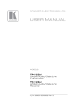
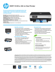
K R A ME R E LE CT R O N IC S L TD . USER MANUAL MODEL: WP-110xl UXGA /Data Line Transmitter P/N: 2900-300294 Rev 3 Contents 1 Introduction 1 2 2.1 2.2 2.3 2.4 Getting Started Achieving the Best Performance Safety Instructions Shielded Twisted Pair/Unshielded Twisted Pair Recycling Kramer Products 2 2 3 3 3 3 3.1 Overview Defining the WP-110xl UXGA/Data Line Transmitter 4 4 4 4.1 4.2 Connecting and Installing the WP-110xl Grounding the Wall Plate Wiring the TP LINE OUT RJ-45 Connector 6 7 8 5 5.1 5.2 6 Capturing the EDID Capturing the EDID from a Display Device Loading the Default EDID Technical Specifications 9 9 10 12 Figures Figure 1: WP-110xl UXGA/Data Line Transmitter Figure 2: Connecting the WP-110xl UXGA/Data Line Transmitter Figure 3: Ground Connection Figure 4: TP PINOUT Figure 5: WP-110xl US Wall Plate Figure 6: WP-110xl EU Wall Plate 5 6 7 8 10 11 WP-110xl – Contents i 1 Introduction Welcome to Kramer Electronics! Since 1981, Kramer Electronics has been providing a world of unique, creative, and affordable solutions to the vast range of problems that confront video, audio, presentation, and broadcasting professionals on a daily basis. In recent years, we have redesigned and upgraded most of our line, making the best even better! Our 1,000-plus different models now appear in 14 groups that are clearly defined by function: GROUP 1: Distribution Amplifiers; GROUP 2: Switchers and Routers; GROUP 3: Control Systems; GROUP 4: Format/Standards Converters; GROUP 5: Range Extenders and Repeaters; GROUP 6: Specialty AV Products; GROUP 7: Scan Converters and Scalers; GROUP 8: Cables and Connectors; GROUP 9: Room Connectivity; GROUP 10: Accessories and Rack Adapters and GROUP 11: Sierra Products; GROUP 12: Digital Signage; and GROUP 13: Audio, and GROUP 14: Collaboration. Congratulations on purchasing your Kramer WP-110xl UXGA/Data Line Transmitter, which is ideal for the following typical applications: Presentation and multimedia applications Long range graphics distribution for schools, hospitals, stores and security applications WP-110xl - Introduction 1 2 Getting Started We recommend that you: Unpack the equipment carefully and save the original box and packaging materials for possible future shipment Review the contents of this user manual i 2.1 Go to http://www.kramerelectronics.com/support/product_downloads.asp to check for up-to-date user manuals, application programs, and to check if firmware upgrades are available (where appropriate). Achieving the Best Performance To achieve the best performance: Use only good quality connection cables (we recommend Kramer highperformance, high-resolution cables) to avoid interference, deterioration in signal quality due to poor matching, and elevated noise levels (often associated with low quality cables) Do not secure the cables in tight bundles or roll the slack into tight coils Avoid interference from neighboring electrical appliances that may adversely influence signal quality Position your Kramer WP-110xl away from moisture, excessive sunlight and dust ! 2 This equipment is to be used only inside a building. It may only be connected to other equipment that is installed inside a building. WP-110xl - Getting Started 2.2 Safety Instructions ! 2.3 Caution: There are no operator serviceable parts inside the unit Warning: Use only the Kramer Electronics input power wall adapter that is provided with the unit Warning: Disconnect the power and unplug the unit from the wall before installing Shielded Twisted Pair/Unshielded Twisted Pair We recommend that you use Shielded Twisted Pair (STP) cable, and stress that the compliance to electromagnetic interference was tested using STP cable. There are different levels of STP cable available, and we advise you to use the best quality STP cable that you can afford. Our non-skew-free cable, Kramer BC-STP is intended for analog signals where skewing is not an issue. In cases where there is skewing, our Unshielded Twisted Pair (UTP) skew-free cable, Kramer BC-XTP, may be advantageous, and UTP cable might also be preferable for long range applications. In any event when using UTP cable, it is advisable to ensure that the cable is installed far away from electric cables, motors and so on, which are prone to create electrical interference. 2.4 Recycling Kramer Products The Waste Electrical and Electronic Equipment (WEEE) Directive 2002/96/EC aims to reduce the amount of WEEE sent for disposal to landfill or incineration by requiring it to be collected and recycled. To comply with the WEEE Directive, Kramer Electronics has made arrangements with the European Advanced Recycling Network (EARN) and will cover any costs of treatment, recycling and recovery of waste Kramer Electronics branded equipment on arrival at the EARN facility. For details of Kramer’s recycling arrangements in your particular country go to our recycling pages at http://www.kramerelectronics.com/support/recycling/. WP-110xl - Getting Started 3 3 Overview The WP-110xl is a high-performance, twisted pair (TP) transmitter for computer graphics signals over extended distances using CAT 5/6 cable. The transmitter can be connected to compatible receivers, such as, the PT-120xl, TP-122xl and the TP-126xl, (for 250m range), or the PT-120, TP-120, TP-120-od, TP-122, TP-122N, TP-122-od, TP-124, TP-124-od and the TP-124, (for 100m range). The WP-110xl comes in three models: the WP-110xl 69mm US version and the two WP-110xl 80/86mm European versions. More specifically, the WP-110xl features: Resolution up to WUXGA, 1080p HDTV compatibility up to 1080p Extended transmission range of up to 250m (820ft) with suitable devices EDID Capture copies and stores the EDID from a display device Increased level of protection against noise, spikes and interference in adverse environments 3.1 Defining the WP-110xl UXGA/Data Line Transmitter This section defines the WP-110xl. 4 WP-110xl - Overview Figure 1: WP-110xl UXGA/Data Line Transmitter # Feature 1 PC IN 15-pin HD connector Connects to the computer graphics source 2 ON LED Lights green when powered on 3 +12V/GND Terminal Block Connects to the 12V DC power supply 4 LINE OUTPUT RJ-45 Connector Connects to the twisted pair receiver, (for example, the PT-120 or TP-126xl) 5 Ground Terminal Crimp terminal connects to earth WP-110xl - Overview Function 5 4 Connecting and Installing the WP-110xl i Always switch off the power to each device before connecting it to your WP-110xl. After connecting your WP-110xl, connect its power and then switch on the power to each device. To connect the WP-110xl as illustrated in the example in Figure 2: 1. Connect the LINE OUTPUT RJ-45 connector on the rear panel of the WP110xl to the TP receiver, (for example, the PT-120 or the TP-126xl). 2. Ground the wall plate, (see Section 4.1). 3. Connect the 12V DC power supply to the 12V and GND terminals taking care to observe the correct polarity. 4. Install the WP-110xl into a suitable wall box or rack mount. 5. Connect a computer graphics source (for example, a PC) to the PC IN 15-pin HD connector. Figure 2: Connecting the WP-110xl UXGA/Data Line Transmitter 6 WP-110xl - Connecting and Installing the WP-110xl 4.1 Grounding the Wall Plate Grounding the WP-110xl is recommended. The grounding wire is connected to the rear of the chassis of the unit. The grounding screw is used to earth the unit to the ground of the building. This helps prevent static electricity from interfering with product performance. To connect the grounding to the WP-110xl as shown in Figure 3: 1. Crimp the ring-tongue terminal to the building grounding point wire. 2 (We recommend that you use a green-yellow #18 AWG wire (0.82mm ) crimped with a proper hand-tool). 2. Insert the M3x6 screw through the toothed locking washers and the ringtongue terminal in the order shown in Figure 3. 3. Insert the M3x6 screw (with the two toothed lock washers and ring-tongue terminal in place) into the grounding screw hole on the rear of the WP-110xl and tighten the screw. # Item 1 M3x6 Screw 2 M3 Toothed lock washers 3 M3 Ring tongue terminal Figure 3: Ground Connection WP-110xl - Connecting and Installing the WP-110xl 7 4.2 Wiring the TP LINE OUT RJ-45 Connector This section defines the TP pinout, using a straight pin-to-pin cable with RJ-45 connectors. EIA /TIA 568B 8 PIN 1 Wire Color Orange / White 2 Orange 3 Green / White 4 Blue 5 Blue / White 6 Green 7 Brown / White 8 Brown Figure 4: TP PINOUT WP-110xl - Connecting and Installing the WP-110xl 5 Capturing the EDID The WP-110x can capture an EDID from a connected display or can load a default EDID when no display is available or the unit cannot capture the EDID from the connected display. 5.1 Capturing the EDID from a Display Device To capture an EDID from a display: 1. Using a Philips screwdriver, remove the four screws holding the faceplate to the PCB assembly. 2. Using a short cable (for example, Kramer model number C-MGM/MGM-1), connect the PC IN input 15-pin HD connector on the WP-110xl to the 15-pin HD connector of the display and turn the display on. 3. Connect the 12V DC power adapter to the power terminal block (see Figure 1) on the WP-110xl and connect the adapter to the mains electricity. 4. Press the EDID capture button (item 1 on Figure 5 and Figure 6). The EDID status LED (item 2 on Figure 5 and Figure 6) flashes slowly several times. The new EDID is captured when the LED stops flashing and lights solid. Note: If the status LED flashes quickly for a few seconds and then stays on solid, the WP-110xl could not capture the EDID and loaded the default EDID instead. 5. Unplug the power adapter from the mains and disconnect it from the WP-110xl. 6. Replace the faceplate and secure the four screws removed in Step 1. WP-110xl - Capturing the EDID 9 5.2 Loading the Default EDID To load the default EDID: 1. Using a Philips screwdriver, remove the four screws holding the faceplate to the PCB assembly. 2. Do not connect a display to the PC IN input 15-pin HD connector. 3. Connect the 12V DC power adapter to the power terminal block (see Figure 1) on the WP-110xl and connect the adapter to the mains electricity. 4. Press the EDID capture button (item 1 on Figure 5 and Figure 6). The EDID status LED (item 2 on Figure 5 and Figure 6) flashes quickly for a few seconds and then stays on solid. 5. Unplug the power adapter from the mains and disconnect it from the WP-110xl. 6. Replace the faceplate and secure the four screws removed in Step 1. Figure 5: WP-110xl US Wall Plate 10 WP-110xl - Capturing the EDID Figure 6: WP-110xl EU Wall Plate WP-110xl - Capturing the EDID 11 6 Technical Specifications INPUT: 1 VGA / UXGA on a 15-pin HD connector OUTPUT: 1 RJ-45 LINE OUTPUT connector VIDEO RESOLUTION: Up to WUXGA, 1080p RANGE: Up to 250m (820ft) COUPLING: AC POWER CONSUMPTION: 12V DC, 70mA OPERATING TEMPERATURE: 0° to +40°C (32° to 104°F) STORAGE TEMPERATURE: -40° to +70°C (-40° to 158°F) HUMIDITY: 10% to 90%, RHL non-condensing WALL PLATE SIZE: 2 gang EU/US DIMENSIONS: 2 gang USA: 11.4cm x 3.5cm x 11.4cm (4.49" x 1.4" x 4.49", W, D, H) 2 gang Europe: 15.2cm x 3.5cm x 8.0/8.6cm (5.98" x 1.4" x 3.15/3.39", W, D, H) WEIGHT: 0.14kg (0.31lbs) approx. ACCESSORIES: Power supply OPTIONS: 19” rack adapters for EU and US wall plates; Kramer on-wall boxes Specifications are subject to change without notice at http://www.kramerelectronics.com 12 WP-110xl - Technical Specifications For the latest information on our products and a list of Kramer distributors, visit our Web site where updates to this user manual may be found. We welcome your questions, comments, and feedback. Web site: www.kramerelectronics.com E-mail: [email protected] ! P/N: SAFETY WARNING Disconnect the unit from the power supply before opening and servicing 2900- 300294 Rev: 3