1
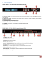
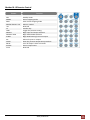
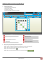
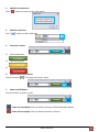
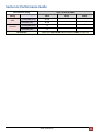
HDMI™ Matrix Switcher with IR & 3D Support User’s Guide Model no. PT‐MA‐HD44‐C Designed in Germany Made in Taiwan © 2010 PureLink GmbH. All rights reserved. www.purelink.de 1 Table of Contents Section 1: Getting Started ............................................................................................................................. 3 1. Safety and Notice ..................................................................................................................... 3 2. Introduction ............................................................................................................................. 3 3. Package Contents .................................................................................................................... 4 4. Before Installation ................................................................................................................... 4 5. Panel Descriptions ................................................................................................................... 5 6. IR Pass‐through ........................................................................................................................ 7 7. Installation ............................................................................................................................... 8 8. EDID LEARNING ........................................................................................................................ 8 Section 2: Operation appoach ....................................................................................................................... 9 Section 3: Specifications .............................................................................................................................. 20 Section 4: FAQ ............................................................................................................................................. 21 Section 5: Notice .......................................................................................................................................... 22 Section 6: Performance Guide ..................................................................................................................... 23 www.purelink.de 2 Section 1: Getting Started 1. Safety and Notice Please read all of these instructions carefully before you use the device. Save this manual for future reference. The PT‐MA‐HD44‐C HDMI™ Matrix Switcher with IR & 3D Support has been tested for conformance to safety regulations and requirements, and has been certified for international use. However, like all electronic equipments, the PT‐MA‐HD44‐C should be used with care. Please read and follow the safety instructions to protect yourself from possible injury and to minimize the risk of damage to the unit. Follow all instructions and warnings marked on this unit. Do not attempt to service this unit yourself, except where explained in this manual. Provide proper ventilation and air circulation and do not use near water. Keep objects that might damage the device and assure that the placement of this unit is on a stable surface. Use only the power adapter and power cords and connection cables designed for this unit. Do not use liquid or aerosol cleaners to clean this unit. Always unplug the power to the device before cleaning. Introduction Introduction 2. Introduction The PT‐MA‐HD44‐C HDMI™ Matrix Switcher with IR & 3D Support provides the most flexible and cost effective solution in the market to route high definition video sources plus multi‐channel (up to 7.1‐channel) digital audio from any of the four HDMI sources to the remote displays at the same time. Through only one low cost Cat‐5/5e/6 LAN cable, not only high quality video and audio can be transmitted to the display sites, but also users can switch among four HDMI sources using the push‐in button or remote control. Furthermore, the built‐in IR extension function makes users at display site access the DVD player, PS3 or any HDMI supported devices directly! — Support HDMI Deep Color & full 3D — HDCP compliant — Allows any source to be displayed on multiple displays at the same time — Allows any HDMI display to view any HDMI source at any time — Supports 7.1 channel digital audio — Supports default HDMI EDID and learns the EDID of displays — The matrix master can switch every output channels to any HDMI inputs by push‐in button, IR remote control, RS‐232 control, and Ethernet control www.purelink.de 3 — Allows controlling local HDMI sources such as DVD and TiVo by attached IR extender from remote receiver to matrix master — Extends video signal up to 35m (115 feet) over single CAT.X at 1080p and likely longer with better HDMI source device (such as PS3), better grade HDMI display (such as Sony X‐series HDTV), and better quality solid CAT6 cable — Easy installation with rack‐mounting and wall‐mounting designs for master and receiver respectively — Fast response time – 2~5 seconds for channel switch 3. Package Contents Before you start the installation of the switch, please check the package contents. — PT‐MA‐HD44‐C — Matrix Receiver — Rack‐mounting ear set — IR Remote control* — IR Blaster* — IR Receiver — Power supply unit (+5VDC, 4A) — Power supply unit (+5VDC, 2A) — Installation software CD — User’s Guide x1 x4 x1 x1 x1 x5 x1 x4 x1 x1 * Additional IR remote controllers and IR blasters can be purchased as optional accessories to control the HDMI sources located separately. 4. Before Installation Put the product in an even and stable location. If the product falls down or drops, it may cause an injury or malfunction. Don’t place the product in too high temperature (over 50°C), too low temperature (under 0°C) or high humidity. Use the DC power supply unit with correct specifications. If inappropriate power supply is used then it may cause a fire. Do not twist or pull by force ends of the cable. It can cause malfunction. www.purelink.de 4 5. Panel Descriptions FRONT PANEL — PT‐MA‐HD44‐C, transmitting unit (TX) 1. Input Push Button: Front panel push buttons used to select the number of input source & LED display for input channels 2. Output Push Button: Front panel push buttons used to select the number of display channel & LED display for output ports 3. Push Button: Select the needed function 4.SET: To confirm the function which had been selected. 5. IR SENSOR: IR sensor for receiving the IR commands from IR remote 6. VFD window REAR PANEL — PT‐MA‐HD44‐C, transmitting unit (TX) 7. Power: Power control 8. RS‐232: RS‐232 control port 9. Ethernet: Ethernet control port 10. INPUT 1‐3: HDMI inputs 11. INPUT 4 & EDID Port: HDMI input and EDID port for learning EDID from display 12. Output Port 1‐4: RJ‐45 outputs for each output channel 13. IR Blaster 1‐4: 3.5mm IR blaster socket for individual HDMI source control 14. System IR Receiver: Ext. IR receiver 15. All IR Output: 3.5mm IR blaster socket for HDMI source control on all 4 inputs 16. +5V DC: 5V DC power jack www.purelink.de 5 FRONT PANEL — PT‐MA‐HD44‐C, receiving unit (RX) Signal Level: Adjust the 8‐level equalization control to the received HDMI signals. The HDMI signal level varies from strongest (0) to weakest (7) for respective transmission length from longest possible range to short distance. Please adjust the signal level from strongest to weakest and stop turning the rotary switch whenever the audio/video is playing normally. Inappropriate signal level setting may cause overpowering issue that would shorten the product life significantly! HDMI OUT: Connect to HDTV with a HDMI cable IR RECEIVER: Plug in IR receiver IR Blaster: Plug in IR blaster REAR PANEL — PT‐MA‐HD44‐C, receiving unit (RX) +5V DC: Connect to 5V DC power supply. HDMI SIGNAL IN: Plug in a Cat.X cable. www.purelink.de 6 6. IR Pass‐through IR Extenders IR Blaster IR Receiver IR Sockets PT‐MA‐HD44‐C All IR Out: The default location for IR blaster to transmit all IR command signals received from any of the four remote receivers to all of the HDMI sources. IR BLASTER 1‐4: IR blaster connected here can only transmit IR command signals from the remote receivers that are setting at respective input channel from 1 to 4. System IR: Receives IR commands from remote control PT‐E‐HD10 IR BLASTER: IR control on individual display device IR RECEIVER: IR receiver connected here can receive all IR command signals from the IR remote controls of PT‐MA‐HD44‐C and all other HDMI source devices. CAUTION! Incorrect placement of IR Blaster and Receiver may result in the failure of the IR extenders. Please check carefully before plugging in the IR extender to the respective IR sockets. Warranty will not cover the damage. Definition of IR Earphone Jack IR Blaster IR Receiver You can buy any IR extension cables in the market that are compatible to the definition of the IR sockets for the matrix if necessary for replacement use. However, IR cables longer than 2m (6‐ft) may not work. www.purelink.de 7 7. Installation — Connect all sources to HDMI Inputs on the 4x4 HDMI over CAT.X matrix master PT‐MA‐HD44‐C. — Connect each CAT.X output port on the PT‐MA‐HD44‐C to respective CAT.X input on the remote receiver PT‐E‐HD10. — Connect each HDMI output on receiver to HDMI displays. — Connect IR blaster to the PT‐MA‐HD44‐C and direct the IR blaster to point towards the built‐in IR receiver of the HDMI source devices. — Connect the +5V 4A DC power supply to the PT‐MA‐HD44‐C and +5V 2A DC power supply to the receivers — Power on all HDMI sources and displays. — Dial the 8‐level rotary control switch to adjust the HDMI signal level until the picture and sound are clear. It is recommended to dial from weakest to strongest to find the optimal visual experience 8. EDID LEARNING The EDID learning function is only necessary whenever you encounter any display on the HDMI output port that cannot play audio and video properly. Because the HDMI source devices and displays may have various level of capability in playing audio and video, the general principle is that the source device will output the lowest standards in audio format and video resolutions to be commonly acceptable among all HDMI displays. In this case, a 720p stereo HDMI signal output would be probably the safest choice. Nevertheless, the user can force the matrix to learn the EDID of the lowest capable HDMI display among others to make sure all displays are capable to play the HDMI signals normally. There are eight embedded default EDID as below, — Full‐HD(1080p@60)‐24bit 2D & 2ch — Full‐HD(1080p@60)‐24bit 2D & 7.1ch — Full‐HD(1080p@60)‐24bit 3D & 2ch — Full‐HD(1080p@60)‐24bit 3D & 7.1ch — HD(1080i@60)(720p@60)‐24bit 2D & 2ch — HD(1080i@60)(720p@60)‐24bit 2D & 7.1ch — Full‐HD(1080p@60)‐36bit 2D & 2ch — Full‐HD(1080p@60)‐36bit 2D & 7.1ch www.purelink.de 8 Section 2: Operation approach Mode Selection Pressing UP(↑) or DOWN(↓) button to select among 4 different modes – Save Mapping Mode, Preset Mapping Mode, Default EDID Mode, EDID Learning Mode, and Status Mode 1. 1) 2) 3) 4) 2. 1) Save Mapping Mode Pushing “Left (←)”button, to enter the Save Mapping Mode. Use the “Right (→)“ input push button to get into the selection of the mapping configuration, and use “UP (↑) & DOWN (↓)” (1~8) to choose which set you want to save current input/output mapping After you select the desired mapping configuration number, the number will be twinkled. Then, press the SET button, the setting will be saved successfully. press LEFT(←) button to go back to pre‐layer Preset Mapping Mode Pushing “Left (←)”button, and use DOWN (↓) button to enter the Preset Mapping Mode. www.purelink.de 9 2) Use the “Right (→)“ input push button to get into the selection of the saved mapping configuration, and use “UP (↑) & DOWN (↓)” (1~8) to choose which mapping you want 3) After you select the desired mapping configuration number, the number will be twinkled. Then, press the SET button, the device will show the selected mapping. 4) press LEFT(←) button to go back to pre‐layer 3. Default EDID Mode 1) Select Default EDID Mode and press RIGHT(→) button to enter this mode 2) Press UP(↑) and DOWN(↓) button to select the default EDID mode(1~8) 3) Press LEFT(←) button to go back to pre‐layer 4) Press UP(↑) and DOWN(↓) button to select which input will be applied 5) Press SET button to confirm, and VFD will show OK or FAIL after setting 6) Or press LEFT(←) button to go back to pre‐layer 4. EDID Learning Mode (OUTOUT EDID) 1) Select EDID Learning Mode and press RIGHT(→) button to enter this mode 2) Press UP(↑) and DOWN(↓) button to select which input will learn the EDID from EDID port 3) Press SET button to confirm; or press LEFT(←) button to go back to pre‐layer 4) If confirmed, VFD will show SUCCEED or FAIL after learning www.purelink.de 10 Method B: IR Remote Control Button ON OFF PRESET SAVE Number buttons 1‐9 +10 To TAKE SWITCH DEFAULT EDID LEARN ALL CLEAR MUTE STATUS F1‐F4 Function Power on the matrix switcher Standby mode Preset mapping mode Save current mapping mode Select a number Reserved Transfer key Trigger the previous setting Begin input and output selection Begin default EDID selection Begin EDID learning from one output Select all inputs or outputs Clear the previous IR operation procedure Turn off output’s video and audio Preset output status Reserved www.purelink.de 11 Operation IN/OUT Switch Procedure Switch + number(input) + To + number(output) + Take 1.Press “SWITCH” button 2.Press number key “3” to select Input Ex: Input 3 3.Press “To” button To Output 4 4.Press number key “4” to select Output 5.Press “TAKE” button Switch + number(input) + To + All(output) + Take 1.Press “SWITCH” button 2.Press number key “3” to select Input Ex: Input 3 3.Press “To” button To Output All 4.Press “ALL” to select All Output 5.Press “TAKE” button Output Status Status + number(output) + Take 1.Press “STATUS” button Ex: Output 4 2.Press number key “4” to select Output (Input 2) 3.Press “TAKE” button Factory Reset Status + Status + Status + Take 1.Press “STATUS” button 2.Press “STATUS” button 3.Press “STATUS” button 4.Press “TAKE” button Learn default EDID Default EDID + number(1‐8 default EDID) + To + number(input) + Take 1.Press “DEFAULT EDID” button 2.Press number key “2” to select default EDID Ex: Default EDID 2 3.Press “To” button Input 3 4. Press number key “3” to select Input 5.Press “TAKE” button Default EDID + number(output) + To + All(input) + Take 1.Press “DEFAULT EDID” button 2.Press number key “2” to select default EDID Ex: Default EDID 2 3.Press “To” button Input All 4.Press “ALL” to select All Input 5.Press “TAKE” button www.purelink.de 7‐Segment LED ‐ ‐ ‐ 3 ‐ 3 4 3 4 3 ‐ ‐ ‐ 3 ‐ 3 A 3 4 3 ‐ ‐ 4 ‐ 4 2 ‐ ‐ d ‐ d d 1 1 E d 2 d 2 d 2 3 0 F 0 (success) F(fail) E d 2 d 2 d 2 A 0 F 0 (success) F(fail) 12 Operation Learn EDID Port EDID Procedure Learn + 4(EDID Port) + To + number(input) + Take 1.Press “LEARN” button 2.Press number key “4” to select EDID Port Ex: Learn EDID Port 3.Press “To” button Input 3 4. Press number key “3” to select Input 5.Press “TAKE” button Learn + 4(EDID Port) + To + All(input) + Take 1.Press “LEARN” button 2.Press number key “4” to select EDID Port Ex: Learn EDID Port 3.Press “To” button Input All 4.Press “ALL” to select All Input 5.Press “TAKE” button Save Current Mapping Save + number(1‐8 storage site) + Take 1.Press “SAVE” button Ex: Save current mapping to 5 2.Press number key “5” to select the storage site Preset Mapping 3.Press “TAKE” button Preset + number(1‐8 storage site) + Take 1.Press “PRESET” button Ex: Preset saved mapping from 5 2.Press number key “5” to select the storage site Mute Output 3.Press “TAKE” button Switch + Mute + To + number(output) + Take 1.Press “SWITCH” button 2. Press “MUTE” button Ex: Mute Output 3 3.Press “To” button 4. Press number key “3” to select Output 5.Press “TAKE” button Switch + Mute + To + All(output) + Take 1.Press “SWITCH” button 2. Press “MUTE” button Ex: Mute All Output 3.Press “To” button 4. Press “ALL” to select all output 5.Press “TAKE” button 7‐Segment LED E L 4 L 4 L 4 3 0 F 0 (success) F(fail) E L 4 L 4 L 4 A 0 F 0 (success) F(fail) d ‐ 5 ‐ P ‐ 5 ‐ ‐ ‐ ‐ 0 ‐ 0 3 0 3 0 ‐ ‐ ‐ 0 ‐ 0 A 0 4 0 www.purelink.de 13 Method C: Software Control through RS‐232 port 1. System Requirement 1) OS Information: MS WinXP/7 2) Baud rates: 9600 3) Software size: 3 MB 4) Minimum RAM requirement: 256 MB 1 7 6 2 3 9 8 11 4 5 10 12 1 2 3 4 5 6 FW/SW Version Button COM Port Selection Connection Status Connect/Disconnect Button Power On/Off Button EDID Button 7 8 9 10 11 12 Firmware Update Button Network Button Mapping Button Default Reset Button In/Out Switch Button Mute Output Button 2. Step by step for connecting matrix and controller Step1: Use RS‐232 cable to connect the RS‐232 port on matrix and controller Step2: Open the software and then choose the correct com port Step3: Click connection button “ ” Step4: Make sure the connection status is on connected status “ ” www.purelink.de 14 3. FW/SW Version Button Click “ ” button to show version information 4. COM Port Selection Click “ ” button to select COM Port 5. Connection Status 1) Connected Status: 2) Connecting Status: 3) Disconnected Status: 6. Connect/Disconnect Button Click this button “ ” to change connection status 7. Power On/Off Button Click this button to power on/off “ ” Power on status(Blue): Click this button to power off device(Standby Mode) “ ” Power off status(Red): Click this button to power on device www.purelink.de 15 8. 1) a) b) c) 2) a) b) 3) a) b) c) 4) a) EDID Button Learn EDID from Default Select Default EDID(1‐8 Default EDID) Select Input Click “Learn” button to learn default EDID Load EDID File to Input Select Input Click “Load” button to select the EDID file Learn EDID From Display Select EDID Port Select Input Click “Learn” button to learn display EDID Create EDID File Click “Create” button to create EDID file www.purelink.de 16 b) c) 5) a) b) Select the EDID content Click “Save EDID on Computer” to save the generated EDID as a file c) Click “Save As” to save the read EDID as a file on computer View EDID Content Select Input, or From File Click “View” button to read the EDID and analysis www.purelink.de 17 9. Firmware Update Button Click “Load File” to select the firmware file which you want to update Click “Break” button Quickly remove and reconnect the power input connector Click “Start” button to begin the firmware update 10. Network Button 1) 2) 3) 4) 1) 2) 3) 4) 5) 11. Click “Read From Device” to read the device IP address Select “Ethernet” and then will be a pop‐up windows Key in the device IP address to the pop‐up windows Close the pop‐up windows Click the connected button to connect 1) a) b) Save Mapping: Select Mapping(1‐8) Click “Save” button to save current mapping Mapping Button www.purelink.de 18 2) Preset Mapping: a) Select Mapping(1‐8) b) Click “Recall” button to recall previous mapping which are saved 3) Rename Mapping: a) Rename the mapping(Mapping1‐Mapping8) b) Click “Confirm” button to confirm the change 12. Default Reset Button Click this button to do factory default reset The default reset process will take about 80~90 seconds 13. In/Out Switch Button Click the button on the checkerboard to select Input & Output port User can click the input number button to let all outputs select the same input Ex: All outputs select input 3 14. Mute Output Button Click the circle button to turn off output’s video and audio Ex: Mute Output 2 www.purelink.de 19 Section 3: Specifications Item Units Unit Description HDMI Compliance HDCP Compliance Video Bandwidth Supported Resolutions Audio support Description Transmitting unit of PT‐MA‐HD44‐C Receiving unit of PT‐E‐HD10 Transmitter Receiver HDMI Deep Color & full 3D Yes Single‐link 225MHz [6.75Gbps] 480i / 480p / 720p / 1080i / 1080p60 Surround sound (up to 7.1ch) or stereo digital audio HDMI over CAT5 transmission range Equalization Input TMDS Signal Input DDC Signal ESD Protection Input Output HDMI Input selection HDMI source control IR remote control HDMI connector RJ‐45 connector RS‐232 connector 3.5mm connector Full HD (1080p): 35m (115ft) [CAT.X] HD (720p/1080i): 50m (165ft) [CAT.X] None 8 Level Digital Control 1.2 Volts (peak‐to‐peak) 5 Volts (peak‐to‐peak, TTL) −Human body model — ±19kV (air‐gap discharge) & ±12kV (contact discharge) −Core chipset — ±8kV 4x HDMI / 1x RS‐232 / 1x Ethernet 1x RJ‐45 / 1x IR socket for IR receiver 1x IR socket for IR receiver 4x RJ‐45 / 1x HDMI / 5x IR socket for IR blaster 1x IR socket for IR blaster Push‐in button / IR remote control / IR remote control RS‐232 control / Ethernet control Controllable via IR pass‐through from IR receiver at RX to IR blaster at TX Electro‐optical characteristics: = 25° / Carrier frequency: 20‐60kHz Type A [19‐pin female] WE/SS 8P8C DE‐9 [9‐pin D‐sub female] Earphone jack for IR blaster [All IR Out] IR control on all source devices Earphone jack for IR receiver [IR1~IR4] IR control on individual source [IR] Receives IR commands from remote device control Earphone jack for IR receiver [System IR] Receives IR commands from remote control Environmental Operating Temperature Storage Temperature Relative Humidity 0~40°C [32~104°F] ‐20~60°C [‐4~140°F] 20~90% RH (no condensation) www.purelink.de 20 Section 4: FAQ Q The quality of output video is not good enough, how can I do? A Please adjust the 8‐level equalization on the receiver units. The HDMI signal level varies from 0 (strongest) to 7 (weakest) for respective transmission length from longest possible range to short distance. It is recommended to switch from 7 to 0 to find the optimal visual experience. Q Can I use any kind of LAN cable? A Please check the NOTICE section for more information about how to pick up a suitable cable. Q Can every TV work with the HDMI matrix? A Basically, the answer is YES. But if your TV can not support 1080p, please refer the EDID LEARNING section to learn EDID from your TV. Q What is EDID? Why do I need to learn EDID? A EDID contains the whole information of the display such as the resolution and audio setting which this display can support. Therefore, based on the EDID information, media player will pick up the most suitable resolution and audio setting to the display. In order to faithfully transmit the EDID information from display to the media player, learning EDID from display to this device is necessary. Q What should I do to learn EDID for the matrix? A Due to the limitation of HDMI, the source device can only output one format of video and audio. In other words, the source device cannot output 720p and 1080p video at the same time, or output stereo and surround sound at the same time. Therefore, you may need to manually setup each HDMI input for desirable audio/video output format. The mechanism of EDID Learning is to pick up the HDMI display with the lowest capability among the ones you would use for this input source. For example, if user would like to play the Input‐2 upon output‐2, output‐3 and output‐4, and only output‐3 cannot support 1080p [support up to 720p only], please learn the EDID from the display connected to the output‐3 at the Input‐2 port. Of course, if outpt‐3 would get the HDMI signals from every HDMI input, please learn EDID information from output3 to all four HDMI inputs. For more information about EDID Learning, please refer to EDID LEARNING section. Q My TV can support 1080p, but why there is no audio? A The factory default EDID of this device is 1080p & 2ch audio. However, there would be a problem after you change to use 1080p & 7.1ch if the TV cannot support 7.1ch audio. Please use the default EDID, 1080p & 2ch audio. Q When I set an audio amplifier (AV receiver) between TV and the matrix to extract 7.1ch audio, but why there is still no audio? A Basically, the default EDID of the chosen input can support 7.1ch audio, but the problem is that the EDID of the amplifier still cannot match the default setting. Therefore, the best method is to learn EDID from the amplifier directly. Please refer to EDID LEARNING section and follow the steps to learn the EDID. When learning EDID from the amplifier, user just needs to connect the matrix and amplifier. Please don't connect HDMI cable between amplifier and TV when the EDID learning is proceeding. Q When I play the same content upon multi‐displays, why only the TV equipped with amplifier can have 7.1ch audio, and the others don't have 7.1ch audio even no stereo? A Due to the limitation of HDMI, the source only can choose one video and one audio format to play, which can be either 1080p and 7.1ch or 1080p and stereo audio. It means when the user sets the matrix at 1080p and 7.1ch, the source will only play the content under this format. Therefore if the TV cannot decode 7.1ch audio, there is definitely no audio. www.purelink.de 21 Section 5: Notice 1. If the DVI or HDMI device requires the EDID information, please use EDID Reader/Writer to retrieve and provide DVI/HDMI EDID information. 2. All HDMI over CAT5 transmission distances are measured using Belden 1583A CAT5e 125MHz LAN cable and ASTRODESIGN Video Signal Generator VG‐859C & VG‐870B. 3. The transmission length is largely affected by the type of LAN cables, the type of DVI sources, and the type of DVI display. The testing result shows solid LAN cables (usually in bulk cable 300m/1000ft form) can transmit a lot longer signals than stranded LAN cables (usually in patch cord form). Shielded STP cables are better suited than unshielded UTP cables. A solid UTP CAT5e cable shows longer transmission range than stranded STP CAT6 cable. For long extension users, solid LAN cables are the only viable choice. 4. EIA/TIA‐568‐B termination (T568B) for LAN cables is recommended for better performance. 5. To reduce the interference among the unshielded twisted pairs of wires in LAN cable, one can use shielded LAN cables to improve EMI problems, which is worsen in long transmission. 6. Because the quality of the LAN cables has the major effect on how long the transmission limit can achieve and how good is the received picture quality, the actual transmission range is subject to one’s choice of LAN cables. For desired resolutions greater than 1080i or 1280x1024, a Cat‐6 cable is recommended. 7. If your HDMI display has multiple HDMI inputs, it is found that the first HDMI input [HDMI input #1] generally can produce better transmission performance among all HDMI inputs. 8. Additional IR remote controls and IR blasters can be purchased as optional accessories to control the HDMI sources located separately. www.purelink.de 22 Section 6: Performance Guide Performance rating Wiring Solid Stranded Type of CAT5/6 cable Shielding CAT5 Unshielded (UTP) Shielded (STP) CAT5e CAT6 Unshielded (UTP) Shielded (STP) Termination Please use EIA/TIA‐568‐B termination (T568B) at any time www.purelink.de 23 www.purelink.de 24 www.purelink.de 25