1
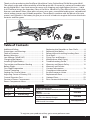
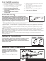
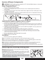
Ultra Micro DH 98 Mosquito Mk VI Instruction Manual Bedienungsanleitung Manuel d’utilisation Manuale di Istruzioni NOTICE All instructions, warranties and other collateral documents are subject to change at the sole discretion of Horizon Hobby, Inc. For up-to-date product literature, visit www.horizonhobby.com and click on the support tab for this product. Meaning of Special Language: The following terms are used throughout the product literature to indicate various levels of potential harm when operating this product: NOTICE: Procedures, which if not properly followed, create a possibility of physical property damage AND little or no possibility of injury. CAUTION: Procedures, which if not properly followed, create the probability of physical property damage AND a possibility of serious injury. WARNING: Procedures, which if not properly followed, create the probability of property damage, collateral damage, and serious injury OR create a high probability of superficial injury. WARNING: Read the ENTIRE instruction manual to become familiar with the features of the product before operating. Failure to operate the product correctly can result in damage to the product, personal property and cause serious injury. This is a sophisticated hobby product. It must be operated with caution and common sense and requires some basic mechanical ability. Failure to operate this Product in a safe and responsible manner could result in injury or damage to the product or other property. This product is not intended for use by children without direct adult supervision. Do not attempt disassembly, use with incompatible components or augment product in any way without the approval of Horizon Hobby, Inc. This manual contains instructions for safety, operation and maintenance. It is essential to read and follow all the instructions and warnings in the manual, prior to assembly, setup or use, in order to operate correctly and avoid damage or serious injury. Additional Safety Precautions and Warnings As the user of this product, you are solely responsible for operating in a manner that does not endanger yourself and others or result in damage to the product or the property of others. This model is controlled by a radio signal subject to interference from many sources outside your control. This interference can cause momentary loss of control so it is advisable to always keep a safe distance in all directions around your model, as this margin will help avoid collisions or injury. Age Recommendation: Not for children under 14 years. This is not a toy. • Always keep a safe distance in all directions around your model to avoid collisions or injury. This model is controlled by a radio signal subject to interference from many sources outside your control. Interference can cause momentary loss of control • Always operate your model in open spaces away from full-size vehicles, traffic and people. • Always carefully follow the directions and warnings for this and any optional support equipment (chargers, rechargeable battery packs, etc.). • Always keep all chemicals, small parts and anything electrical out of the reach of children. • Always avoid water exposure to all equipment not specifically designed and protected for this purpose. Moisture causes damage to electronics. • Never place any portion of the model in your mouth as it could cause serious injury or even death. • Never operate your model with low transmitter batteries. 2 EN Thank you for purchasing the ParkZone Ultra Micro Series DeHavilland DH 98 Mosquito Mk VI. The speed, range and maneuverability of the Mosquito Mk. VI earned it a variety of combat roles during World War II. Low-level reconnaissance, anti-shipping and night fighter missions – it did it all. ParkZone brings the legendary “Mossie” to life in a Bind-N-Fly Ultra Micro Series replica that features scale details like a camo paint scheme, nose guns, removable landing gear, steerable tail wheel, exhaust covers and 3-blade propellers. These details combine with the power of its twin motors and 250mAh Li-Po battery to give you a one-of-a-kind twin-engine ultra micro that looks fantastic and flies great. Table of Contents Additional Safety Precautions and Warnings .....................................2 Table of Contents ......................................................3 Battery Warnings .......................................................4 Low Voltage Cutoff (LVC) .......................................4 Charging the Battery ...............................................5 Installing Flight Battery ...........................................6 Transmitter and Receiver Binding ......................6 Before Flight ................................................................6 First Flight Preparation ............................................7 Control Centering .....................................................7 Settings for Control Horns .....................................7 Adjusting Center of Gravity (CG)..........................7 Control Direction Test .............................................8 Service of Power Components ............................9 Power Component Access .....................................9 Mosquito Specifications Wingspan 20.5 in (520mm) Length 15.2 in (387mm) Weight 2.60 oz (74 g) Replacing the Propeller or Gear Shaft................9 Replacing the Motor.................................................9 Removing and Installing Landing Gear.............9 Dual Rates ................................................................. 10 Flying Tips and Repairs ......................................... 10 Maintenance After Flying .................................... 10 Troubleshooting Guide ........................................ 11 Warranty and Repair Policy ................................. 12 Warranty and Service Contact Information .............................................. 13 Compliance Information for the European Union........................................ 13 Replacement Parts ................................................. 51 Optional Parts .......................................................... 52 Parts Contact Information ................................... 53 Mosquito Features Bind-N-Fly® Aircraft Onboard Electronics SpektrumTM AR6400T Receiver/Servos/ESC Battery 250mAh 3.7V Li-Po Charger 1S 3.7V Li-Po Battery Charger Transmitter DSM Aircraft Transmitter Installed Included Included Sold Separately To register your product online, go to www.parkzone.com EN 3 Battery Warnings WARNING Never leave charging Batteries unattended. WARNING Always charge Batteries away from flammable materials. WARNING Never charge Batteries outside safe temperature range. WARNING Never charge Batteries outside recommended levels. WARNING Never charge damaged Batteries. WARNING Store Batteries safely. The Battery Charger (EFLC1007) included with the Mosquito BNF has been designed to safely charge the Li-Po battery. CAUTION: All instructions and warnings must be followed exactly. Mishandling of Li-Po batteries can result in a fire, personal injury, and/or property damage. • By handling, charging or using the included Li-Po battery you assume all risks associated with lithium batteries. • If at any time the battery begins to balloon or swell, discontinue use immediately. If charging or discharging, discontinue and disconnect. Continuing to use, charge or discharge a battery that is ballooning or swelling can result in fire. • Always store the battery at room temperature in a dry area for best results. • Always transport or temporarily store the battery in a temperature range of 40-120º F. Do not store battery or model in a car or direct sunlight. If stored in a hot car, the battery can be damaged or even catch fire. • Never exceed the recommended charge rate. • NEVER USE A Ni-Cd OR Ni-MH CHARGER. Failure to charge the battery with a compatible charger may cause fire resulting in personal injury and/or property damage. • Never discharge Li-Po cells to below 3V under load. • Never cover warning labels with hook and loop strips. Low Voltage Cutoff (LVC) When a Li-Po battery is discharged below 3V, it will not hold a charge. The Mosquito ESC protects the flight battery from over-discharge using Low Voltage Cutoff (LVC). Before the battery charge decreases too much, LVC removes power supply from the motors. Power to the motors quickly decreases and increases, showing some battery power is reserved for flight control and safe landing. When the motor power decreases then increases, please land the aircraft immediately and recharge the flight battery. Disconnect and remove the Li-Po battery from the aircraft after use to prevent trickle discharge. Before storage, charge the Li-Po battery to full capacity. During storage make sure battery charge does not go below 3V per cell. NOTICE: Repeated flying to LVC will damage the battery. 4 EN Charging the Battery Only charge the battery with the included Celectra™ 1-Cell 3.7V Variable Rate DC Li-Po Charger. Please familiarize yourself thoroughly with the Battery Warnings and Guidelines section before continuing. CAUTION: Never connect Li-Po batteries to a charger when charger is not powered. Never leave adapter/ power supply or charger unattended when power is connected. A 6-volt battery, a 12-volt battery, a 12-volt AC/DC power supply or an E-flite 6V, 1.5-Amp AC/DC Power Supply may be used with this charger. ALWAYS use a proper AC to DC adapter/power supply when powering the charger from an AC outlet. The Battery Charging Process 1. Charge only batteries that are cool to the touch and are not damaged. Make sure battery is NOT damaged e.g., swollen, bent, broken or punctured. 2. Put the included charger cord (EFLUC1008) output plug in power socket of the Variable Rate Charger. 3. Connect the charger cord (EFLUC1008) clips to correct poles on a fully charged 6-or 12-volt battery (battery not included). Attach red clip to positive (+) pole and black clip to negative (-) pole. An LED on the charger will illuminate. 4. Press + or - buttons (buttons to the right (+) and left (-) of the large middle button) to make charger LEDs show at the 0.7-amp mark (included 250mAh battery requires 0.7 amps). 5. Align red dots on flight battery and charger connector and connect battery to charger connector. 6. Press Start button on the charger (large middle button). 7. When flight battery is fully charged, LEDs will illuminate, sweeping from side to side. 8. Immediately remove fully charged flight battery from the charger. CAUTION: Overcharging a battery can cause a fire. WARNING: Failure to use the proper charger for a Li-Po battery can result in serious damage, and if left charging long enough, will cause a fire. ALWAYS use caution when charging Li-Po batteries. LED Functions under normal operation • Single Solid LED ......................................................................................................Shows Charge Current • Single LED Flashing ...............................................................................................Charging • Multiple LEDS Flashing ........................................................................................Charge Almost Complete • LEDs Sweeping Side to Side ...............................................................................Charge Complete EN 5 Installing Flight Battery 1. Remove hatch. 2. Correctly align red dots and attach power connector to battery. 3. Install battery in model using hookand-loop strips then install hatch. Note: Always disconnect the Li-Po from the receiver/ESC of the airplane when not flying. Failure to do so will render the battery unusable. 1 2 3 Transmitter and Receiver Binding Binding is the process of programming the receiver of the control unit to recognize the GUID (Globally Unique Identifier) code of a single specific transmitter. You need to ‘bind’ your chosen Spektrum DSM® technology equipped aircraft transmitter to the receiver for proper operation. Note: For a list of compatible DSM transmitters, please visit www.bindnfly.com. Note: When using a Futaba transmitter with a Spektrum DSM module, you will need to reverse the throttle channel. Binding Procedure 1. Refer to your transmitter’s unique instructions for binding to a receiver. 2. Make sure the flight battery is disconnected from the aircraft. 3. Power off the transmitter and move the transmitter more than 2 feet (50 cm) from the aircraft. Keep away from large metal objects (vehicles, etc.) while binding. 4. Connect the flight battery in the aircraft. The receiver LED will begin to flash rapidly. (Typically after 5 seconds). Note: Receiver LED is visible in the fuselage when the nose cone is removed. 5. Make sure transmitter controls are neutral and throttle and throttle trim are in low position. 6. Put your transmitter into bind mode. Refer to your transmitter’s manual for binding button or switch instructions. 7. After 5 to 10 seconds, the receiver status LED will become solid, indicating the receiver is bound to the transmitter. Note: If the LED does not go to a solid light, refer to Troubleshooting Guide at back of manual. Before Flight 1 2 Lower throttle and throttle trim to lowest settings Power on Transmitter 3 Connect flight battery and attach to hook and loop strip. Wait 5 Seconds Continuous LED Note: Always disconnect the Li-Po from the receiver/ESC of the aircraft when not flying. Failure to do so will render the battery unusable. CAUTION: When armed, the motors will turn the propellers in response to any throttle movement. When the aircraft does not respond, you may need to bind. 6 EN First Flight Preparation 1. Remove and inspect box contents. 2. Read this instruction manual thoroughly. 3. Install the flight battery in the airplane (once it has been fully charged). 4. Bind aircraft to your transmitter. 5. Make sure carbon fiber control rods move freely. 6. Make sure flight control surfaces are centered. 7. Perform the Control Direction Test with the transmitter. 8. Adjust flight controls and transmitter. 9. Adjust battery position for Center of Gravity (CG). 10. Perform a radio system Range Check. 11. Find a safe and open area. Control Centering Before first flights, or in the event of an accident, make sure the flight control surfaces are centered. Adjust linkages mechanically if control surfaces are not centered. Use of the transmitter trims may not correctly center the aircraft control surfaces due to the mechanical limits of linear servos. 1. Make sure control surfaces are neutral when the transmitter controls and trims are centered. Where possible, transmitter sub-trim must be set to 0. 2. When needed, use a pair of pliers to carefully bend the metal of the linkage (see illustration). 3. Make the U-shape narrower to make the linkage shorter. Make the U-shape wider to make the linkage longer. Note: Do not use Sub-Trim to adjust the center position of the servo, and never set Travel Adjust values above 100%. Ultra Micro servos reach maximum travel at 100%. Increasing the value above 100% will NOT result in more travel, but can cause the servo to lock and will result in poor flight characteristics or a crash. Note: Linkages for ailerons are inside nacelles. Aileron linkages are smaller and may never need adjustment. Settings for Control Horns The picture here shows factory settings for linkages on control horns. After flying, if you want more or less control throw, carefully adjust linkage positions for desired control response. (Picture not to scale.) Elevator Rudder Adjusting Center of Gravity (CG) Install the flight battery and do a check for CG 38mm rearwards from the leading edge of the wing at the fuselage. 38mm Adjust CG by moving flight battery. EN 7 Control Direction Test Bind your aircraft and transmitter before doing these tests. Move the controls on the transmitter to make sure aircraft control surfaces move correctly. Note: Not to scale. Aileron Elevator Rudder 8 EN Service of Power Components CAUTION: DO NOT handle a motor, propeller or ESC while the flight battery is connected to the model. Personal injury could result. Power Component Access 1. Remove landing gear from nacelle. 2. Carefully remove glued (foam-safe CA) exhaust covers (marked right (R) and left (L)) from nacelle. 3. Cut tape on left and right sides of the nacelle where upper and lower nacelle parts meet. Tape can remove paint. 4. Carefully remove lower nacelle from upper nacelle (motor wires are attached to the wing and the control board in the fuselage). A B C D Note: Wiring not shown. Removing the Propeller, Propeller Shaft or a Motor. 1. Hold prop shaft (C) using needle-nose pliers or hemostats. 2. Remove the propeller (B) by turning it counterclockwise (looking from front of model) on the threaded shaft. When you can reach the gear on the shaft, hold the gear and turn the propeller to remove the propeller. 3. Carefully remove glued (foam-safe CA) spinnner (A) from propeller. You may need to cut glue and foam from the propeller. 4. Hold the nut (D) on the shaft using needle-nose pliers or hemostats. 5. Turn shaft clockwise (looking from front of model) to remove the nut and washer. 6. Gently pull shaft from gearbox. Make sure washer and 2 bushings are not lost when shaft is removed from gearbox. 7. Remove glued (foam-safe CA) gearbox from nacelle. 8. Remove motor from gearbox. Installation 1. Reverse instructions above for installation. Note: At installation, carefully align gear on shaft with pinion gear on motor. Note: Install correct propeller (EFLUP110803B (left) or EFLUP110803BR (right)) on each side. Install correct spinners marked left (L) and right (R) on propellers. Note: Numbers on the propeller must face out from nacelle for correct propeller operation. When looking from the front, the left propeller turns clockwise and the right turns counterclockwise. When propellers do not turn correctly, reverse the polarity of the motor plugs on the Receiver/ESC board. Removing and Installing Landing Gear Removal: Hold both sides of wire loop above wheel. Pull loop fully out of the nacelle slot. Installation: Make sure loop angle points to model’s nose. Hold both sides of wire loop above wheel. Carefully push open loop in nacelle slot. Make both wheels even with each other. Note: Landing gear can easily be removed for hand-launching and landing on grass. When flying without landing gear, avoid landing on concrete or pavement. EN 9 Dual Rates We recommend using a DSM aircraft transmitter capable of dual rates. Adjust according to individual preferences after initial flight. NOTICE: When programming a transmitter, DO NOT set a servo channel’s Travel Adjust (ATV or Aileron EPA in some transmitters) value to more Elevator than 100%. Rudder A Travel Adjust value set to more than 100% overdrives and damages a linear servo and does NOT result in more control movement. High Rate Low Rate 8mm up/down 5mm up/down 5mm up/down 4mm up/down 5mm left/right 4mm left/right Note: All control surfaces are measured at the widest point. Flying Tips and Repairs Flying We recommend only flying your Mosquito in light winds. Always avoid flying near houses, trees, wires and buildings. You should also be careful to avoid flying in areas where there are many people, such as busy parks, schoolyards, or soccer fields. Consult local laws and ordinances before choosing a location to fly your aircraft. Fly indoors only in a large space such as an indoor running track with a high ceiling. Place the Mosquito in position for takeoff (facing into the wind if flying outdoors). Gradually increase the throttle to ¾ to full, and steer with the rudder. Pull back gently with the elevator and climb to check trim. Once the trim is adjusted, begin exploring the flight envelope of the Mosquito. When landing, keep the power about 1/4 to 1/3 and fly the airplane down to the ground. Decrease power as the wheels touch the ground. Try to avoid power off landings as the drag from the propellers prevents the airplane from having enough energy for a power off flare. Failure to lower the throttle stick and trim to the lowest possible positions during a crash could result in damage to the ESC in the receiver unit, which may require replacement. Note: Crash damage is not covered under warranty. Always decrease throttle at propeller strike. Repairs Thanks to the construction of the Mosquito, repairs to the foam can be made using foam-compatible CA and foam-compatible CA accelerator or tape. When parts are not repairable, see the Replacement Parts List for ordering by item number. Maintenance After Flying • • • • 10 Disconnect flight battery from Receiver/ ESC (Required for Safety) Turn off transmitter Remove flight battery from aircraft Recharge flight battery • • • EN Repair or replace all damaged parts Store flight battery apart from aircraft and monitor the battery charge Make note of flight conditions and flight plan results, planning for future flights Troubleshooting Guide Problem Possible Cause Solution Aircraft will not respond to throttle but responds to other controls Throttle stick and/or throttle trim too high Reset controls with throttle stick and throttle trim at lowest setting Throttle channel is reversed Reverse throttle channel on transmitter Extra propeller noise or extra vibration Damaged propeller, spinner, prop shaft or motor Replace damaged parts Nut on prop shaft is too loose Tighten the prop shaft nut 1/2 turn Reduced flight time or aircraft underpowered Flight battery charge is low Completely recharge flight battery Propeller installed backwards Install propeller with numbers facing forward Flight battery damaged Replace flight battery and follow flight battery instructions Flight conditions may be too cold Make sure battery is warm before use Battery capacity too low for flight conditions Replace battery or use a larger capacity battery LED on receiver flashes and aircraft will not bind to transmitter (during binding) Transmitter too near aircraft during binding process Power off transmitter, move transmitter a larger distance from aircraft, disconnect and reconnect flight battery to aircraft and follow binding instructions Bind switch or button not held long enough during bind process Power off transmitter and repeat bind process. Hold transmitter bind button or switch until receiver is bound LED on receiver flashes rapidly and aircraft will not respond to transmitter (after binding) Less than a 5-second wait between first powering on transmitter and connecting flight battery to aircraft Leaving transmitter on, disconnect and reconnect flight battery to aircraft Aircraft bound to different model memory (ModelMatchTM radios only) Select correct model memory on transmitter and disconnect and reconnect flight battery to aircraft Flight battery/transmitter battery charge is too low Replace/recharge batteries Control surface, control horn, linkage or servo damage Replace or repair damaged parts and adjust controls Wire damaged or connections loose Do a check of wires and connections, connect or replace as needed Flight battery charge is low Fully recharge flight battery Control surface does not move Control linkage does not move freely Make sure control linkage moves freely Controls reversed Transmitter settings reversed Do the Control Direction Test and adjust controls on transmitter appropriately Motor loses power Damage to motor, propeller shaft or power components Do a check of moter, prop shaft and power components for damage (replace as needed) Nut on prop shaft is too tight Loosen prop shaft nut until propeller shaft turns freely Motor power quickly decreases and increases then motor loses power Battery power is down to the point of receiver/ ESC Low Voltage Cutoff (LVC) Recharge flight battery or replace battery that is no longer performing Servo locks or freezes at full travel Travel adjust value is set above 100% overdriving the servo. Set Travel adjust to 100% or less Plane turns left or right in flight and aileron and rudder control centering has been checked Propellers are turning at significantly different speeds (RPM). (Higher RPM will cause the motor to make a higher pitch sound) Verify that propeller, prop shaft and motor are turning freely and adjust if needed. If no issues are found, replace motor that is turning significantly lower RPM. EN 11 Warranty and Repair Policy Warranty Period Exclusive Warranty- Horizon Hobby, Inc., (Horizon) warranties that the Products purchased (the “Product”) will be free from defects in materials and workmanship at the date of purchase by the Purchaser. Limited Warranty Horizon reserves the right to change or modify this warranty without notice and disclaims all other warranties, express or implied. (a) This warranty is limited to the original Purchaser (“Purchaser”) and is not transferable. REPAIR OR REPLACEMENT AS PROVIDED UNDER THIS WARRANTY IS THE EXCLUSIVE REMEDY OF THE PURCHASER. This warranty covers only those Products purchased from an authorized Horizon dealer. Third party transactions are not covered by this warranty. Proof of purchase is required for all warranty claims. (b) Limitations- HORIZON MAKES NO WARRANTY OR REPRESENTATION, EXPRESS OR IMPLIED, ABOUT NONINFRINGEMENT, MERCHANTABILITY OR FITNESS FOR A PARTICULAR PURPOSE OF THE PRODUCT. THE PURCHASER ACKNOWLEDGES THAT THEY ALONE HAVE DETERMINED THAT THE PRODUCT WILL SUITABLY MEET THE REQUIREMENTS OF THE PURCHASER’S NTENDED USE. (c) Purchaser Remedy- Horizon’s sole obligation hereunder shall be that Horizon will, at its option, (i) repair or (ii) replace, any Product determined by Horizon to be defective. In the event of a defect, these are the Purchaser’s exclusive remedies. Horizon reserves the right to inspect any and all equipment involved in a warranty claim. Repair or replacement decisions are at the sole discretion of Horizon. This warranty does not cover cosmetic damage or damage due to acts of God, accident, misuse, abuse, negligence, commercial use, or modification of or to any part of the Product. This warranty does not cover damage due to improper installation, operation, maintenance, or attempted repair by anyone other than Horizon. Return of any Product by Purchaser must be approved in writing by Horizon before shipment. Damage Limits HORIZON SHALL NOT BE LIABLE FOR SPECIAL, INDIRECT OR CONSEQUENTIAL DAMAGES, LOSS OF PROFITS OR PRODUCTION OR COMMERCIAL LOSS IN ANY WAY CONNECTED WITH THE PRODUCT, WHETHER SUCH CLAIM IS BASED IN CONTRACT, WARRANTY, NEGLIGENCE, OR STRICT LIABILITY. Further, in no event shall the liability of Horizon exceed the individual price of the Product on which liability is asserted. As Horizon has no control over use, setup, final assembly, modification or misuse, no liability shall be assumed nor accepted for any resulting damage or injury. By the act of use, setup or assembly, the user accepts all resulting liability. If you as the Purchaser or user are not prepared to accept the liability associated with the use of this Product, you are advised to return this Product immediately in new and unused condition to the place of purchase. Law: These Terms are governed by Illinois law (without regard to conflict of law principals). 12 Warranty Services Questions, Assistance, and Repairs Your local hobby store and/or place of purchase cannot provide warranty support or repair. Once assembly, setup or use of the Product has been started, you must contact Horizon directly. This will enable Horizon to better answer your questions and service you in the event that you may need any assistance. For questions or assistance, please direct your email to [email protected], or call 877.504.0233 toll free to speak to a Product Support representative. You may also find information on our website at www.horizonhobby.com. Inspection or Repairs If this Product needs to be inspected or repaired, please use the Horizon Online Repair Request submission process found on our website or call Horizon to obtain a Return Merchandise Authorization (RMA) number. Pack the Product securely using a shipping carton. Please note that original boxes may be included, but are not designed to withstand the rigors of shipping without additional protection. Ship via a carrier that provides tracking and insurance for lost or damaged parcels, as Horizon is not responsible for merchandise until it arrives and is accepted at our facility. An Online Repair Request is available at www.horizonhobby.com http://www.horizonhobby. com under the Repairs tab. If you do not have internet access, please contact Horizon Product Support to obtain a RMA number along with instructions for submitting your product for repair. When calling Horizon, you will be asked to provide your complete name, street address, email address and phone number where you can be reached during business hours. When sending product into Horizon, please include your RMA number, a list of the included items, and a brief summary of the problem. A copy of your original sales receipt must be included for warranty consideration. Be sure your name, address, and RMA number are clearly written on the outside of the shipping carton. Notice: Do not ship batteries to Horizon. If you have any issue with a battery, please contact the appropriate Horizon Product Support office. Warranty Inspection and Repairs To receive warranty service, you must include your original sales receipt verifying the proof-of-purchase date. Provided warranty conditions have been met, your Product will be repaired or replaced free of charge. Repair or replacement decisions are at the sole discretion of Horizon Hobby. Non-Warranty Repairs Should your repair not be covered by warranty the repair will be completed and payment will be required without notification or estimate of the expense unless the expense exceeds 50% of the retail purchase cost. By submitting the item for repair you are agreeing to payment of the repair without notification. Repair estimates are available upon request. You must include this request with your repair. Non-warranty repair estimates will be billed a minimum of ½ hour of labor. In addition you will be billed for return freight. Horizon accepts money orders and cashiers checks, as well as Visa, MasterCard, American Express, and Discover cards. By submitting any item to Horizon for inspection or repair, you are agreeing to Horizon’s Terms and Conditions found on our website under the Repairs tab. EN Warranty and Service Contact Information Country of Purchase Horizon Hobby Address Phone Number / Email Address Horizon Service Center (Electronics and engines) 4105 Fieldstone Rd Champaign, Illinois 61822 USA 877-504-0233 Online Repair Request visit: www.horizonhobby.com/repairs Horizon Product Support (All other products) 4105 Fieldstone Rd Champaign, Illinois 61822 USA 877-504-0233 [email protected] United Kingdom Horizon Hobby Limited Units 1-4 Ployters Rd Staple Tye Harlow, Essex CM18 7NS United Kingdom +44 (0) 1279 641 097 [email protected] Germany Horizon Technischer Service Hamburger Str. 10 25335 Elmshorn Germany +49 4121 46199 66 [email protected] France Horizon Hobby SAS 14 Rue Gustave Eiffel Zone d’Activité du Réveil Matin 91230 Montgeron +33 (0) 1 60 47 44 70 [email protected] United States of America Compliance Information for the European Union Declaration of Conformity (in accordance with ISO/IEC 17050-1) No. HH2011010904 Product(s): Item Number(s): Equipment class: PKZ Mosquito Mk VI Ultra Micro BNF PKZU1380 1 The object of declaration described above is in conformity with the requirements of the specifications listed below, following the provisions of the European R&TTE directive 1999/5/EC and EMC Directive 2004/108/EC EN 301 489-1, 301 489-17 EN55022 EN55024 EN61000-3-2 EN61000-3-3 Signed for and on behalf of: Horizon Hobby, Inc. Champaign, IL USA Jan. 9, 2011 General EMC requirements Radio disturbance characteristics Immunity characteristics Harmonic current emissions Voltage fluctuations & flicker Steven A. Hall Vice President International Operations and Risk Management Horizon Hobby, Inc. Instructions for disposal of WEEE by users in the European Union This product must not be disposed of with other waste. Instead, it is the user’s responsibility to dispose of their waste equipment by handing it over to a designated collections point for the recycling of waste electrical and electronic equipment. The separate collection and recycling of your waste equipment at the time of disposal will help to conserve natural resources and ensure that it is recycled in a manner that protects human health and the environment. For more information about where you can drop off your waste equipment for recycling, please contact your local city office, your household waste disposal service or where you purchased the product. EN 13 Replacement Parts/Ersatzteile/ Pièces de rechange /Pezzi di ricambio Part # | Nummer Numéro | Codice Description Beschreibung Description Descrizione Decal Sheet: Mosquito Dekorbogen: Mosquito PKZU1303 Landing Gear with Wheels: Mosquito Fahrgestell mit Rädern: Mosquito Planche de décalcomanies : Mosquito Train d’atterrissage avec roues : Mosquito PKZU1304 Nose Cone/Battery Hatch: Mosquito Bugnase/Akkufach: Mosquito Cône de nez / capot de batterie : Mosquito Canopy: Mosquito Verrière : Mosquito Spinner Set (L and R): Mosquito Kabinenhaube: Mosquito Karbonstangensatz: Mosquito Schubstangensatz: Mosquito Spinnersatz (L und R): Mosquito Foglio con decalcomanie: Mosquito Carrello di atterraggio con ruote: Mosquito Cono a punta/ Sportello batteria: Mosquito Cappottina: Mosquito Set asta in carbonio: Mosquito Set asta di spinta: Mosquito Set spinner (D e S): Mosquito Motor (2): Mosquito Motor (2): Mosquito Tail Set, Painted, with Accessories: Mosquito Leitwerk, lackiert, mit Zubehör: Mosquito Nacelle Set: Mosquito Gondelsatz: Mosquito PKZU1320 Painted Wing: Mosquito Lackierter Flügel: Mosquito PKZU1367 Painted Fuselage with Canopy: Mosquito Fuselage peint avec verrière : Mosquito PKZU1380 Mosquito Mk VI BNF Lackierter Rumpf mit Kabinenhaube: Mosquito Mosquito Mk VI BNF EFLB2501S20 250mAh 1-Cell 3.7V Li-Po Battery 250 mAhEinzellen-3,7 V-Li-PoAkku Celectra-Einzellen-3,7 V-Gleichstrom-LiPo-Ladegerät mit variablem Ladestrom Batterie Li-Po 1 cellule 3,7 V 250 mAh PKZU1302 PKZU1305 PKZU1306 PKZU1307 PKZU1308 PKZU1309 PKZU1310 PKZU1311 EFLC1007 Carbon Rod Set: Mosquito Pushrod Set: Mosquito Celectra 1-Cell 3.7V Variable Rate DC Li-Po Charger Jeu de tiges en carbone : Mosquito Jeu de tiges : Mosquito Jeu de cônes d’hélice (gauche et droit) : Mosquito Moteur (2) : Mosquito Queue complète peinte avec accessoires : Mosquito Jeu de nacelle : Mosquito Aile peinte : Mosquito Mosquito Mk VI BNF Chargeur Li-Po CC à taux variable Celectra 1 cellule 3,7 V EFLUC1008 Power Cord with Alligator Clips Stromkabel mit Krokodilklemmen Cordon d’alimentation avec pinces crocodile EFLUP11803B 110x80mm 3-Blade Propeller, Left Hélice à 3 pales 110 x 80 mm, gauche EFLUP11803BR 110x80mm 3-Blade Propeller, Right 110x80 mmDreiblattpropeller, links 110x80 mmDreiblattpropeller, rechts Querruderservos SPMAS2000L SPMAR6400T Aileron Servos AR6400T DSM 6CH Ultra Micro Receiver w/ Twin ESC AR6400T-DSM6CH-Ultra-MicroEmpfänger mit Zwillings-ESC Hélice à 3 pales 110 x 80 mm, droite Servos d’aileron AR6400T DSM 6CH Ultra Micro Receiver w/ Twin ESC Motore (2): Mosquito Set coda, verniciato con accessori: Mosquito Set gondola motore: Mosquito Ala verniciata: Mosquito Fusoliera verniciata con cappottina: Mosquito Mosquito Mk VI BNF Batteria Li-Po a singola cella da 3,7 V e 250 mAh Caricabatterie CC a tensione variabile Celectra per batterie Li-Po a singola cella da 3,7 V Cavo di alimentazione con pinze a coccodrillo Elica a 3 lame da 110 x 80 mm, sinistra Elica a 3 lame da 110 x 80 mm, destra Servocomandi alettoni Ricevitore a 6 canali Ultra-Micro DSM AR6400T con due ESC 51 Optional Parts/Optionale Bauteile/ Pièces optionnelles/ Pezzi opzionali Part # | Nummer Numéro | Codice Description Beschreibung Description Descrizione AC to 6V DC Adapter (Optional) 6V-GleichstromNetzgerät (optional) Adattatore CA a CC 6 V (opzionale) AC to 6V DC Adapter (AU) (Optional) 6V-GleichstromNetzgerät (AU) (optional) AC to 6V DC Adapter (EU) (Optional) 6V-GleichstromNetzgerät (EU) (optional) AC to 6V DC Adapter (UK) (Optional) 6V-GleichstromNetzgerät (GB) (optional) SPMR5500 Linear Servo Reverser (Optional) DX5e 5-Channel Transmitter Mode 2 (Optional) LinearservoUmkehrer (optional) DX5e 5-Kanal-Sender Modus 2 (optional) Adaptateur courant alternatif vers courant continu 6 V (en option) Adaptateur courant alternatif vers courant continu 6 V (Australie) (en option) Adaptateur courant alternatif vers courant continu 6 V (UE) (en option) Adaptateur courant alternatif vers courant continu 6 V (RoyaumeUni) (en option) Inverseur de servo linéaire (en option) Émetteur 5 voies DX5e Mode 2 (en option) SPMR55001 DX5e 5-Channel Transmitter Mode 1 (Optional) DX5e 5-Kanal-Sender Modus 1 (optional) Émetteur 5 voies DX5e Mode 1 (en option) SPMR6600 DX6i 6-Channel Transmitter Mode 2 (Optional) DX6i 6-Kanal-Sender Modus 2 (optional) Émetteur 6 voies DX6i Mode 2 (en option) SPMR66001 DX6i 6-Channel Transmitter Mode 1 (Optional) DX6i 6-Kanal-Sender Modus 1 (optional) Émetteur 6 voies DX6i Mode 1 (en option) SPMR6600E DX6i 6-Channel Transmitter Mode 2 (EU) (Optional) DX6i 6-Kanal-Sender Modus 2 (EU) (optional) Émetteur 6 voies DX6i Mode 2 (UE) (en option) SPMR66001E DX6i 6-Channel Transmitter Mode 1 (EU) (Optional) DX6i 6-Kanal-Sender Modus 1 (EU) (optional) Émetteur 6 voies DX6i Mode 1 (UE) (en option) SPM8800 DX8 Transmitter W/ AR8000 +TM1000 NO SX MD2 (Optional) DX8 Sender mit AR8000 + TM1000 NO SX MD2 (optional) Émetteur DX8 avec AR8000 + TM1000 NO SX MD2 (en option) DX8 Transmitter W/ AR8000 +TM1000 NO SX MD2 (Europe) (Optional) DX8 Sender mit AR8000 + TM1000 NO SX MD2 (Europa) (optional) Émetteur DX8 avec AR8000 + TM1000 NO SX MD2 (Europe) (en option) DX8 Transmitter W/ AR8000 +TM1000 NO SX MD1 (Australia) (Optional) DX8 Sender mit AR8000 + TM1000 NO SX MD1 (Australien) (optional) Émetteur DX8 avec AR8000 + TM1000 NO SX MD1 (Australie) (en option) DX8 Transmitter W/ AR8000 +TM1000 NO SX MD1 (France) (Optional) DX8 Sender mit AR8000 + TM1000 NO SX MD1 (Frankreich) (optional) Émetteur DX8 avec AR8000 + TM1000 NO SX MD1 (France) (en option) EFLC1005 EFLC1005AU EFLC1005EU EFLC1005UK SPM6825 SPM8800EU SPM88001AU SPM88001FR 52 Adattatore CA a CC 6 V (AU) (opzionale) Adattatore CA a CC 6 V (UE) (opzionale) Adattatore CA a CC 6 V (UK) (opzionale) Invertitore del servo lineare (opzionale) Trasmettitore a 5 canali DX5e modalità 2 (opzionale) Trasmettitore a 5 canali DX5e modalità 1 (opzionale) Trasmettitore a 6 canali DX6i modalità 2 (opzionale) Trasmettitore a 6 canali DX6i modalità 1 (opzionale) Trasmettitore a 6 canali DX6i modalità 2 (UE) (opzionale) Trasmettitore a 6 canali DX6i modalità 1 (UE) (opzionale) Trasmettitore DX8 W/AR8000 +TM1000 NO SX MD2 (opzionale) Trasmettitore DX8 W/AR8000 +TM1000 NO SX MD2 (Europa) (opzionale) Trasmettitore DX8 W/AR8000 +TM1000 NO SX MD1 (Australia) (opzionale) Trasmettitore DX8 W/AR8000 +TM1000 NO SX MD1 (Francia) (opzionale) Parts Contact Information/Kontaktinformationen für Ersatzteile/ Coordonnées pour obtenir des pièces détachées /Recapiti per i pezzi di ricambio Country of Purchase Horizon Hobby Address Phone Number / Email Address Sales 4105 Fieldstone Rd Champaign, Illinois, 61822 USA 800-338-4639 [email protected] United Kingdom Horizon Hobby Limited Units 1-4 Ployters Rd Staple Tye Harlow, Essex CM18 7NS, United Kingdom +44 (0) 1279 641 097 [email protected] Germany Horizon Hobby GmbH Hamburger Str. 10 25335 Elmshorn, Germany +49 4121 46199 60 [email protected] France Horizon Hobby SAS 14 Rue Gustave Eiffel Zone d’Activité du Réveil Matin 91230 Montgeron +33 (0) 1 60 47 44 70 [email protected] United States 53 © 2011 Horizon Hobby, Inc. The Spektrum trademark is used with permission of Bachmann Industries, Inc. ParkZone, E-flite, JR, Celectra, DSM2, ModelMatch are trademarks or registered trademarks of Horizon Hobby, Inc. Futaba is a registered trademark of Futaba Denshi Kogyo Kabushiki Kaisha Corporation of Japan. US D578,146. PRC ZL 200720069025.2. Other patents pending. www.parkzone.com Printed 05/11 28638.1