1
Owner’s Manual
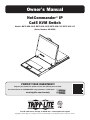
NetCommander® IP
Cat5 KVM Switch
Models: B070-008-19-IP, B070-016-19-IP, B072-008-1-IP, B072-016-1-IP
(Series Number: AG-00C3)
PROTECT YOUR INVESTMENT!
Register your product for quicker service and ultimate peace of mind.
You could also win an ISOBAR6ULTRA surge protector—a $50 value!
www.tripplite.com/warranty
1111 W. 35th Street, Chicago, IL 60609 USA • www.tripplite.com/support
Copyright © 2014 Tripp Lite. All rights reserved. All trademarks are the property of their respective owners.
1
Table of Contents
Legal Notice . . . . . . . . . . . . . . . . . . . . . . . . . . . 3
3. Conducting a Remote Session . . . . . . . . . . . 36
1. Product Overview . . . . . . . . . . . . . . . . . . . . . 3
3.1 Starting a Remote Session . . . . . . . . . . . . . . . . . . . . 36
3.2 Remote Session Toolbar . . . . . . . . . . . . . . . . . . . . . . 37
1.1 Features and Benefits . . . . . . . . . . . . . . . . . . . . . . . 3
3.2.1 Pin Toolbar . . . . . . . . . . . . . . . . . . . . . . . . . . . . . . . . . . 37
1.2 Terminology . . . . . . . . . . . . . . . . . . . . . . . . . . . . . . . . 4
3.2.2 Session . . . . . . . . . . . . . . . . . . . . . . . . . . . . . . . . . . . . 37
1.3 Target Server Compatibility . . . . . . . . . . . . . . . . . . . 4
3.2.3 Video . . . . . . . . . . . . . . . . . . . . . . . . . . . . . . . . . . . . . 39
1.4 Client Computer Compatibility . . . . . . . . . . . . . . . . . 4
3.2.4 Power . . . . . . . . . . . . . . . . . . . . . . . . . . . . . . . . . . . . . 40
1.5 Safety . . . . . . . . . . . . . . . . . . . . . . . . . . . . . . . . . . . . 4
3.2.5 Keys . . . . . . . . . . . . . . . . . . . . . . . . . . . . . . . . . . . . . . 41
1.6 System Components . . . . . . . . . . . . . . . . . . . . . . . . . 5
3.2.6 Mouse . . . . . . . . . . . . . . . . . . . . . . . . . . . . . . . . . . . . . 43
1.7 The NetCommander IP Unit . . . . . . . . . . . . . . . . . . . . 6
3.2.7 Server/Serial . . . . . . . . . . . . . . . . . . . . . . . . . . . . . . . . 46
1.8 Rackmounting the NetCommander IP . . . . . . . . . . . . 8
3.2.8 Full Screen . . . . . . . . . . . . . . . . . . . . . . . . . . . . . . . . . 46
1.8.1 Standard Console KVM Switch Instructions . . . . . . . . . . . 8
3.2.9 Logout . . . . . . . . . . . . . . . . . . . . . . . . . . . . . . . . . . . . . 46
1.8.2 2-Post Rack Console KVM Switch Instructions . . . . . . . . . 8
3.3 Shared Session . . . . . . . . . . . . . . . . . . . . . . . . . . . . . 46
1.9 Connecting the System . . . . . . . . . . . . . . . . . . . . . . . 9
3.4 Exclusive Session . . . . . . . . . . . . . . . . . . . . . . . . . . . 46
1.10 Initial Settings (Default IP Address) . . . . . . . . . . . . 9
4. Local Console . . . . . . . . . . . . . . . . . . . . . . . . 47
2. Web Configuration Interface . . . . . . . . . . . . . 13
4.1 Move Label (F1) . . . . . . . . . . . . . . . . . . . . . . . . . . . . 47
2.1 Logging Into the Web Configuration Interface . . . . . 13
4.2 Tuning (F5) . . . . . . . . . . . . . . . . . . . . . . . . . . . . . . . . 47
2.2 Web Configuration Interface Layout . . . . . . . . . . . . . 14
4.3 Power Management . . . . . . . . . . . . . . . . . . . . . . . . . 48
2.3 My Targets Section . . . . . . . . . . . . . . . . . . . . . . . . . . 15
4.4 (F2) Setting . . . . . . . . . . . . . . . . . . . . . . . . . . . . . . . . 48
2.4 Configuration Section . . . . . . . . . . . . . . . . . . . . . . . . 16
2.4.1 Firmware Upgrade . . . . . . . . . . . . . . . . . . . . . . . . . . . . . 17
2.4.2 Backup/Restore . . . . . . . . . . . . . . . . . . . . . . . . . . . . . . 19
2.4.3 SSL Certificate . . . . . . . . . . . . . . . . . . . . . . . . . . . . . . . 20
2.4.4 Device . . . . . . . . . . . . . . . . . . . . . . . . . . . . . . . . . . . . . 21
2.4.5 Users . . . . . . . . . . . . . . . . . . . . . . . . . . . . . . . . . . . . . 22
2.4.6 Switch Configuration . . . . . . . . . . . . . . . . . . . . . . . . . . . 24
2.4.7 User Targets . . . . . . . . . . . . . . . . . . . . . . . . . . . . . . . . . 25
2.4.8 Power Devices . . . . . . . . . . . . . . . . . . . . . . . . . . . . . . . 25
2.4.9 Power Outlets . . . . . . . . . . . . . . . . . . . . . . . . . . . . . . . . 27
2.4.10 Serial Ports . . . . . . . . . . . . . . . . . . . . . . . . . . . . . . . . 28
2.4.11 Security . . . . . . . . . . . . . . . . . . . . . . . . . . . . . . . . . . . 28
2.4.12 Authentication . . . . . . . . . . . . . . . . . . . . . . . . . . . . . . 30
2.4.13 Date & Time . . . . . . . . . . . . . . . . . . . . . . . . . . . . . . . . 34
2.5 Password Section . . . . . . . . . . . . . . . . . . . . . . . . . . . 34
2.6 Events Section . . . . . . . . . . . . . . . . . . . . . . . . . . . . . 35
5. Serial Port Pinout . . . . . . . . . . . . . . . . . . . . . 51
6. Security Certificate Installation . . . . . . . . . . 51
7. Technical Specifications . . . . . . . . . . . . . . . . 57
8. Video Resolution and Refresh Rates . . . . . . 58
9. Warranty & Product Registration . . . . . . . . . 58
2
Legal Notice
This manual and the software described in it are furnished under license, and may be used or copied only in accordance with the terms
of such license. The content of this manual is provided for informational use only, and is subject to change without notice. It should not in
and of itself be construed as a commitment by Tripp Lite, which assumes no responsibility of liability for any errors or inaccuracies that may
appear in this book.
The software that accompanies this manual is licensed for use by the Licensee only, in strict accordance with the software license
agreement, which the Licensee should read carefully before commencing use of the software. Except as permitted by the license, no part
of this publication may be reproduced, stored in retrieval system, or transmitted in any form or by any means, electronic, mechanical,
recording, or otherwise, without the prior written permission of Tripp Lite.
1. Product Overview
1.1 Features and Benefits
• Directly connect up to 16 (B070-016-19-IP or B072-016-1-IP) or 8 (B070-008-19-IP or B072-008-1-IP) computers/servers.
• Up to 2 users (1 local, 1 remote) can simultaneously access the KVM
• Up to 5 users can share a single remote session
• Multi-level account access: Administrator and User account types.
• Remote authentication support; RADIUS and LDAP/S
• Supports both IPv4 and IPv6
• PDU Control - Add IP PDUs as devices that can be controlled by the KVM. Assign individual ports on the KVM to a PDU port to power cycle
or power off/on the computer/server connected to that port.
• BIOS level control to any server’s brand and model, regardless of the server condition and network connectivity. Covers the entire spectrum
of crash scenarios.
• Compatible with Windows and Linux operating systems.
• Connect computer/servers up to 100 ft. (30 m.) away from the KVM using inexpensive Cat5e/6* cabling and B078-101-USB2,
B078-101-USB-1 and B078-101-PS2 SIUs
• Java-based application allows control of a target server via web browser from any location over a secured IP connection.
• Features two 10/100 Mbps LAN ports, so that if one fails, the other takes over.
• Supports the highest security standards for encryption (128-bit AES and HTTPS).
• Virtual Media allows an .iso file located in a Shared folder of a SAMBA or NFS server to be mounted to a Target Server and accessed as if
it were directly stored on it.
• Supports Virtual Media data transfer rates up to 12Mbps (B078-101-USB2 required). A B078-101-USB-1 can be used to provide Virtual
Media support, but only at speeds up to 1Mbps.
• Event log records events that take place on the installation, such as logins, reboots, network settings changes, etc..
• Features two RJ45 serial ports for connecting serial manageable devices, such as PDUs, firewalls, and routers.
• Allows for system sent messages to SNMP server to notify of LAN failures.
• Allows for the installation of a SSL certificate to ensure secure transactions between the Web servers and browsers.
• Graphical OSD and toolbars provide convenient, user-friendly remote operation.
• Text based OSD provides convenient, user-friendly local operation.
• Supports video resolutions up to 1920 x 1080 @ 60Hz. (B070-console KVMs are limited to video resolutions up to 1366 x 768 at the
local console.)
• Flash upgradeable firmware over the network.
* To ensure proper functionality, shielded Cat5e/6 cable must be used with the B078-101-USB2, and is recommended for all other SIUs for best performance.
3
1. Product Overview
1.2 Terminology
The following table describes terms used in this guide.
Term
Definition
Target Server
The computer/server that is connected directly to the KVM, and which is accessed via the local console or by a
Client Computer running a remote session.
Client Computer
A computer running a remote session, which is used to access computer/servers or devices connected to the KVM.
Remote Session
The process of remotely accessing the KVM via Client Computer, and controlling Target Servers and other
connected devices.
RICCs/ROCs/SIUs
RICC, ROC, and SIU refer to the dongles that are used to connect the KVM switch to a computer/server via Cat5e/6
cable. RICCs are the earliest versions of these dongles, and stand for Remote Interface Connection Cable. ROCs
are the second generation of these dongles, and stand for RICC on Cable. SIUs are the current versions of these
dongles, and stand for Server Interface Units. Functionally, they all serve the same purpose. The B078-101-PS2,
B078-101-USB-1, and B078-101-USB2 are the SIUs that will be used with the NetCommander UP KVM Switches.
1.3 Target Server Compatibility
• PS/2 and USB computers/servers
• Computer/servers with a HD15 (VGA) port
• Computer/servers running Windows or Linux operating systems
1.4 Client Computer Compatibility
• Pentium 4 with 2 GB memory
• Supports Windows and Linux operating systems.
• Windows operating systems can use Internet Explorer, Firefox, or Chrome browsers.
• Linux operating systems can use Firefox or Chrome browsers.
1.5 Safety
• Read all of these instructions. Save them for future reference.
• Follow all warnings and instructions marked on the device.
• Use of this equipment in life support applications where failure of this equipment can reasonably be expected to cause the failure of the
life support equipment or to significantly affect its safety or effectiveness is not recommended. Do not use this equipment in the presence
of a flammable anesthetic mixture with air, oxygen or nitrous oxide.
• This device is designed for IT power distribution systems with up to 230V phase-to-neutral voltage.
• Do not place the device on any unstable surface (cart, stand, table, etc.). If the device falls, serious damage will result.
• Do not use the device near water.
• Do not place the device near, or over, radiators or heat registers.
• The device cabinet is provided with slots and openings to permit adequate ventilation. To ensure reliable operation and protect against
overheating, these openings must never be blocked or covered.
• The device should not be placed on a soft surface (bed, sofa, rug, etc.), as this will block its ventilation openings. Likewise, the device
should not be placed in a built-in enclosure unless adequate ventilation has been provided.
• Never spill liquid of any kind on the device.
• Unplug the device from the wall outlet before cleaning. Use a damp cloth for cleaning. Do not use liquid or aerosol cleaners.
• The device should be operated from the type of power source indicated on the marking label. If you are not sure of the type of power
available, consult your dealer or local power company.
• To prevent damage to your installation, ensure that all devices are properly grounded.
• The device is equipped with a 3-wire grounding type plug. This is a safety feature. If you are unable to insert the plug into the outlet,
contact your electrician to replace your obsolete outlet. Do not attempt to defeat the purpose of the grounding-type plug. Always follow
your local/national wiring codes.
• Position system cables and power cables carefully to ensure that nothing rests on any cable. Route the power cord and cables so that
they cannot be stepped on or tripped over.
4
1. Product Overview
• If an extension cord is used with this device, make sure that the total ampere rating of all products used on the cord does not exceed the
extension cord ampere rating. Make sure that the total of all products plugged into the wall outlet does not exceed 15 amperes.
• To help protect your system from sudden transient increases and decreases in electrical power, it is recommended that you plug your
devices into a Tripp Lite surge suppressor, line conditioner, or uninterruptible power supply (UPS).
• When connecting or disconnecting power to hot-pluggable power supplies, observe the following precautions:
o Install the power supply before connecting the power cable to the power supply
o Unplug the power cable before removing the power supply
o If the system has multiple sources of power, disconnect power from the system by unplugging all power cables from the power supplies
o Never push objects of any kind into or through cabinet slots. They may touch dangerous voltage points or short out parts, resulting in a
risk of fire or electrical shock
o Do not attempt to service the device yourself. Refer all servicing to qualified service personnel
• If the following conditions occur, unplug the device from the wall outlet and bring it to qualified service personnel for repair:
o The power cord or plug has become damaged or frayed
o Liquid has been spilled into the device
o The device has been exposed to rain or water
o The device has been dropped or the cabinet has been damaged
o The device exhibits a distinct change in performance, indicating a need for service
o The device does not operate normally when the operating instructions are followed
• Adjust only those controls that are covered in the operating instructions. Improper adjustment of other controls may result in damage that
will require extensive repair work by a qualified technician.
1.6 System Components
Before installing the NetCommander IP, verify that you have all the components on the following list, as well as any other items required for
installation.
• B070-008-19-IP, B070-016-19-IP, B072-008-1-IP or B072-016-1-IP NetCommander IP KVM
• A B078-101-PS2, B078-101-USB-1 or B078-101-USB2 (ordered separately) for each computer/server you will be connecting.
• Cat5e/6* cable (ordered separately) for each computer/server you will be connecting, as well as for network and serial connections.
• Rackmount hardware (included).
• Power cord (included).
* To ensure proper functionality, shielded Cat5e/6 cable must be used with the B078-101-USB2, and is recommended for all other SIUs for best performance.
5
1. Product Overview
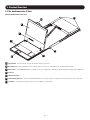
1.7 The NetCommander IP Unit
Console KVM Switch Front View
6
1
2
3
4
6
5
7
1 Upper Handle – Pull to slide the console out; push to slide the console in.
2 19” LCD Screen – After sliding the console out, flip up the cover to access the LCD screen, keyboard and touchpad.
3 LCD Controls – The LCD On/Off button is located here, as well as buttons to control the position and picture settings of the LCD screen.
4 Keyboard
5 2-Button Touchpad
6 Rackmounting Brackets – There are rackmount brackets to secure the chassis to a system rack located at each corner of the unit.
7 Lock LEDs – The Num Lock, Caps Lock, and Scroll Lock LEDs are located here.
6
1. Product Overview
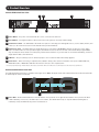
Console KVM Switch Rear View
4
6
RESET
3
1
2
5
1 Power Outlet – The power cord included with the console connects to the unit here.
2 Reset Button – Pressing this button for 10 seconds restores the system to its factory default settings.
3 Serial Ports 1 and 2 – The KVM features two RJ45 serial ports for connecting serial manageable devices, such as PDUs, firewalls, and
routers (see the Serial Pinout section in this manual for the pinout information).
4 LAN Ports 1 and 2 – The KVM features two RJ45 LAN ports for connecting to 10/100 Mbps networks. If LAN 1 goes down, LAN 2
takes over. When LAN 1 becomes operational again, the KVM will need to be rebooted to make it the default LAN port again. Note:
Only one LAN port can be turned on at a time; they cannot both be turned on. If you don’t wish to use network redundancy, connect a
single network cable to the LAN 2 Port.
5 USB Port – This port currently serves no functional purpose. It is included for future functionality upgrades.
6 Server Ports – When connecting a computer/server, Cat5e/6* cabling connects from an available server port to a B078-101-PS2,
B078-101-USB-1 or B078-101-USB2 SIU which in turn connects to the computer/server.
* To ensure proper functionality, shielded Cat5e/6 cable must be used with the B078-101-USB2, and is recommended for all other SIUs for best performance.
Rackmount KVM Switch Front View
The NetCommander IP front panel is illustrated in the figure below. Note: The figure below shows a B072-016-1-IP, but the front panel will
be functionally the same for all models.
116
MODEL: B072 - 016 - 1- IP
1
1 Power LED – This Blue LED illuminates to indicate that the unit is powered on. No light indicates that the unit is powered off. When
a LAN redundancy event occurs, and LAN 2 takes over for LAN 1, this LED will blink slowly. To stop the LED from blinking after a
redundancy event, the KVM must be powered off and back on.
7
1. Product Overview
Rackmount KVM Switch Rear View
The NetCommander IP back panel is illustrated in the figure below. Note: The figure below shows the back panel for a B072-016-1-IP,
but the back panel will be functionally the same for all models, with the only difference being the number of server ports.
3
1
2
4
7
6
5
1 Power Outlet – The power cord included with the KVM connects to the unit here.
2 Reset button – Pressing this button for 10 seconds restores the system to its factory default settings.
3 Serial Ports 1 and 2 – The KVM features two RJ45 serial ports, for connecting serial manageable devices, such as PDUs, firewalls, and
routers. (see the Serial Pinout section in this manual for the pinout information)
4 LAN Ports 1 and 2 – The KVM features two RJ45 LAN ports for connecting to 10/100 Mbps networks. If LAN 1 goes down, LAN 2
takes over. When LAN 1 becomes operational again, the KVM will need to be rebooted to make it the default LAN port again. Note:
Only one LAN port can be turned on at a time; they cannot both be turned on. If you don’t wish to use network redundancy, connect a
single network cable to LAN 2 Port.
5 Console KVM ports – A USB keyboard and mouse, and VGA (HD15) monitor connect here for local operation of the NetCommander IP KVM.
6 USB Port – This port currently serves no functional purpose. It is included for future functionality upgrades.
7 Server ports – When connecting a computer/server, Cat5e/6* cabling connects from an available server port to a
B078-101-PS2, B078-101-USB-1 or B078-101-USB2 SIU which in turn connects to the computer/server.
* To ensure proper functionality, shielded Cat5e/6 cable must be used with the B078-101-USB2, and is recommended for all other SIUs for best performance.
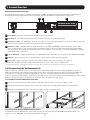
1.8 Rackmounting the NetCommander IP
Follow all instructions in the safety section of this manual before rackmounting. Make sure to write down the MAC Address and Device
Number from the bottom of the unit before rackmounting, as they will be useful when finding the IP address assigned by the DHCP server.
For the B072-Series, attach the included mounting brackets to the sides of the KVM switch (either front or rear, depending on user
preference) using the included hardware, and then mount the KVM into your rack using user supplied screws. The B070-Series Console KVM
Switches come with removable rackmount brackets, allowing the unit to be installed by a single person.
1.8.1 Standard Console KVM Switch Instructions
1 Remove the rackmount brackets from the unit and mount them to the back of the rack using user-supplied screws.
2 Take the Console KVM switch and gently slide it into the rack so that it inserts into the rackmount brackets you just mounted.
3 Mount the rackmount brackets on the front of the unit to the rack using user-supplied screws.
1
2-3
1.8.2 2-Post Rack Console KVM Switch Instructions
The B070-Series Console KVM Switches can be mounted to a 2-Post Rack using Tripp Lite’s B019-000 2-Post Rackmount Kit (sold
separately). See the B019-000 owner’s manual for installation instructions.
8
1. Product Overview
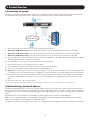
1.9 Connecting the System
The figure below illustrates the NetCommander IP system overview. Note: The figure below shows a B072-016-1-IP. The only difference in
set up between models is the number of ports, and the lack of an external console on the B070-Series console KVMs.
1. Make sure that power to all the devices you will be connecting has been turned off.
2. (B072-Series KVM Switches Only) Connect a VGA cable from the monitor to the HD15 (VGA) port on the back of the KVM.
3. (B072-Series KVM Switches Only) Connect the keyboard’s USB connector to the USB Keyboard port on the back of the KVM.
4. (B072-Series KVM Switches Only) Connect the mouse’s USB connector to the USB Mouse port on the back of the KVM.
5. Connect a Cat5e/6* cable from an available server port on the back of the KVM to a SIU (B078-101-PS2, B078-101-USB-1 or B078101-USB2) appropriate for the computer you are adding.
6. Connect the SIU’s connectors to the corresponding ports on the computer/server.
7. Repeat steps 5 and 6 for each computer/server you are adding.
8. Connect a Cat5e/6 cable from your network to the LAN 1 port on the back of the KVM.
9. Connect a second Cat5e/6 cable from your network into the KVM’s LAN 2 port.
10. Optional: Connect up to two serial devices to the RJ45 Serial Ports 1 and 2 on the back of the KVM switch (See the Configuring Serial
Port Settings section of this manual for details on configuration. See the Serial Pinout section in this manual for the pinout information).
11. Connect the included power cord between the C14 outlet on the back of the unit and a Tripp Lite Surge Suppressor, Power Distribution
Unit (PDU), or Uninterruptible Power Supply (UPS). There is no Power On/Off switch, so plugging in the power cord will power on the
KVM.
12. Turn on the power to all of the connected devices.
* To ensure proper functionality, shielded Cat5e/6 cable must be used with the B078-101-USB2, and is recommended for all other SIUs for best performance.
1.10 Initial Settings (Default IP Address)
By default, the NetCommander IP is set to have the network’s DHCP server pull an IPv4 address for it. Referencing the unit’s Mac address,
which can be found on the bottom panel of the KVM, have your network administrator provide you with the IP address that was assigned by
the DHCP server. You can also obtain the IP address by logging into the KVM’s OSD via the local console, and navigating to the F2 Settings
menu.
On networks that do not have a DHCP server, the KVM boots with the default static IPv4 address of 192.168.0.254.
Note: There is no default IPv6 address for the KVM switch. An IPv6 address can be automatically assigned via DHCP server, a Stateless
address can be assigned, or a static address can be manually entered.
To configure an IP address for the KVM, you can use the local console OSD or the Web Configuration Interface. Both methods are described
9
1. Product Overview
in the following sections.
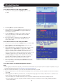
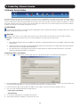
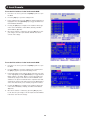
To set the IPv4 address via the local console OSD:
1. From the local console, press the left [Shift] key twice to open
the OSD.
2. Press the [F2] key to open the Settings menu.
3. In the Settings menu, press the [Tab] key until the DHCP field is
highlighted. Press the [Spacebar] key to toggle the DHCP field
from Enabled to Disabled.
4. Pressing the [Tab] key to navigate to the additional fields, type
in the desired IP Address, Subnet Mask, Gateway and DNS
Server Address (optional).
5. Once the IP address is satisfactory, press the [Esc] key to save
your changes. This will require that the KVM be rebooted to
save the new settings.
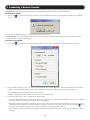
To set the IPv6 address via the local console OSD:
1. From the local console, press the left [Shift] key twice to open the OSD.
2. Press the [F2] key to open the Settings menu, and then press the
[F2] key again to open the IPv6 Settings menu.
3.
In the IPv6 Settings menu, with the Mode field at the top of the screen
highlighted, press the [Spacebar] key to toggle between DHCP, Stateless, and Static. DHCP is selected by default, and automatically
assigns an IP address via the IPv6 DHCP server. Stateless is an option for networks with a compliant router that performs Stateless IPv6 configuration. Static allows you to manually assign an IP address.
4. Pressing the [Tab] key to navigate to the additional fields, type in the
desired IP Address, Gateway, and DNS Server Address (optional).
Note: DNS IP should be set to 0.0.0.0 to indicate no DNS.
5. Once the IP address is satisfactory, press the [Esc] key twice to exit
and save your changes. This will require that the KVM be rebooted to
save the new settings.
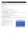
To set the IP address via the Web Configuration Interface:
Note:
• Before logging on the first time, verify that you have the latest Java installed on your computer (Java 1.6 or higher is required). If not, you
can download and install Java from http://www.java.com/en/download/index.jsp.
• Only SSL connections are allowed, so you must start the IP address with HTTPS, not HTTP.
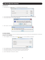
1. Open your web browser (see the Client Computer Compatibility section of this manual for browser support) and enter in the IP address
of the KVM.
2. When logging into the KVM from your web browser, a Security Alert message appears to inform you that the device’s certificate is not
trusted, and asks if you want to proceed. You have two options:
• If you are working on a computer other than your own, accept the certificate for just this session by clicking to proceed.
• If you are working at your own computer, install the certificate. Reference the instructions in the Security Certificate Installation
section of this manual.
10
1. Product Overview
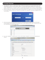
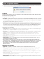
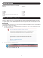
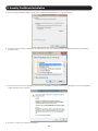
3. Upon installing the certificate or accepting the unrecognized certificate for the current session, the initial web page appears, and the
Java application is launched. Before the installation completes, a security warning may appear stating that the connection to this
website is untrustworthy. This is a security issue similar to one you get from your web browser. You can choose to continue anyway, or
install the certificate in the Java control panel. Refer to the Security Certificate Installation section of this manual for further instructions.
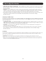
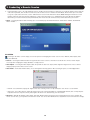
4. After the Java application is launched, the login page appears. If the login page does not appear on its own, click the Log On button in
the center of the web page to bring it up. If clicking on the Log On button does not bring up the login page, add /targets.jnlp to the end
of your IP address.
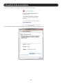
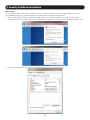
5. Enter in your username and password, and press Enter. If this is the first time you are accessing the KVM, enter in the default
username (admin) and password (access). The My Targets page of the Web Configuration Interface opens, showing the state of your
unit, and displaying all your available Target Servers.
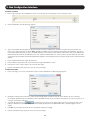
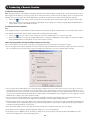
6. Click on the Configuration icon at the top of the screen to pull up the KVM’s Configuration screen. It opens with the Device tab
displayed.
11
1. Product Overview
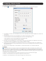
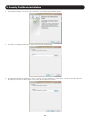
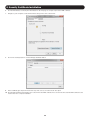
7. There are two LAN sections in the Device tab, one for IPv4 and one for IPv6. For IPv4, you have the options of automatically assigning an address via DHCP server (default) and manually assigning an address. For IPv6, you have the options of automatically assigning an
address via DHCP server (default), automatically assigning a stateless address, manually assigning an address, or disabling IPv6 altogether. Make the desired selections, depending on how you wish the IP address to be assigned.
8. Populate the fields in the IPv4 or IPv6 sections with the desired network information.
9. Click the Save icon in the toolbar above the Configuration menu tabs to save the network settings. Upon clicking Save, you will be prompted to reboot the KVM to finish the implementation of the new Device settings. Click Yes to proceed.
12
2. Web Configuration Interface
The NetCommander IP can be accessed in two ways: locally via the local console OSD, or remotely via the Web Configuration Interface.
This section of the manual details the Web Configuration Interface, which can be used to access the computer/servers and other devices
connected to the KVM, as well as to configure the KVM’s settings and accounts.
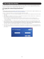
2.1 Logging Into the Web Configuration Interface
Note:
• Before logging on the first time, verify that you have the latest Java installed on your computer (Java 1.6 or higher is required). If not, you
can download and install Java from http://www.java.com/en/download/index.jsp.
• Only SSL connections are allowed, so you must start the IP address with HTTPS, not HTTP.
1. Open your web browser (see the Client Computer Compatibility section of this manual for browser support) and enter in the IP address
of the KVM.
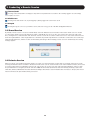
2. When logging into the KVM from your web browser, a Security Alert message appears to inform you that the device’s certificate is not
trusted, and asks if you want to proceed. You have two options:
• If you are working on a computer other than your own, accept the certificate for just this session by clicking to proceed.
• If you are working at your own computer, install the certificate. Reference the instructions in the Security Certificate Installation
section of this manual.
3. Upon installing the certificate or accepting the unrecognized certificate for the current session, the Java application begins to install.
Before the installation completes, a security warning may appear stating that the connection to this website is untrustworthy. This is
a security issue similar to one you get from your web browser. You can choose to continue anyway, or install the certificate in the Java
control panel. Refer to the Security Certificate Installation section of this manual for further instructions.
4. After installation has completed, the login page appears. If the login page does not appear on its own, click the Log On button in the
center of the web page to bring it up. If clicking on the Log On button does not bring up the login page, add /targets.jnlp to the end of
your IP address.
13
2. Web Configuration Interface
5. Enter in your username and password, and press Enter. If this is the first time you are accessing the KVM, enter in the default
username (admin) and password (access). The My Targets page of the Web Configuration Interface opens, showing the state of your
unit, and displaying all your available Target Servers.
2.2 Web Configuration Interface Layout
The Web Configuration Interface contains the following main elements:
1
2
3
4
Element
1
Header Bar
Description
The Header Bar is at the very top of the screen, and displays the following:
XA general Window Icon, which you can double-click on to close the Web Configuration Interface screen, or
click once on to open a menu with options for restoring, moving, sizing, minimizing, maximizing, or closing
the screen.
To the right of the general Window Icon is displayed the product description and IP address.
The right-hand side includes the standard browser buttons for minimizing, maximizing, and closing the screen.
2
Menu Bar
The Menu Bar is directly below the Header Bar, and includes icons that allow you to navigate between the
various sections of the Web Configuration Interface, as well as to display Web Configuration Interface screens in a
Cascaded format, Log Out, and display information about the KVM.
The My Targets icon brings you to the page that displays the Target Servers and Serial Devices that
you can access.
The Configuration icon brings you to the page that allows you to configure the KVM’s settings and
account access.
The Password icon brings you to a page that allows the logged in account to change their password.
The Events icon brings you to the page where all of the events that take place on the installation are
logged.
The Cascade icon displays the sections of the Web Configuration Interface as cascaded pages.
The Maximize icon brings the Web Configuration Interface out of Cascade mode, displaying it as a
maximized screen.
The Log Out icon closes the Web Configuration Interface screen, and pulls up the Login Screen.
The About icon pulls up a screen that gives you the GUI Client Version and Firmware Version of the
KVM.
3
Toolbar
The Toolbar displays icons that allow you to perform actions available to the section selected via the Menu Bar
4
Data Pane
The Data Pane displays information that corresponds to the Menu Bar section that you selected.
14
2. Web Configuration Interface
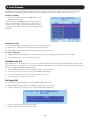
2.3 My Targets Section
The My Targets section of the Web Configuration
Interface is the first page that is displayed upon
logging into the KVM remotely. This section is
where users remotely access the connected
computers/servers and serial devices. When
accessing the My Targets section, only the
connected computers/servers and devices that the
logged-in account has access to are displayed in
the Data Pane. For administrators, a graphic of
the KVM’s back panel is displayed in between the
Toolbar and Data Pane. The features of this page
are described in the following section.
The following table describes the icons found in the My Targets section Toolbar.
Icon
Description
In the My Targets section, clicking the Reload icon refreshes the page to display the most current information.
Clicking the Power icon brings up a dropdown menu of power management actions you can perform on the selected port.
Note: In order to perform power management actions on a port, it must be configured to match a power outlet of a power
device that has been added to the KVM. (See the Power Device and Power Outlets sections of this manual for details)
Cycle – Choose the Cycle option to perform a power cycle on the computer/server connected to the selected port.
Up –Choose the Up option to turn the power to the computer/server connected to the selected port on.
Down – Choose the Down option to turn the power to the computer/server connected to the selected port off.
The Disconnect icon allows admin accounts to disconnect users from a server port. If a server port is being accessed by
another account, highlighting the port and clicking the Disconnect icon terminates the remote session, making the Target
Server available for access.
Clicking on the Display icon initiates a remote session, with the selected port displayed. (See the Remote Session section
of this manual for details on managing a remote session)
For administrators, a graphic of the KVM’s back panel is displayed in between the Toolbar and Data Pane. The features of this graphic are
described below.
• Power Outlet – A Green power outlet indicates that it is working. A Red power outlet indicates that it is not working properly. A Black
power outlet indicates that it is not connected.
• Serial 1 and 2 Ports – An Orange serial port indicates that a serial device is connected and currently being accessed by another account.
A Black serial port indicates one of three things; a device is connected and available for use, a device is connected but is not functioning
properly, or a device is not connected.
• LAN 1 and 2 Ports – A Green LAN port indicates that it is the active LAN port. The other LAN port will be Black. Only one LAN can be
operational at a time. When a LAN redundancy event occurs, and LAN 2 takes over for LAN 1, the LAN 1 port will be red and LAN 2 port
will be green.
• Target Servers – The Target Server ports will illuminate different colors to indicate their status. The different statuses are discussed in
detail in the chart on the following page. A Blue port indicates that the Target Server is Available; a Green port indicates that a Remote
Session or Local Exclusive Session is taking place on the Target Server; an Orange port indicates a Remote Exclusive Session; a Reddish
Brown port indicates a Blocked server status; a Black port indicates an Off server status; a Red port indicates a No Communication with
Device server status.
•
, - The arrow icons to the lower-left of the back panel graphic allow the logged in account to hide or unhide it. Clicking the
will hide the rear panel graphic; clicking the arrow will unhide it.
15
arrow
2. Web Configuration Interface
The following table describes the columns found in the My Targets section Data Pane.
Server Name
The Server Name column displays all of the Target Servers and Serial devices that are accessible to the logged in
account. The Server Name for each port can be changed in the Configuration section of the Web Configuration
Interface (see the Switch Configuration section of this manual for details). Double-click on a Target Server to initiate a
remote session (See the Remote Session section of this manual for details on managing a remote session).
Server Status
The Server Status column shows the status of the Target Server connected to the corresponding port: Available, Off,
Blocked, Local Exclusive Session, Remote Exclusive Session, Remote Session, or No Communications with Device.
• Available – Indicates that a computer is connected to the corresponding port, and is available for use. This server
status is indicated by a Blue port in the graphic of the KVM’s back panel.
• Off – Indicates that a computer/server is not connected to the corresponding port. This server status is indicated by
a Black port in the graphic of the KVM’s back panel.
• Blocked – Indicates that the maximum number of simultaneous users have logged onto the KVM and are accessing
connected computers. In this situation, the status of all Target Servers is Blocked, except those that are being
accessed by other accounts. For those ports that are being accessed by other accounts, the status will appear as
either Remote Session or Remote Exclusive Session. (see the Sharing a Remote Session and Exclusive Session
sections in this manual for details) Target Servers that are Blocked cannot be accessed. A Blocked server status is
indicated by a Reddish Brown port in the graphic of the KVM’s back panel.
• Local Exclusive Session – Indicates that the corresponding port is currently being accessed by a local account.
This server status is indicated by a Green port in the graphic of the KVM’s back panel.
• Remote Exclusive Session – Indicates that an account is currently accessing the corresponding port in exclusive
mode, preventing anyone else from connecting to it. This server status is indicated by an Orange port in the graphic
of the KVM’s back panel.
• Remote Session – Indicates that an account is currently accessing the corresponding port in share mode, which allows
up to 5 users to access a port at the same time. (see the Sharing a Remote Session and Exclusive Session sections in
this manual for details) This server status is indicated by a Green port in the graphic of the KVM’s back panel.
• No Communications with Device – Indicates that a computer/server is connected to the corresponding port, but is
not communicating with the KVM, and is therefore inaccessible. This server status is indicated by a Red port in the
graphic of the KVM’s back panel.
User
The User column displays the account that is currently accessing the corresponding port.
There is an untitled column to the right of the User column. This column will contain a colored icon that indicates which
type of SIU is connected. Green indicates that a B078-101-USB2 is connected; Light Blue indicates that a B078-101USB-1 is connected; Orange indicates that a 0SU51078, 0SU51079, B078-101-PS2, or B078-101-USB is connected.
SIU (Server
Interface Unit)
This column includes a description of the connected SIU. The B078-101-USB2 is described as a FVM SIU, the B078101-USB-1 as a VM SIU, and the 0SU51078, 0SU51079, B078-101-PS2, and B078-101-USB as a SIU.
2.4 Configuration Section
The Configuration section of the Web Configuration Interface is
where administrator accounts can configure the KVM’s settings and
account access. When accessing the Configuration section, there
are a number of sub-sections displayed as notebook tabs. Clicking
on a tab will display the settings for that sub-section. The features of
the Configuration section are described in the following pages.
The following table describes the functionality of the Web configuration toolbar buttons.
Icon
Description
Click the Save icon after making any changes in the Configuration section. This saves your changes.
In the Configuration section, clicking the Reload icon will return a page to the most recently saved settings. For example,
if you enter incorrect information into a field and want to go back to the previous value, but can’t remember what the
previous value of the field was, clicking the Reload icon will bring it back.
Click the Device Reboot icon to reboot the KVM.
Click the Device Upgrade to perform a firmware upgrade on the KVM (See the Firmware Upgrade section in this manual
for details).
Click the SIU Upgrade icon to perform a firmware upgrade on the SIUs in the installation (See the Firmware Upgrade
section in this manual for details).
16
2. Web Configuration Interface
Clicking on the Factory Restore icon will restore the KVM’s default settings, resetting all information that had been
changed. The affected settings include network information, servers, switches, users, and passwords. You will be given
the option of preserving the network settings when performing a Factory Restore.
Clicking on the Backup/Restore icon allows an administrator to backup or restore the KVM’s settings (See the Backup/
Restore section in this manual for details).
Clicking on the SSL Certificate icon allows an administrator to install an SSL certificate (See the SSL Certificate section in
this manual for details).
2.4.1 Firmware Upgrade
To perform a firmware upgrade, follow these steps:
Note: Depending on the type of firmware upgrade, the following settings may be erased: User settings, KVM switch settings, mouse and
video adjustments, and RS232 settings. The network settings remain intact. For more information, refer to the firmware release notes.
1. Download the firmware upgrade file from www.tripplite.com/support.
2. Save the firmware upgrade file on the Client Computer.
3. Login to the Web Configuration Interface and navigate to the Configuration section. In the Configuration section’s toolbar, click on the
icon. The Device Firmware Upgrade page appears, displaying the current firmware version installed on the KVM.
4. In the Version to upgrade with field, browse to and select the firmware upgrade file that you just downloaded from the Tripp Lite website.
5. Verify that the firmware upgrade file is a newer version than what is currently installed on the KVM.
6. Click the Start Upgrade button to begin the firmware upgrade. A progress bar will display the progress of the upgrade. An upgrade can
take several minutes.
7. When the upgrade completes, click the OK button on the prompt that appears to close out of the Web Configuration Interface and
reboot the KVM. You will be taken back to the login page.
8. Click the Log On button to log back into the Web Configuration Interface.
17
2. Web Configuration Interface
In addition to the KVM firmware, you can upgrade the SIU firmware to take advantage of new features.
1. Download the firmware upgrade file from www.tripplite.com/support.
2. Save the firmware upgrade file on the Client Computer.
3. Login to the Web Configuration Interface and navigate to the Configuration section. In the Configuration section’s toolbar, click on the
icon. The SIU Upgrade page appears.
4. Select the checkboxes of the Target Servers ports that are connected to the SIU(s) that you want to upgrade. Click the Select All button
to select all ports at the same time.
5. Click the Show Versions button to display the current hardware and firmware versions of the SIUs connected to the selected ports.
6.In Upgrade File field, browse to and select the firmware upgrade file that you just downloaded from the Tripp Lite website.
7. Verify that the firmware upgrade file is a newer version than what is currently installed on the SIU(s).
8. Click the Start Upgrade button to begin the firmware upgrade.
9. A prompt appears when the upgrade is complete, and asks if you want to show the new firmware versions of the SIUs.
Note: A reboot of the KVM is not necessary when upgrading the SIU firmware.
18
2. Web Configuration Interface
2.4.2 Backup/Restore
Using the Backup/Restore function in the Configuration sections toolbar, you can back up all configuration data and restore it at a later date.
To back up data:
1. In the toolbar, click on
icon. The Backup/Restore Data page appears.
2. In the Backup to file field, click the Browse button to open up the Enter file name to backup to screen.
3. Navigate to the location on your computer where you want to save the backup file, and then give it an appropriate file name and click
the Open button. Backup files are saved in the .64b format.
4.The Backup/Restore Data screen reappears with the newly saved location and file name populating the Backup to file field. Click on the
Backup button.
5. Upon completion of the backup, click the Close button to close the Backup/Restore Data screen.
19
2. Web Configuration Interface
To restore data:
1. In the toolbar, click on
icon. The Backup/Restore Data page appears.
2. Click the Browse button next to the Restore data from file field, and then navigate to and select the KVM backup.
3. Click the Restore button to restore the KVM configuration.
4. When complete, click the OK button to exit the Web Configuration Interface and perform a KVM reboot.
2.4.3 SSL Certificate
You can install an SSL Certificate to ensure secure transactions between the web server resident on the NetCommander and client browsers.
To install an SSL Certificate:
1. In the Configuration sections toolbar, click on the
icon. The SSL Certificate screen appears.
2. In the Certificate file field, browse to locate and select the Cer file you want to install.
3. In the Private key file field, locate and select the private key file in Microsoft PEM format.
4. In the Key password field, type in the password required to upload the private key file.
5. Click the Install button to install the SSL certificate.
20
2. Web Configuration Interface
6. When the SSL certificate has been installed, a prompt appears to let you know the installation was successful, and that the KVM will be
rebooted. Click the OK button to exit the Web Configuration Interface and reboot the KVM.
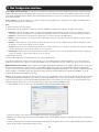
2.4.4 Device
The Device tab in the Configuration section allows administrators to configure the KVM’s Device ID, LAN, and SNMP settings. The settings in
this page are described in the following section.
Configuring the Device ID settings:
• Device Name – The Device Name field allows you to assign a name to the NetCommander IP. By default, the Device Name consists of the
letter ‘D’ followed by a 6-digit device number, which is printed on the label on the underside of the KVM. If the DHCP server is published
in the DNS server, you can connect to the NetCommander IP system using the device name, as follows: https://DeviceName. Simply type
in the desired Device Name and click the Save icon at the top of the page. Upon clicking Save, you will be prompted to reboot the KVM to
finish implementation of the new Device settings. Click Yes to proceed.
• TCP Port – The TCP Port refers to the port that the KVM’s session data is sent through and received. This field allows you to select a port
which the firewall or router security access list must enable inbound traffic through for the KVM’s IP address. For client computer access
from a secured LAN, the selected port should be open for communication. You can select any port from 800 to 65535. The default TCP
port is 900, and the default https port is 443. Simply type in the desired TCP Port and click the Save icon at the top of the page. Upon
clicking Save, you will be prompted to reboot the KVM to finish implementation of the new Device settings. Click Yes to proceed.
Configuring the IPv4 LAN Settings
• Enable DHCP – By default, the Enable DHCP checkbox is checked, allowing for an IP address to be automatically assigned by a DHCP server. To assign a fixed IP address of your own, uncheck this checkbox.
• MAC Address – The MAC Address field displays the KVM’s MAC address, which can be used when locating the IP address assigned to the KVM by a DHCP server. The MAC address is also located on the bottom panel of the KVM switch.
• IP Address – When the Enable DHCP checkbox is unchecked, this field becomes available for editing. Enter in an IP address appropriate for your network.
• Subnet Mask – When the Enable DHCP checkbox is unchecked, this field becomes available for editing. Enter in a Subnet Mask appropriate for your network.
• Default Gateway – When the Enable DHCP checkbox is unchecked, this field becomes available for editing. Enter in a Default Gateway appropriate for your network.
• When in DHCP mode, check the checkbox next to DNS Server to manually assign an address. When the Enable DHCP checkbox is unchecked, a DNS Server must be manual assigned. Enter a DNS server address appropriate for your network.
• After making any changes to the KVM’s LAN settings, click on the Save button at the top of the screen to save them
Upon clicking Save, you will be prompted to reboot the KVM to finish implementation of the new Device settings.
Click Yes to proceed.
Configuring the IPv6 LAN Settings
• Enable IPv6 – By default, the Enable IPv6 checkbox is checked. To disable IPv6, uncheck this checkbox.
• Mode – By default, the DHCP check box is checked, allowing for an IP address to be automatically assigned by a DHCP
server. The Mode section also provides you the options of automatically assigning a Stateless address and manually assigning a Static address. Check the checkbox of the method you wish to use for IP address assignment.
• IPv6 Address – When the Static mode checkbox is checked, this field becomes available for editing. Enter in an IP address appropriate for your network.
• Subnet Prefix Length – When the Static mode checkbox is checked, this field becomes available for editing. Enter in a Subnet Prefix Length appropriate for your network.
• Default Gateway – When the Static mode checkbox is checked, this field becomes available for editing. Enter in a Default Gateway appropriate for your network.
21
2. Web Configuration Interface
• Obtain DNS Server Address Automatically – When the DHCP mode checkbox is checked, this checkbox is also checked. When the Stateless or Static mode checkboxes are checked, this checkbox is deactivated, and you must manually enter a DNS Server address.
• DNS Server – When in DHCP mode, check the checkbox next to DNS Server to manually assign its address. When the Stateless or Static mode checkboxes are checked, the Obtain DNS Server Address Automatically checkbox is deactivated, and you must manually enter a DNS Server address. Enter a DNS Server address appropriate for your network.
• After making any changes to the KVM’s LAN settings, click on the Save button at the top of the screen to save them. Upon clicking Save, you will be prompted to reboot the KVM to finish implementation of the new Device settings.
Click Yes to proceed.
Configuring the SNMP settings:
This section of the Device tab allows you to configure the KVM so that notifications can be sent to a SNMP server when a LAN
port fails. Upon receiving notification of the failure, LAN redundancy is enabled. Note: If both LANs fail, a message cannot be
sent to the SNMP server.
• Trap Recipient Address – The Trap Recipient Address section provides three types of addresses that you can enter for the SNMP server that you want traps to be sent to: IPv4, IPv6, and Host. Check the checkbox of the type of address you wish to enter, and then enter in the address that corresponds to your SNMP server.
• Community – In this field, type in the SNMP write community string to be used for authentication of messages sent between the KVM and the SNMP server.
• After making any changes to the KVM’s SNMP settings, click on the Save button at the top of the screen to save them. Upon clicking Save, you will be prompted to reboot the KVM to finish implementation of the new Device settings.
Click Yes to proceed.
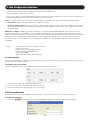
2.4.5 Users
The Users tab in the Configuration section allows administrators to Add, Edit, and Delete accounts on the KVM. Up to 256 accounts can be
added, with any combination of Administrators and Users. The following section describes this page, and how to configure accounts.
There are two levels of user access:
• Administrator – Has unrestricted access to all windows and settings, and can change the name and password of all users.
• User – Can access and control Target Servers that they are given access to by an administrator. Users cannot access the Configure or
Events sections of the Web Configuration Interface, nor can they disconnect remote sessions. When in a remote session, they are not
allowed to access the power management functionality.
22
2. Web Configuration Interface
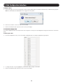
To add an account:
1. Click on the Users tab in the Configuration section. The Users page opens and displays a list of existing accounts.
2. Click the Add button. The Add User page appears.
3. Type in a User Name and Password. The password must be at least six alphanumeric characters long and cannot include the user
name, even if other characters are added. Note: Although User Names can be entered in both lowercase and uppercase, they are not
case sensitive when being used to login to the KVM; therefore, do not create two users with the same name. (e.g. user1, USER1) User
Name and Password must be 10 characters or less. The “special” characters &, <, >, and ” cannot be used for either the user name
or password. The User Name and Password parameters depend on the security level chosen (See the Security section in this manual for
details).
4. In the Confirm Password field, retype the password.
5. In the Permission dropdown menu, select the permission type: Administrator or User.
6.Click OK. The new account is added to the list in the Users page.
7. Click the Save button at the top of the screen to save your changes.
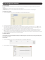
To edit an account:
1. In the Users page, select an account from the list and click the Edit button. The Edit User page appears.
2. Change the Permission and/or Access as required. Checking the Block checkbox next to the Access field blocks an account from
accessing the KVM, but keeps its information stored in the KVM. This way, if you ever want to reactivate the account, all you have to do
is go back in and uncheck this box.
3. To change the password, click
. The Password screen opens. In the upper textbox, type the new password; in the lower
textbox, confirm the new password. Note: You cannot change the password of an Administrator who is currently logged on to the
system.
4.Click OK. The Users page opens with the user information changed accordingly.
5. Click the Save button at the top of the screen to save your changes.
23
2. Web Configuration Interface
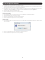
To delete a User:
1. In the Users page, select an account from the list and click the Delete button. The Delete Selected User(s) confirmation page appears.
Note: You cannot delete an Administrator who is logged onto the system.
2. Click Yes to delete the selected account(s) from the KVM.
3. Click the Save button at the top of the screen to save your changes.
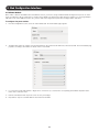
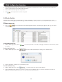
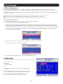
2.4.6 Switch Configuration
The Switch Configuration tab allows unique names to be assigned to each port, to help distinguish the Target Servers that are connected to
them.
To edit a port name:
1. From the Configuration section, click on the Switch Configuration tab. The Switch Configuration page appears.
2. To change the name of a port, highlight the current server name, and type a new name.
3. Click the Save button at the top of the screen to save your changes.
24
2. Web Configuration Interface
2.4.7 User Targets
By default, administrators are allowed access to all servers. However, you must define the access rights of each user account to the
following:
• Target Access – To initiate a remote session for the corresponding port.
• Virtual media access – To use the Virtual Media functionality when in a remote session for the corresponding port.
To configure User Targets:
1. From the Configuration section, select the User Targets tab. The User Targets page appears.
2. From the User dropdown menu, select an account to configure.
3. In the Target Access column, check the checkboxes of all ports that you are giving the account permission to access. Note: You can
click on the Unselect all Target Access button at the top of the column to clear the checkboxes of all ports. Correspondingly, you can
check the Select all Target Access button at the top of the column to check the checkboxes of all ports.
4. In the Virtual Media Access column, check the checkboxes of all ports that you are giving the account Virtual Media permission for.
Note: You can click on the Unselect all Virtual Media Access button at the top of the column to clear the checkboxes of all ports.
Correspondingly, you can check the Select all Virtual Media Access button at the top of the column to check the checkboxes of all ports.
5. Click the Save button at the top of the screen to save your changes.
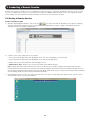
2.4.8 Power Devices
The Power Devices section allows for IP PDUs to be added to the KVM switch. Via the Power Outlets section (See the Power Outlets section
in this manual for details), the NetCommander IP KVM ports can then be mapped to a port on one of these, allowing you to Power Cycle a
port, or turn its power Off/On.
To Add a PDU:
1. From the Configuration section, select the Power Devices tab. The Power Devices page appears.
2. Click the Add button. The Add PDU page opens.
25
2. Web Configuration Interface
3.In PDU Name, type an appropriate name for the PDU you are adding.
4.The Type drop-down menu provides a list of PDUs that are supported by the NetCommander IP. Select your PDU from this list. Based on
your selection, the number of PDU outlets is displayed in the Outlets field.
5. In the Address section, enter in the type of IP Address appropriate for your PDU: IPv4, IPv6, or Host. Note: When using a host name for
an IPv6 address, add the prefix udp6: to it. For example, a host name of host1 should be inputted as udp6:host1.
6.Click OK. The PDU is added to the Power Devices page.
7. Click the Save button at the top of the screen to save your changes.
To Edit an existing PDU:
1. In the Power Devices page, select a PDU from the list and click the Edit button. The Edit PDU page appears.
2. Update the PDU Name, Type, and/or IP fields as required.
3.Click OK. The Power Devices page opens with the modified information.
4. Click the Save button at the top of the screen to save your changes.
To Delete a PDU:
1. In the Power Devices page, select a PDU from the list and click the Delete button. A prompt appears asking you to confirm the deletion
of the selected PDU.
2.Click Yes. The Power Devices page opens, and the PDU no longer appear in the list.
3. Click the Save button at the top of the screen to save your changes.
26
2. Web Configuration Interface
2.4.9 Power Outlets
Once a PDU is added to the KVM via the Power Devices section, you need to assign a NetCommander IP Target Server port to one of the
ports on a PDU to be able to Power Cycle it, or turn its power Off/On. For Target Servers with dual power supplies, you can assign multiple
PDU ports to the same KVM port. In this case, power to both of the Target Server ports will be managed at the same time.
To configure the power outlets:
1. From the Configuration section, select the Power Outlets tab. The Power Outlets page appears.
2.The Name drop-down list contains all of the PDUs that have been added to the KVM. Select the desired PDU. The Power Outlets page
populates according to the number of outlets on the selected PDU.
3. For each outlet on the PDU that has a Target Server connected to it, select from the corresponding Server Name dropdown list the
name of the connected server.
4. Click the Save button at the top of the screen to save your changes.
5. Repeat these steps for each PDU that has been added to the KVM.
27
2. Web Configuration Interface
2.4.10 Serial Ports
The Serial Ports page is where you configure the settings of the serial device(s) that you have connected to the KVM. (See the Serial Pinout
section in this manual for the pinout information.)
To configure the serial port settings:
1. From the Configuration section, select the Serial Ports tab. The Serial Ports page appears.
2. For each serial device connected, enter an appropriate Device Name, and then set the Baud Rate, Parity, Data Bits and Stop Bits
settings accordingly.
3. Click the Save button at the top of the screen to save your changes.
2.4.11 Security
The Security section allows you to configure the security features of the KVM, such as Account Blocking, Password Policy, Idle Timeout, and
Serial Terminal Policy.
To configure the security settings:
1. From the Configuration section, select the Security tab. The Security page appears.
28
2. Web Configuration Interface
2. In the Account Blocking section:
• In the Block after field, enter in the number of unsuccessful login attempts that will be allowed in a given time period. This time period
is set in the attempts within (hr:min) field. Enter into this field the time in hours and minutes.
• In the Block account field, you can select the length of time that an account will be blocked for if it exceeds the number of
unsuccessful login attempts.
• Check the for period (hr:min) checkbox to block the account for a specified period of time. This time period is set in the hours and
minutes fields to the right of the for period (hr:min) checkbox.
• Check the forever checkbox to block the account indefinitely.
3. In the Password Policy section:
• Select the High security password policy checkbox to enable the high security password policy, or leave it unchecked to enable the
standard security policy to apply. Both security policies prohibit the use of the username being included in the password, and have a
maximum character limit of 10. The standard security policy requires only that the password contain at least six characters. The high
security policy requires that the password contain at least eight characters, and that it contain one number, one upper-case letter,
and one of the following special characters: !, @, #, $, %, ^, *, (), _, -, +, =, [], ’, :, ;, ?, /, or {}
• Check the Enable OSD password checkbox to require that a username and password be entered for local user access to the OSD. By
default, a password is not required to access the KVM via the local console. Accounts created in the Web Configuration Interface are
used for both local and remote access.
4. There is only one field in the Idle Timeout portion of the Security page: Disconnect after. In this field, select the amount of time that an
account can be idle before it is automatically disconnected from the system. Select No Timeout to disable this feature.
5.The Serial Terminal Policy portion of the Security page allows you to enable access to the connected serial devices via your own SSH
client (e.g. PuTTY, SecureCRT, etc.). By default, this is disabled, so that an account must open the Web Configuration Interface and
double-click on the serial ports in the My Targets screen list to access them via the NetCommander IP’s internal SSH client. To enable
direct SSH connection, check the Enable direct SSH connection checkbox and enter in the desired TCP port numbers for serial ports 1
and 2 (by default, these are set to 4001 and 4002). You can then access the connected serial devices using your own SSH client by
providing 1) the IP address of the NetCommander IP, 2) the TCP port number for the desired serial device, and 3) your KVM username
and password.
6. After changing any settings in the Security page, click the Save button at the top of the page to save your changes.
7. Upon clicking Save, you will be prompted to reboot the KVM to finish implementation of the new Security settings. Click Yes to proceed.
29
2. Web Configuration Interface
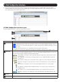
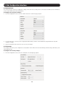
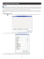
2.4.12 Authentication
The Authentication page allows you to set up remote authentication via RADIUS and/or LDAP/S server. From the Configuration section, select
the Authentication tab to open this page.
Enable Authentication Methods – The section at the top of the Authentication page determines which types of authentication are enabled,
and what priority they take when authenticating a user. For example, when all three methods are enabled in the order of Local, LDAP, and
RADIUS, the KVM’s local user accounts will be checked first during authentication, followed by the LDAP server, and finally the RADIUS
server. By default, Local authentication is permanently enabled and given the highest priority. To enable or disable LDAP and/or RADIUS
authentication, simply check or uncheck the corresponding checkbox. To switch the priority of LDAP and RADIUS authentication, highlight the
desired option by clicking on it, and then click on the Up and Down buttons to move it up and down in the list.
LDAP/S Authentication Settings – Once enabled in the Enabled Authentications Methods section just described, LDAP/S authentication
is set up using the fields in the Authentication Sources section. To setup LDAP/S authentication, make sure that the LDAP tab in the
Authentication Sources section is selected, and then follow the instructions below.
Servers – At the bottom of the page, the Servers section allows you to add LDAP/S servers to the KVM. As with the authentication methods
in the Enabled Authentication Methods section at the top of the page, LDAP/S servers can be listed according to priority. The first server in
the list will be the first one accessed by the KVM during authentication, followed by the second server, etc.. To avoid performance issues
during the authentication process, it is recommended that you add no more than three LDAP/S servers.
30
2. Web Configuration Interface
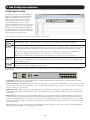
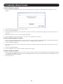
• To add an LDAP/S server to the list, click on the Add button to bring up the Add LDAP Server screen.
• Enter the IPv4, IPv6, or Host address for your LDAP/S server in the corresponding field.
• Select the Port number that is used by the server. The default port number is 389 for LDAP/TLS servers and 636 for LDAPS servers.
• Select from one of three encryption methods to use: No encryption, SSL, or TLS extension.
• Click the OK button to add the server to the list.
• Servers can be edited or deleted by highlighting them in the list and clicking on Edit or Delete. They can be re-ordered according to their
priority by highlighting them and clicking on Up or Down to move them in the list.
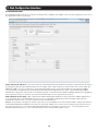
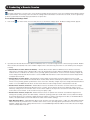
Search – The Search section is where you set the account DN that is used to query the LDAP/S server, and where in the directory to search
during authentication. Reference the following screenshots and descriptions of the Search fields when adding this information.
• Search DN – The Search DN field should be populated with the value of the Distinguished Name attribute for the user account that is
being used to query the Active Directory.
31
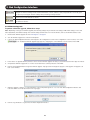
2. Web Configuration Interface
• Search Base – The Search Base field should be populated with the location in the Active Directory in which the search is taking place.
• Search Password – The Search Password field should be populated with the password for the user account that is being used to query
the Active Directory.
• Confirm Password – Re-enter the password into this field to confirm that you have entered it correctly.
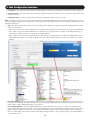
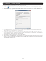
Mode – The Mode section allows you to define the User Name and Access Rights attributes that are used during authentication, as well as
how access rights get assigned to an authenticated account. Reference the following screenshots and descriptions of the Mode fields when
adding this information.
• Type – The Type drop-down menu allows you to choose between three methods of assigning access rights to authenticated accounts:
Basic, User, and Group.
o Basic – When selected, this method authenticates accounts that log in, and gives each account full access rights to the KVM switch.
o User – When selected, this method authenticates accounts that log in, and gives them access rights to the KVM switch based on
those that are assigned to them via a dedicated Access Rights attribute.
o Group – When selected, this method authenticates accounts that log in, and gives them access rights to the KVM switch based on
which Group they belong to. Access rights for Groups are based on those that are assigned to them via a dedicated Access Rights
attribute.
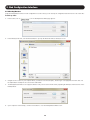
• User Name Attribute – The User Name Attribute field should be populated with the name of the attribute that contains the user login
name for an account. Note: The name that an account uses to log into the KVM switch cannot contain any spaces. If the user login
name contains a space, authentication will not be successful.
• Access Rights Attribute – The Access Rights Attribute field is only needed when User or Group is selected in the Type drop-down
menu. It should be populated with the name of a directory attribute that contains the Access Rights Permission String (See the Access
Rights Permission String section for details), which determines what rights a User or Group has to the KVM. Any directory attribute
that can contain strings may be used to hold the Access Rights Permission String, so you can either re-purpose an existing attribute or
create a brand new one.
32
2. Web Configuration Interface
Access Rights Permission String – In order for access rights to be assigned in User or Group authentication mode, a permission string
must be entered into the directory attribute that is assigned to each User or Group. The name of this attribute must be entered into the
Access Rights Attribute field in the Mode section of the Authentication page. See below for an explanation of how the permission string
needs to be formatted.
Access Category – An Access Category is an entry in the permission string that refers to a particular access right to the KVM switch. The
available Access Categories are listed below.
Note:
1. Access Categories are case sensitive.
2. Access rights must be assigned for each Access Category, regardless of whether User or Admin is assigned as the kvmrole.
• kvmdevice – Refers to the Device Name of a NetCommander IP Multi-User KVM switch. The Device Name of a KVM can be found
in the Device tab of the Configuration section of the web configuration interface (See the Device section in this manual for details). If
kvmdevice is not referenced in the permission string, then access will be allowed to all KVM switches.
• kvmrole – Refers to the type of account, and can be either Admin or User (See the Users section of this manual for details on these
account types).
• kvmports – Refers to the list of ports that an account is allowed to access. Ports are separated in the permission string by a comma.
An asterisk (*) can be used to indicate access to all ports.
• vm_ports – Refers to the list of virtual media ports that an account is allowed to access. Ports are separated in the permission string by
a comma. An asterisk (*) can be used to indicate access to all ports.
• kvmtelports – Refers to the list of serial ports that an account is allowed to access. Ports are separated in the permission string by a
comma. An asterisk (*) can be used to indicate access to all ports.
Sample Permission String
kvmdevice:D1144567,kvmrole:user,kvmports:1,2,5,vm_ports:1,2,kvmtelports:*
The permission string above assigns a User or Group with access to the KVM with Device Name D1144567. The account is given User
permissions and has access to ports 1, 2, and 5 on the KVM, can access virtual media on ports 1 and 2, and can access all serial ports.
RADIUS Authentication Settings – Once enabled in the Enabled Authentications Methods section, RADIUS authentication is set up using
the fields in the Authentication Sources section. To setup RADIUS authentication, make sure that the RADIUS tab in the Authentication
Sources section is selected, and then follow the instructions below. Note: For RADIUS Authentication to work properly, a Tripp Lite dictionary
must be installed on the RADIUS server. The dictionary should be present in the latest dictionaries supplied by FreeRADIUS, or can be
manually downloaded at www.tripplite.com/support.
Servers – At the bottom of the page, the Servers section allows you to add RADIUS servers to the KVM. As with the authentication methods
in the Enabled Authentication Methods section at the top of the page, RADIUS servers can be listed according to priority. The first server
in the list will be the first one accessed by the KVM during authentication, followed by the second server, etc. To avoid performance issues
during the authentication process, it is recommended that you add no more than three RADIUS servers.
• To add a RADIUS server to the list, click on the Add button to bring up the Add RADIUS Server screen.
• Enter the IPv4, IPv6, or Host address for your RADIUS server in the corresponding field.
Note: The Host name should only be used for IPv4 RADIUS servers. For IPv6 RADIUS servers, the IPv6 address should be used instead of
a Host name.
• Select the authentication Port number and Accounting Port number to be assigned to the server. The default authentication port number is
1812, and the default accounting port number is 1813.
33
2. Web Configuration Interface
• Enter and re-enter a shared secret according to the one specified in the RADIUS server.
• Click the OK button to add the server to the list.
• Servers can be edited or deleted by highlighting them in the list and clicking on Edit or Delete. They can be re-ordered according to their
priority by highlighting them and clicking on Up or Down to move them in the list.
Global – The Global section allows you to define the Default Realm of the RADIUS server, and to enable/disable Accounting Support.
• Default Realm – Enter in the Default Realm for the RADIUS server here.
• Enable Accounting Support – Check this checkbox to enable Accounting Support, or leave it unchecked to disable it. When enabled,
Accounting Support will generate Start and Stop accounting events that keep track of when a user accesses a KVM port, and when it
disconnects from it.
RADIUS Access Rights – RADIUS access rights are assigned to accounts by adding a TrippLite-KVM-ACL field into the user account
definition in the user’s file (on FreeRADIUS), or on user settings (under Active Directory), and populating it with a permission string. The
permission string format will be the same as that described in the Access Rights Permission String section of this manual. The only difference
is that it will need to contain the prefix TrippLite-KVM-ACL=, which designates the property used for it under the Tripp Lite Dictionary.
For example, to give an account Admin access to all KVM ports on all KVMs, the following should be added to the user’s file entry on
FreeRADIUS.
account
ClearText-Password=[enter account password here]
Framed-Protocol=PPP
Framed-IP-Address=[enter RADIUS IP here]
Framed-IP-Netmask=255.255.255.0
Framed=MTU=1500
TrippLite-KVM-ACL=kvmrole:admin,kvmports:*
2.4.13 Date & Time
This section describes how to configure the system date and time. The system date and time are used when recording log events (see the
Events section in this manual for details).
To configure the date and time:
From the Configuration section, select the Date & Time tab. The Date & Time page appears.
1. In the Date fields, enter in the current Day, Month and Year.
2. In the Time fields, enter in the current Hour, Minute and Second.
3. Click the Save button at the top of the page to save your changes.
2.5 Password Section
The Password section of the Web Configuration Interface provides a convenient way for an account to change their password.
To change the password:
1. Click on the
icon in the menu bar of the Web Configuration Interface. The Change Password page is displayed.
34
2. Web Configuration Interface
2. In the New Password field, type in a new password, according to the Password Policy set in the Security page of the Configuration
section (see the Security section in this manual for details).
3. In the Confirm Password, retype the new password.
4.Click
. The new password is saved in the system.
2.6 Events Section
The Events section of the Web Configuration Interface allows administrator accounts to view a log of events that take place on the
installation. In the Events page, you can view the log, refresh its information, clear it, and save it to a .csv file, which can be converted to
Excel.
To view the Events Log:
1. Click on the
events displayed.
icon in the menu bar of the Web Configuration Interface. The Events page appears, with a log of all system
To reload the Events Log:
1. With the Events page open, click the
information.
icon in the toolbar. The list of events on the page is refreshed to show the most current
To clear the Events Log:
1. With the Events page open, click the
icon in the toolbar. A prompt appears asking you to confirm the action.
2. Click the Yes button. The Events Log is permanently cleared.
To save the Events Log:
1. With the Events page open, click the
icon in the toolbar. The Save As window appears.
2. Type an appropriate name for the file, and select a location on your computer to save it in. Click the Save button to save the file.
Note: The file will automatically be save as a .csv file, which can be opened in Excel.
35
3. Conducting a Remote Session
A remote session allows accounts IP access to computer/servers and serial devices connected to the KVM. In a remote session, accounts
can access computers/servers, power cycle or turn power to a Target Server Off/On, virtually mount an .iso file, and configure the remote
session settings. The sections that follow explain the features of a remote session, and how to use them.
3.1 Starting a Remote Session
To start a remote session:
1. Open the Web Configuration Interface, and click on the
icon in the menu bar. The My Targets screen appears, displaying
only those ports that the logged-in account is permitted to use. For administrator accounts, a graphic of the KVM’s back panel is
displayed in between the Toolbar and Data Pane.
2. A remote session can be initiated in one of four ways:
• Select a port from the Data Pane of the My Targets screen, and click on the Display icon in the toolbar.
• Select a port from the Data Pane of the My Targets screen, and press the [Enter] key.
• Double-click on a port in the Data Pane of the My Targets screen.
• Administrator’s Only – Double-click on a port in the graphic of the KVM’s back-panel.
Note: A Target Server with a Remote Exclusive Session or Local Exclusive Session status is being accessed by another account in
Exclusive Mode (see the Exclusive Session section in this manual for details), and cannot be accessed. A Target Server with a Remote
Session status is being accessed by another account in Share Mode, which allows for up to 5 users to access the port at the same time
(see the Sharing a Remote Session section in this manual for details).
3. Upon initiating a remote session in one of these four ways, the screen of the selected Target Server appears inside a remote console
window with the remote session toolbar displayed.
36
3. Conducting a Remote Session
3.2 Remote Session Toolbar
The NetCommander IP provides a toolbar that allows a remote session to be manipulated. The features on the toolbar allow you to toggle
between accessible ports, adjust the video settings of the remote session, align the local and remote mouse pointers, etc.. When a remote
session is initiated, the toolbar is displayed briefly in the top-center of the screen, and then collapses to display only a thin bar. To expand
the toolbar, simply move the mouse pointer over the blue bar at the top-center of the screen. The following sections describe the features
available in the remote session toolbar, and how they are used.
3.2.1 Pin Toolbar
– Clicking on the Pin Toolbar icon will toggle between displaying the toolbar constantly and allowing it to disappear after a few seconds.
By default, it disappears after a few seconds.
3.2.2 Session
– Clicking on the Session icon will display a drop-down list of four options; Mount ISO, Unmount ISO, Session Profile, and About.
• Mount ISO – The Mount ISO feature allows you to mount an ISO file to the Target Server as virtual media.
Note:
1. Virtual Media data transfer rates up to 12Mbps are supported. To achieve data transfer rates up to 12Mbps, a B078-101-USB2 must be used.
2. A B078-101-USB-1 can be used to provide Virtual Media support, but only at speeds up to 1Mbps. B078-101-USB and B078-
101-PS2 SIUs are not compatible with Virtual Medial.
3. The ISO file that your are mounting must be located in a Shared Folder of a Samba or NFS file server which is on the same network that the NetCommander IP is connected to.
To mount the ISO as virtual media:
1. Click on the
icon in the remote session toolbar, and choose the Mount ISO option. The Mount ISO window appears.
2. In the Share Name, type in the share name of the ISO file from your Samba or NFS file server. For example, if the desired ISO file has
the path \\hostname\sharedr\file.iso, the Share Name that you should type is: \\hostname\sharedr.
3. In the ISO Path field, type the direct path to the ISO file. In the example of the previous step, the ISO Path is \file.iso.
4. Select one of the following supported file sharing methods:
• Samba (Microsoft Windows)
• NFS (Unix/Linux)
5. For secured file sharing type in a User Name and Password.
6. Click the Mount button. The ISO file is mounted onto the server.
37
3. Conducting a Remote Session
• Unmount ISO – The Unmount ISO feature disconnects an ISO virtual media file that has already been mounted.
To unmount an ISO file:
1. Click on the
action.
icon in the remote session toolbar, and choose the Unmount ISO option. A prompt appears asking you to confirm the
2.Click Yes. The ISO virtual media file is unmounted from the remote server.
• Session Profile – The Session Profile feature allows you to set a few basic parameters for the remote session; Local Mouse Pointer
image, On Connect settings, and Exclusivity.
To set the session profile:
1. Click on the
icon in the remote session toolbar, and choose the Session Profile option. The Session Profile window appears.
2. In the Local Mouse Pointer section, select one of the following options to set the appearance of the Client Computer’s mouse pointer.
• None – Hides the Client Computer’s mouse pointer altogether, so that only the Target Server’s mouse pointer can be seen.
• Dot – Displays the Client Computer’s mouse pointer as a dot.
• Default – Displays the Client Computer’s mouse pointer in the standard format.
3. In the On Connect section, choose amongst the following options:
• Auto hide – When this checkbox is checked, the remote session toolbar will be collapsed upon logging into a remote session. When it
is unchecked, the remote toolbar will remain displayed upon logging in.
• Full Screen – Check this checkbox to display the remote session screen in full screen mode upon logging into a remote session. This
setting takes affect from the next connection onwards. To toggle full screen mode on and off, you can click the Full Screen
icon in
the remote session toolbar. Full Screen mode can also be toggled on/off by pressing [Alt] + [Enter].
• Show Status Bar – Check this checkbox to display the Status Bar at the bottom of the remote session screen. This option is enabled
by default.
38
3. Conducting a Remote Session
4. In the Exclusivity section, check the Exclusive Session checkbox to prevent other accounts from accessing the Target Server port at the
same time. By default, this checkbox is unchecked, and a remote session is initiated in Share Mode, which allows up to 5 accounts
to log into a port at the same time (see the Shared Session section in this manual for details). Note: Although an Exclusive Session
prevents other accounts from remotely logging into a port at the same time as you, administrator accounts still have the ability to
disconnect your session and access the port if desired, and a local account can access the port and disconnect your session.
• About – Selecting the About feature will bring up a screen that displays the NetCommander IP Client Version number and Firmware
Version number.
3.2.3 Video
– Clicking on the Video icon will display a list of four options for managing the remote session’s video: Refresh, Video Adjust, Video
Mode, and Advanced.
• Refresh – Selecting the Refresh feature will regenerate the remote screen to show the most current video. A video refresh may be
necessary when changing the display attributes of a Target Server.
• Video Adjust – Selecting the Video Adjust feature will perform an auto video adjust, which aligns the Target Server’s video so that it
displays properly in the remote session screen.
• Video Mode – In the Video Mode feature, choose amongst the following options. After selecting an option, click the Apply button.
oNormal – Select Normal to display the Target Server video normally, in full color. By default, the video mode is set to Normal.
oGrey Level – Select Grey Level to display the Target Server video in Black and White. In low-bandwidth networks, this can help improve
keyboard and mouse response time by reducing the amount of video data traveling over the network.
• Advanced - Although the Refresh, Video Adjust, and Video Mode features generally provide an automated way for you to optimize the
remote session video, you may want to fine-tune the results. You can use the Advanced video adjustment screen to fine-tune the settings.
39
3. Conducting a Remote Session
To manually adjust the video settings:
1. Click on the
icon in the remote session toolbar, and choose the Advanced option. The Advanced window appears.
2. In the Brightness & Contrast section of the Advanced screen, use the corresponding scales to adjust the brightness and contrast of the
displayed image.
3. In the Offset, Phase and Scale section of the Advanced screen, adjust the following settings accordingly:
• In the H. Offset field, select the horizontal starting position of each line on the displayed image.
• In the V. Offset field, select the vertical starting position of the displayed image.
• In the Phase field, select the point at which each pixel is sampled.
4. In the Filter section of the Advanced screen, select the filter level of the video from the Target Server. A higher filter reduces the noise
level but makes the image coarser. Options are: Auto, No Filter, Low, Medium, and High.
5.The Noise Level section of the Advanced screen displays the amount of video noise present when a static screen is displayed. The
more noise that is present, the slower your keyboard and mouse response time will be. Adjusting the Phase and Scale fields can help
decrease the noise level.
6. When you are done making changes, click the OK button. To exit without saving changes, click on the Restore button first.
3.2.4 Power
– Clicking on the Power icon will display a list of three power management functions that can be performed on the currently selected
Target Server. Select one of these functions to perform it on the Target Server. Upon selecting a power management function, a prompt
appears asking for you to confirm the action. Click Yes to proceed. Note: In order for power management functions to be performed on the
Target Server, it must be mapped to a PDU that has been added to the NetCommander IP Power Devices page (see the Power Devices and
Power Outlets sections in this manual for details).
• Power Cycle – The Power Cycle function sends a signal to the Target Server to power it down and then back up again.
• Power Up – The Power Up function sends a signal to the Target Server to turn its power on.
• Power Down – The Power Down function sends a signal to the Target Server to turn its power off.
40
3. Conducting a Remote Session
3.2.5 Keys
– Clicking on the Keys icon will display a list of predefined key sequences (e.g. Ctrl + Alt + Delete) that can be performed on the Target
Server. By default, performing these key sequences on the Client Computer’s keyboard sends the command to the Client Computer. Opening
the Keys menu and clicking on one of the predefined commands will send it directly to the Target Server. In addition, the Keys feature allows
you to add commands to the Keys drop-down list, and create commands that are not already provided.
Note: The Predefined and Custom Keys that are added to the Special Key Manager are unique to each port. You will need to customize the
keyboard sequences that are available for each port. Once you do this, you will not need to do it again, except to add or remove keyboard
sequences.
To add a keyboard sequence:
1. Click on the
icon in the remote session toolbar, and choose the Special Keys option. The Special Key Manager window appears.
2. Click the Add Predefined button to pull up a list of predefined command sequences.
3. Select a key sequence and click OK. The sequence appears in the Special Key Manager window.
4. In the Special Key Manager window, click OK. The sequence appears in the Keys drop-down list.
41
3. Conducting a Remote Session
To record a keyboard sequence:
1. Open the Special Key Manager window and click the Record New Custom Key button. The Record New Custom Key macro screen
appears.
2. In the Label field, type a name for the new key sequence.
3. Click the Start Recording button.
4. On your keyboard, press the keys to include in the key sequence. The names of the pressed keys appear in the provided area as you
type them.
5. When done with the sequence, click the Stop Recording button.
6. Click the OK button. The new key sequence is now on the list of predefined key sequences.
To edit a predefined keyboard sequence:
1. Open the Special Key Manager window, select the desired key sequence, and then click the Edit button. The Record New Custom Key
macro screen appears, with the name of the key sequence to edit appearing in the Label field.
2. Click the Start Recording button.
3. On your keyboard, press the keys to include in the key sequence. The names of the pressed keys appear in the provided area as you
type them.
4. Click the Stop Recording button.
5. Click the OK button. The key sequence definition is updated in the system.
To delete a keyboard sequence:
1. Open the Special Key Manager window, select the desired key sequence, and then click the Delete button. A prompt appears asking you
to confirm the action. Note: To select a group of keys, highlight the first key in the group, press and hold down the [Shift] button, and
then highlight the last key in the group.
2. Click Yes to proceed.
42
3. Conducting a Remote Session
3.2.6 Mouse
– Clicking on the Mouse icon allows you to select the Mouse Settings mode being used, as well as to manually adjust settings related to
mouse synchronization. The following section describes the settings found via the Mouse icon and how to use them, as well as general tips
for mouse synchronization and improving keyboard/mouse response time.
To set the Mouse Settings mode:
1. Click on the
icon in the remote session toolbar, and choose the Mouse Settings option. The Mouse Settings window appears.
2. By default, the Absolute Mouse Position (Microsoft Windows) mode is selected for Target Servers connected using a USB SIU. Relative
Mouse Position (OS-Specific) mode is the default for Target Servers connected using a PS/2 SIU. You can manually select among the
following:
• Absolute Mouse Position (Microsoft Windows) – Absolute Mouse Position (Microsoft Windows) mode should be used if the
Target Server’s operating system is Windows ME or later. The Absolute Mouse Position (Microsoft Windows) function automatically
sends the mouse coordinates to the remote session, providing optimal synchronization. You do not need to manually configure any
mouse settings when Absolute Mouse Position is selected. Note: Absolute Mouse Position mode cannot be used for Target Servers
connected with a PS/2 SIU.
• Absolute Mouse Position (Linux) – Absolute Mouse Position (Linux) mode should be used if the Target Server uses a Linux
operating system, such as Ubuntu. The Absolute Mouse Position (Linux) function automatically sends the mouse coordinates to the
remote session, providing optimal synchronization. You do not need to manually configure any mouse settings when Absolute Mouse
Position is selected. Note: Absolute Mouse Position mode cannot be used for Target Servers connected with a PS/2 SIU.
• Relative Mouse Position, OS-Generic – Relative Mouse Position, OS-Generic mode should be used if the other mouse settings
modes are not performing satisfactorily. When this mode is in effect, the user must focus the mouse within the remote session
window by clicking inside of it. From then on the mouse remains captured, and any mouse movement will remain within the borders
of the remote session window. To exit out of this mode, press [Ctrl] + [Alt].
• Relative Mouse Position, OS-Specific – Relative Mouse Position, OS-Specific mode should be used when the Target Server is
running Linux operating systems other than Ubuntu, or Windows operating systems prior to ME. When selected, additional settings
are provided that allow you to manually configure the Mouse Settings according to your Target Server’s OS (see the Relative Mouse
Position, OS-Specific Mode section in this manual for details on the available settings).
• Apple Macintosh Mouse – Apple Macintosh Mouse mode should be used if the Target Server is a Mac. The Apple Macintosh Mode
function automatically sends the mouse coordinates to the remote session, providing optimal synchronization. You do not need to
manually configure any mouse settings when this mode is selected. Note: Apple Macintosh Mouse mode cannot be used for Target
Servers connected with a PS2 SIU.
43
3. Conducting a Remote Session
To configure settings in Relative Mouse Position, OS-Specific mode:
1. Click on the
icon in the remote session toolbar, and choose the Mouse Settings option. The Mouse Settings window appears.
2. Check the Relative Mouse Position, OS-Specific checkbox. Additional settings appear that allow you to manually configure the mouse
settings according to your Target Server’s OS and mouse type.
3. In the Operating System field, select your Target Server’s operating system from the drop-down menu. Instructions and slider bars
appear on the screen according to the chosen operating system.
4. Configure these settings to match those shown in the Target Server’s Mouse Properties window. Note: If the mouse settings of the
remote computer have ever been changed (even if they were changed and then returned to the original settings) uncheck the Default
checkbox and edit the settings to match those of the Target Server.
5. Check the USB checkbox if the Target Server is connected with a USB SIU.
6. When you are done configuring all settings, click the OK button to close out of the Mouse Settings window. Upon moving the mouse in
the remote session screen, the pointers should align. If needed, use the Align feature (see the Align section in this manual for details)
of the Mouse drop-down in the toolbar.
44
3. Conducting a Remote Session
To align the mouse pointers:
Note: The Align function is only available in the Mouse drop-down menu when the Mouse Settings mode is set to Relative Mouse Position.
When logging into the KVM or accessing a new port, the local and remote mouse pointers may not be aligned. This does not always mean
that they are not set up properly. Click on the Align feature in the Mouse drop-down menu of the toolbar to bring them together.
1. Click on the
icon in the remote session toolbar, and choose the Align option (or press [Ctrl] + [M]). The mouse pointers align.
2. If the mouse pointers do not align, try manually configuring the mouse settings (see the Mouse Settings Mode and Relative Mouse
Position Mode sections in this manual for details).
To calibrate the mouse pointers:
Note:
• The Calibrate function is only available in the Mouse drop-down menu when the Mouse Settings mode is set to Relative Mouse Position.
• The Calibrate function works with computers running Linux, or Windows NT4, 98 or 2000.
1. Click on the
icon in the remote session toolbar, and choose the Calibrate option. The mouse pointers align.
2. If the mouse pointers do not align, try using the Align function, or manually configuring the mouse settings (see the Mouse Settings
Mode and Relative Mouse Position Mode sections in this manual for details).
Mouse Synchronization and Keyboard/Mouse Response Time Tips:
If the local and remote mouse pointers do not align, or your keyboard/mouse response time is slow, try the following:
• Go into the Target Server’s Mouse Properties screen and make sure that the Enhanced Pointer Precision setting is unchecked. If checked,
the local and remote mouse pointers will not align. The image below shows this screen from a Windows Vista computer.
• There are times when a Video Adjust does not properly align the Target Server’s video in the remote session screen. If the screen is not
aligned properly (you will see a black bar on a side of the remote screen, and part of the remote screen will not be displayed), the local
and remote mouse pointers will not align. Try performing another Video Adjust to bring the screen into alignment. If this still does not work,
you will need to manually adjust the H. Offset and/or V. Offset settings in the Advanced screen to bring the screen into alignment. (See the
Advanced video settings section in this manual for details.)
• If you are using non-shielded Cat5/6 cable, try using Tripp Lite N105-Series Cat5e shielded patch cable. Any noise that exists in the
cabling can affect local and remote mouse alignment, and switching to shielded cabling eliminates that noise.
• Change the Video Mode (see the Video Mode section in this manual for details) to decrease the amount of information being transferred
over the network. The less data that is being sent, the faster the keyboard/mouse response time. In particular, the Grey Level setting can
help improve keyboard and mouse response time.
• Go to the display settings section of the Target Server and lower the video resolution, refresh rate and color settings.
• If the Target Server has a graphic desktop background, change it to a solid color background.
• If the target server is in BIOS boot mode, the ability to change mouse mode settings is temporarily disabled. When BIOS mode exits,
mouse mode settings can be opened and settings edited.
45
3. Conducting a Remote Session
3.2.7 Server/Serial
– Clicking on the Server/Serial icon displays a drop-down list of ports that are accessible to the currently logged-in account. Simply
select a port to access it.
3.2.8 Full Screen
– Clicking on the Full Screen icon (or pressing [Alt] + [Enter]) toggles full screen mode on/off.
3.2.9 Logout
– Clicking the Logout icon closes your remote session, but does not log you out of the Web Configuration Interface.
3.3 Shared Session
By default, a remote session is accessed in Share Mode, unless the Exclusive Session checkbox in the Session Profile screen is checked
(see the Session Profile section in this manual for details). Share Mode gives access to up to 5 accounts to the same port at the same
time, allowing them to collaborate their work and share a remote session. All accounts in a shared session see video at the same time and
share the Keyboard/Mouse control. Keyboard/mouse commands are performed by whichever account takes control. Once an account stops
using the keyboard/mouse, another account can immediately start using it. When initiating a remote session in Share Mode, the following
message appears:
3.4 Exclusive Session
When in a remote session without any other logged in accounts, you can prevent other accounts from accessing the same port as you by
checking the Exclusive Session checkbox in the Session Profile screen (see the Session Profile section of this manual for details). An account
accessing a Target Server in an Exclusive Session is the only one who can see the video and control the Keyboard/Mouse; other accounts
are prevented from accessing the port at the same time. Note: Exclusive Mode prevents accounts from remotely accessing a port at the
same time; however, administrator accounts still have the ability to disconnect a session and then take over access to the port, and a local
account can access the port and disconnect your session.
46
4. Local Console
This chapter explains how to operate the NetCommander IP via the local console. The local console allows you to access connected
computer/servers, configure the KVM’s network settings, and to configure some more basic settings specific to local access.
To display the OSD:
1. From the local keyboard, press the left Shift key twice. The
OSD Main window appears.
Lines with sun icons in the PM column show active computers/
servers. A computer that is connected, but is powered-off, does
not have a sun icon. When a server is busy (when an account is
accessing it in an Exclusive Session), the entire line appears in red
characters.
Navigating the OSD:
• To move the highlight bar throughout the list, press the [h] and [i] arrow keys.
• To jump from one column to the next (when relevant), press the [Tab] key.
• To exit the OSD or return to a previous window within the OSD, press the [Esc] key.
To select a computer:
1. Navigate to the desired port using the [h] and [i] arrow keys, or type the two-digit port number of the desired computer.
2. Press the [Enter] key. The selected computer is accessed.
4.1 Move Label (F1)
When a Target Server is accessed via the local console, a Confirmation Label appears briefly, displaying the port number and name of the
Target Server being accessed. After a few seconds, the Confirmation Label disappears. You can position the Confirmation Label anywhere on
the screen using the OSD’s MOVE LABEL (F1) function.
1. Open the OSD and highlight the desired computer using the [h] and [i] arrow keys.
2. Press the [F1] key. The selected port’s video and Confirmation Label appear.
3. Use the arrow keys to move the label to a desired position on the screen.
4. Press the [Esc] key to save the position and exit.
4.2 Tuning (F5)
You can tune the image of any Target Server using the OSD’s TUNING (F5) function.
1. Open the OSD and highlight the desired computer using the [h] and [i] arrow keys.
2. Press the [F5] key. The selected port’s video and the Image Tuning Label appears.
3. Use the [h] and [i] arrow keys to adjust the image.
4. When the image is satisfactory, press the [Esc] key.
47
4. Local Console
4.3 Power Management
As with the Web Configuration Interface, you are able to perform power management functions via the local console. The power
management functions available to you are described below. Note: In order to perform power management actions on a port, it must be
configured to match a power outlet of a power device that has been added to the KVM. (See the Power Device and Power Outlets sections
of this manual for details)
Cycle – Choose the Cycle option to perform a power cycle on the computer/server connected to the selected port.
Up –Choose the Up option to turn the power to the computer/server connected to the selected port on.
Down – Choose the Down option to turn the power to the computer/server connected to the selected port off.
To Power Manage a computer:
1. Open the OSD and highlight the desired computer using the [h] and [i] arrow keys.
2. Press the [Enter] key to access the highlighted computer.
3. When accessing the computer, press and release the left [Shift] key, and then press and release the [F12] key. Note: This hotkey
combination will change if the hotkey combination used to open the OSD is changed. When the OSD hotkey is [Shift] + [Shift], the
Power Management hotkey is [Shift] + [F12]. When the OSD hotkey is [Ctrl] + [Ctrl] or [Ctrl] + F11], the Power Management hotkey is
[Ctrl] + [F12]. When the OSD hotkey is [Print Screen] + [Print Screen], the Power Management hotkey is [Print Screen] + [F12].
4.The Power Control dialog box appears.
5. Highlight the desired function using the [h] and [i] arrow keys, and then press the [Enter] key.
6. A prompt appears, asking you to confirm the operation.
7. To perform the selected operation, choose Yes. The power command is sent.
4.4 (F2) Setting
The OSD’s F2 – SETTING menu allows you to configure the following settings:
• Device IP address
• OSD hotkey
• Keyboard language
• DDC
To open the FW – SETTING screen, simply open the OSD and press
the [F2] key.
You can navigate through the page by pressing the [Tab] key. At the
bottom of the window, pressing the [Tab] key will take you back to
the top of the window. Change settings by typing in the selected
area or by pressing the spacebar – whichever is relevant.
48
4. Local Console
To set the IPv4 address via the local console OSD:
1. From the local console, press the left [Shift] key twice to open
the OSD.
2. Press the [F2] key to open the Settings menu.
3. In the Settings menu, press the [Tab] key until the DHCP field is
highlighted. Press the [Spacebar] key to toggle the DHCP field
from Enabled to Disabled.
4. Pressing the [Tab] key to navigate to the additional fields, type
in the desired IP Address, Subnet Mask, Gateway, and DNS
Server Address (Optional).
5. Once the IP address is satisfactory, press the [Esc] key to save
your changes. This will require that the KVM be rebooted to
save the new settings.
To set the IPv6 address via the local console OSD:
1. From the local console, press the left [Shift] key twice to open
the OSD.
2. Press the [F2] key to open the Settings menu, and then press
the [F2] key again to open the IPv6 Settings menu.
3. In the IPv6 Settings menu, with the Mode field at the top of the
screen highlighted, press the [Spacebar] key to toggle between
DHCP, Stateless, and Static. DHCP is selected by default, and
automatically assigns an IP address via the IPv6 DHCP server.
Stateless is an option for networks with a compliant router that
automatically assigns an IP address based on the MAC address
of the unit. Static allows you to manually assign an IP address.
4. Pressing the [Tab] key to navigate to the additional fields, type
in the desired IP Address, Gateway, and DNS Server Address
(Optional).
5. Once the IP address is satisfactory, press the [Esc] key twice
to exit and save your changes. This will require that the KVM be
rebooted to save the new settings.
49
4. Local Console
Changing the Hotkey:
By default, the hotkey combination used to open the OSD is [Shift] + [Shift]. You can change this hotkey in the F2 – SETTING menu to use
any of the following. Note: The left [Shift] hotkey must be used; the right [Shift] key will not work. If you set the hotkey to [Ctrl] + [Ctrl] or
[Ctrl] + [F11], the left [Ctrl] key must be used.
• [Shift] + [Shift]
• [Ctrl] + [Ctrl]
• [Ctrl] + [F11]
• [Print Screen] + [Print Screen]
To change the hotkey:
1. In the F2 - SETTING window, navigate to the Hotkey field.
2. Press the [Spacebar] key to toggle between the available options.
3. After choosing the desired hotkey, press the [Esc] key to exit the F2 – SETTING window.
To change the keyboard language:
By default, the keyboard language is preset to US English. You can change the keyboard language to French (FR) or German (DE). Note: This
refers to the OSD keyboard language and not the computer keyboard language.
To change the keyboard language:
1. In the F2 - SETTING window, navigate to the Keyboard Language field.
2. Press the [Spacebar] key to toggle between the available options.
3. After choosing the desired language, press the [Esc] key to exit the F2 – SETTING window.
Inputing and Updating DDC Information:
Display Data Channel (DDC) is a VESA standard for communication between a monitor and a video adapter. The SIU emulates the DDC
information to the connected computer. When first installing the NetCommander IP system, emulate the DDC information of the connected
monitor into the memories of all connected SIUs.
To input the DDC information:
1. In the F2 - SETTING window, press the [F10] key. The text
“Please wait” flashes a few times and disappears. The monitor’s
DDC information is sent to all SIUs.
You should update the DDC information in any of the following
circumstances:
• When replacing the monitor connected to the NetCommander IP
• When adding a new SIU to the system
• When reconnecting an existing SIU that was temporarily used in a
different system
50
5. Serial Port Pinout
Note: When connecting a Cisco device, use Cisco rolled cable.
Serial Port 1:
Serial Port 2:
Pin 1: RTS
Pin 1: RTS
Pin 2: DTR
Pin 2: DTR
Pin 3: TX
Pin 3: TX
Pin 4: GND
Pin 4: GND
Pin 5: GND
Pin 5: GND
Pin 6: RX
Pin 6: RX
Pin 7: DSR (pins 7 and pin 2 are shorted inside the unit)
Pin 7: DSR
Pin 8: CTS
Pin 8: CTS
6. Security Certificate Installation
When remotely logging in to the KVM, you may get security warnings from your Web browser and/or Java pop-up stating that the connection
to the website cannot be trusted. This occurs because the KVM’s security certificate is not among the browser and/or Java control panel’s
list of trusted certificates. To add the certificate to the list of trusted certificates, follow the steps in this section. Once installed, the security
warning will no longer appear. Note: If the IP address of the KVM switch is changed, you will need to reinstall the security certificate.
Browser Security
The following steps apply to Internet Explorer 9, but may also be used with other Web browsers. Note: You may need to run Internet Explorer
as an Administrator to install the security certificate.
1. Upon logging into the KVM, a screen will appear stating that there is a problem with the website’s security certificate. Click on Continue
to this website (not recommended).
2. A URL bar will appear with a Certificate error message.
51
6. Security Certificate Installation
3. Click on the Certificate error message to display the Certificate Invalid prompt.
4. Click on the View certificates option at the bottom of the prompt to redirect to the Certificate screen.
52
6. Security Certificate Installation
5. Click on the Install Certificate button to bring up the Certificate Import Wizard, then click the Next button.
6. Select the option to Place all certificates in the following store, then click the Browse button. Highlight the Trusted Root Certification
Authorities folder.
7. Click OK. You will be redirected back to the previous screen. Click Next, followed by Finish. Upon clicking Finish, you will be prompted to confirm installation of the certificate.
8. Click Yes to complete the certificate’s installation.
53
6. Security Certificate Installation
Java Security
The following steps apply to Internet Explorer 9 and Java version 1.7.0_45, but may also be used with other Web browsers and Java
versions. Note: You may need to run Internet Explorer as an Administrator to install the security certificate.
1. Open your Web browser and login to the KVM. If the KVM certificate has not yet been installed in the browser, a URL bar with a
Certificate error message will appear. Click on the Certificate error or Security Lock icon in the toolbar to pull up the Certificate screen.
2. Click on the View Certificates option. When the Certificate window appears, click on the Details tab.
54
6. Security Certificate Installation
3. In the Details tab page, click on the Copy to File button. The Certificate Export Wizard appears.
4.Click Next, accepting the default values until you get to the File to Export page.
5. Click the Browse button to navigate the location you want to save the certificate file, and then type a name into the File name field. Click Next to go back to the File to Export screen, where the file path will be entered.
55
6. Security Certificate Installation
6. Click the Next button, followed by the Finish button on the next page to complete export of the KVM certificate.
7. Navigate to your computer’s Control Panel window and open the Java Control Panel.
8. Click on the Security tab, then click the Manage Certificates button.
9. In the Certificate type drop-down menu at the top of the screen, select the Secure Site option.
10. Click the Import button and navigate to the location where the KVM certificate file is saved. Click OK to add the KVM certificate to the Secure Sites list to complete installation.
56
7. Technical Specifications
Specification
Description
Operating systems
Target Server – Windows and Linux
Client computer – Windows with Internet Explorer, Firefox, or Chrome browsers. Linux with Firefox or
Chrome browsers.
Max Resolution
1920 x 1080 (Local console monitor on B070- Series supports a max video resolution of 1366 x 768)
Distance from Switch to SIUs
Up to 100 ft. (30 m.)
Security
SSL, high grade 128-bit AES encryption
Connections
Ethernet – (x2) RJ45 – 10/100 Mbps
Serial – (x2) RJ45
Local KVM connection (B072-Series Only) – VGA (HD15); Keyboard/Mouse (x2) USB
Server – (x16) RJ45 – 116IP / (x8) RJ45-108IP
Power input
100-240 VAC, 50/60 Hz
Operating temperature
0°C to 40°C / 32° to 104°F
Storage temperature
-40°C to 70°C / -40°F to 158°F
Humidity
80% non-condensing relative humidity
Specification
B078-101-PS2 SIU
B078-101-USB-1
B078-101-USB2
Connections
VGA – HD15
KM – (x2) MiniDin6
System – RJ45
VGA – HD15
KM – USB
System – RJ45
VGA – HD15
KM – USB
FVM – USB
System – RJ45
Power
From Keyboard port
From USB port
From USB port
57
8. Video Resolution and Refresh Rates
Hz
56
60
x
640x480
65
66
70
72
x
x
x
x
75
x
x
76
x
x
x
1024x768
x
85
86
x
x
720x400
800x600
73
x
x
x
x
x
x
x
x
x
1152x864
x
1152x900
1280x720
x
1280x768
x
1280x960
x
1280x1024
x
1600x1200
x
1920x1080
x
1920x1200
x
x
x
x
x
x
x
x
Note: The local console monitor on the B070-008-19-IP and B070-16-19-IP supports video resolutions up to 1366 x 768.
9. Warranty and Product Registration
Limited Warranty
TRIPP LITE warrants its products to be free from defects in materials and workmanship for a period of two (2) years (B072-008-1-IP and B072-016-1-IP) or one (1) year
(B070-008-19-IP and B070-016-19-IP) from the date of initial purchase. TRIPP LITE’s obligation under this warranty is limited to repairing or replacing (at its sole option) any such
defective products. To obtain service under this warranty, you must obtain a Returned Material Authorization (RMA) number from TRIPP LITE or an authorized TRIPP LITE service
center. Products must be returned to TRIPP LITE or an authorized TRIPP LITE service center with transportation charges prepaid and must be accompanied by a brief description of
the problem encountered and proof of date and place of purchase. This warranty does not apply to equipment which has been damaged by accident, negligence or misapplication
or has been altered or modified in any way.
EXCEPT AS PROVIDED HEREIN, TRIPP LITE MAKES NO WARRANTIES, EXPRESS OR IMPLIED, INCLUDING WARRANTIES OF MERCHANTABILITY AND FITNESS FOR A PARTICULAR
PURPOSE. Some states do not permit limitation or exclusion of implied warranties; therefore, the aforesaid limitation(s) or exclusion(s) may not apply to the purchaser.
EXCEPT AS PROVIDED ABOVE, IN NO EVENT WILL TRIPP LITE BE LIABLE FOR DIRECT, INDIRECT, SPECIAL, INCIDENTAL OR CONSEQUENTIAL DAMAGES ARISING OUT OF THE USE OF
THIS PRODUCT, EVEN IF ADVISED OF THE POSSIBILITY OF SUCH DAMAGE. Specifically, TRIPP LITE is not liable for any costs, such as lost profits or revenue, loss of equipment, loss
of use of equipment, loss of software, loss of data, costs of substitutes, claims by third parties, or otherwise.
PRODUCT REGISTRATION
Visit www.tripplite.com/warranty today to register your new Tripp Lite product. You’ll be automatically entered into a drawing for a chance to win a FREE Tripp Lite product!*
* No purchase necessary. Void where prohibited. Some restrictions apply. Open to U.S. residents only. See www.tripplite.com for details.
FCC Notice, Class A
This device complies with part 15 of the FCC Rules. Operation is subject to the following two conditions: (1) This device may not cause harmful interference, and (2) this device must
accept any interference received, including interference that may cause undesired operation.
Note: This equipment has been tested and found to comply with the limits for a Class A digital device, pursuant to part 15 of the FCC Rules. These limits are designed to provide
reasonable protection against harmful interference when the equipment is operated in a commercial environment. This equipment generates, uses, and can radiate radio frequency
energy and, if not installed and used in accordance with the instruction manual, may cause harmful interference to radio communications. Operation of this equipment in a
residential area is likely to cause harmful interference in which case the user will be required to correct the interference at his own expense. The user must use shielded cables and
connectors with this equipment. Any changes or modifications to this equipment not expressly approved by Tripp Lite could void the user’s authority to operate this equipment.
WEEE Compliance Information for Tripp Lite Customers and Recyclers (European Union)
Under the Waste Electrical and Electronic Equipment (WEEE) Directive and implementing regulations, when customers buy new electrical and electronic equipment
from Tripp Lite they are entitled to:
• Send old equipment for recycling on a one-for-one, like-for-like basis (this varies depending on the country)
• Send the new equipment back for recycling when this ultimately becomes waste
Tripp Lite follows a policy of continuous improvement. Specifications are subject to change without notice.
1111 W. 35th Street, Chicago, IL 60609 USA • www.tripplite.com/support
58
14-09-174 • 93-32D5_revC