1
K R A ME R E LE CT R O N IC S L TD .
USER MANUAL
MODEL:
VS-62H
6x2 HDMI Matrix Switcher
P/N: 2900-300170 Rev 1
Contents
1
Introduction
1
2
2.1
2.2
2.3
3
3.1
Getting Started
Achieving the Best Performance
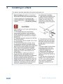
Safety Instructions
Recycling Kramer Products
Overview
Using the IR Transmitter
2
2
3
3
4
5
4
Defining the VS-62H 6x2 HDMI Matrix Switcher
6
5
Installing in a Rack
8
6
6.1
6.2
6.3
7
7.1
7.2
7.3
7.4
Connecting the VS-62H 6x2 HDMI Matrix Switcher
Connecting a Serial Controller to the VS-62H via RS-232
Connecting to the VS-62H via Ethernet
Connecting the Remote Contact-closure Switches
Principles of Operation
Automatic Signal Detection
Input Switching Modes
EDID Operation
Step-in Functionality
9
10
10
13
15
15
15
16
16
8
8.1
8.2
8.3
8.4
8.5
9
9.1
9.2
9.3
10
10.1
10.2
10.3
10.4
10.5
10.6
11
Operating the VS-62H 6x2 HDMI Matrix Switcher
Switching an Input to an Output
Acquiring an EDID from an Output
Muting and Unmuting the Outputs
Locking and Unlocking the Front Panel Buttons
Generating a Test Pattern
Configuring and Maintaining the VS-62H
Setting the DIP-switches
Resetting the VS-62H to Factory Default Settings
Upgrading the Firmware
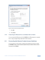
Operating the VS-62H Remotely via the Web Pages
Browsing the VS-62H Web Pages
The Routing Page
The EDID Page
The Device Setting Page
The Firmware Upgrade Page
The About Us Page
Wiring the Twisted Pair RJ-45 Connectors
17
17
17
18
19
19
21
21
22
22
23
23
25
30
32
33
34
35
12
Technical Specifications
36
13
Default Communication Parameters
37
14
Default EDID
38
15
15.1
15.2
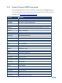
Protocol 3000
Kramer Protocol 3000 Syntax
Kramer Protocol 3000 Commands
40
40
43
VS-62H - Contents
i
Figures
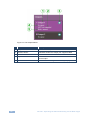
Figure 1: VS-62H 6x2 HDMI Matrix Switcher Front Panel
Figure 2: VS-62H 6x2 HDMI Matrix Switcher Rear Panel
Figure 3: Connecting the VS-62H 6x2 HDMI Matrix Switcher
Figure 4: Local Area Connection Properties Window
Figure 5: Internet Protocol Version 4 Properties Window
Figure 6: Internet Protocol Properties Window
Figure 7: Remote Contact-closure Switch Connections
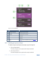
Figure 8: Available Test Patterns
Figure 9: The Loading Page
Figure 10: The General Info Page
Figure 11: The Lock Button
Figure 12: The Routing Page
Figure 13: The Output Buttons
Figure 14: The Input Buttons
Figure 15: The Remote Device Control Window
Figure 16: Test Pattern Tab
Figure 17: The EDID Page
Figure 18: The Device Setting Page
Figure 19: The Firmware Upgrade Page
Figure 20: The About Us Page
Figure 21: TP Pinout Wiring
ii
6
7
9
11
12
13
14
20
23
24
24
25
26
27
28
29
30
32
33
34
35
VS-62H - Introduction
1
Introduction
Welcome to Kramer Electronics! Since 1981, Kramer Electronics has been
providing a world of unique, creative, and affordable solutions to the vast range of
problems that confront video, audio, presentation, and broadcasting professionals
on a daily basis. In recent years, we have redesigned and upgraded most of our
line, making the best even better!
Our 1,000-plus different models now appear in 11 groups that are clearly defined
by function: GROUP 1: Distribution Amplifiers; GROUP 2: Switchers and Routers;
GROUP 3: Control Systems; GROUP 4: Format/Standards Converters; GROUP 5:
Range Extenders and Repeaters; GROUP 6: Specialty AV Products; GROUP 7:
Scan Converters and Scalers; GROUP 8: Cables and Connectors; GROUP 9:
Room Connectivity; GROUP 10: Accessories and Rack Adapters and GROUP 11:
Sierra Video Products.
Congratulations on purchasing your Kramer VS-62H 6x2 HDMI Matrix Switcher
which is ideal for the following typical applications:
Conference rooms
Education
Hospitality
VS-62H - Introduction
1
2
Getting Started
We recommend that you:
Unpack the equipment carefully and save the original box and packaging
materials for possible future shipment
Review the contents of this user manual
i
2.1
Go to http://www.kramerelectronics.com/support/product_downloads.asp
to check for up-to-date user manuals, application programs, and to check if
firmware upgrades are available (where appropriate).
Achieving the Best Performance
To achieve the best performance:
Use only good quality connection cables (we recommend Kramer highperformance, high-resolution cables) to avoid interference, deterioration in
signal quality due to poor matching, and elevated noise levels (often
associated with low quality cables)
Do not secure the cables in tight bundles or roll the slack into tight coils
Avoid interference from neighboring electrical appliances that may adversely
influence signal quality
Position your VS-62H away from moisture, excessive sunlight and dust
!
2
This equipment is to be used only inside a building. It may only be
connected to other equipment that is installed inside a building
VS-62H - Getting Started
2.2
Safety Instructions
!
2.3
Caution:
There are no operator serviceable parts inside the unit
Warning:
Use only the power cord that is supplied with the unit.
Do not open the unit. High voltages can cause
electrical shock! Servicing by qualified personnel only
Warning:
Disconnect the power and unplug the unit from the wall
before installing
Recycling Kramer Products
The Waste Electrical and Electronic Equipment (WEEE) Directive 2002/96/EC
aims to reduce the amount of WEEE sent for disposal to landfill or incineration by
requiring it to be collected and recycled. To comply with the WEEE Directive,
Kramer Electronics has made arrangements with the European Advanced
Recycling Network (EARN) and will cover any costs of treatment, recycling and
recovery of waste Kramer Electronics branded equipment on arrival at the EARN
facility. For details of Kramer’s recycling arrangements in your particular country
go to our recycling pages at http://www.kramerelectronics.com/support/recycling/.
VS-62H - Getting Started
3
3
Overview
The VS-62H is a high quality, 6x2 matrix switcher for HDMI signals. It reclocks and
equalizes the signals and can route any input to either or both outputs
simultaneously.
In particular, the VS-62H features:
Up to 8.91Gbps data rate (2.97Gbps per graphics channel)
Suitable for resolutions up to UXGA and 4K x 2K
Support for HDCP (High Definition Digital Content Protection)
True video clock detection
Automatic switching modes (last connected and priority switching)
HDMI Support – 3D, Deep Color, x.v.Color™, Lip Sync , ARC, HEAC passthrough, Dolby® TrueHD, Dolby Digital Plus, DTS−HD®, and 7.1 multichannel audio
I-EDIDPro™ Kramer Intelligent EDID Processing™ – Intelligent EDID
handling & processing algorithm ensures Plug and Play operation for HDMI
systems
Programmable step-in functionality when used in conjunction with
compatible step-in devices, such as the SID-X3N (using an HDMI cable that
supports HEC, the HDMI Ethernet Channel)
Non-volatile EDID storage
Kramer reKlocking™ & Equalization Technology that rebuilds the digital
signal to travel longer distances
Static or dynamic DHCP IP addressing
Embedded Web pages that provide remote configuration and operation
A lock button to prevent unwanted tampering with the buttons on the front
panel
4
Support for Kramer Protocol 3000
VS-62H - Overview
You can control the VS-62H using the front panel buttons, or remotely via:
RS-232 serial commands transmitted by a PC, touch screen system or other
serial controller
3.1
The Kramer RC-IR3 infrared, remote control transmitter
A PC connected via a LAN to the Ethernet port on the VS-62H
An optional, external, remote IR receiver (see Section 3.1)
Using the IR Transmitter
You can use the RC-IR3 IR transmitter to control the machine via the built-in IR
receiver on the front panel or, instead, via an optional external IR receiver (for
example, P/N C-A35M/IRR-50). The external IR receiver can be located up to 15m
away from the machine. This distance can be extended to up to 60m when used
with three extension cables (for example, P/N C-A35M/A35F-50).
Before using the external IR receiver, be sure to arrange for your Kramer dealer to
insert the internal IR connection cable (for example, P/N: 505-70434010-S) with
the 3.5mm connector that fits into the REMOTE IR opening on the rear panel.
Connect the external IR receiver to the REMOTE IR 3.5mm connector.
VS-62H - Overview
5
4
Defining the VS-62H 6x2 HDMI Matrix
Switcher
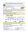
Figure 1 defines the front panel of the VS-62H.
Figure 1: VS-62H 6x2 HDMI Matrix Switcher Front Panel
#
Feature
1
IR LED
2
IR Sensor
3
6
Function
Lights yellow when receiving an IR signal
Signal receiver for the infrared remote control transmitter
TO OUT 2 1~6 Press one of the six inputs to switch it to Output 2
(see Section 8.1).
Press the currently selected input button to mute the output
4
INPUT
SELECTOR
Buttons
5
MUTE Button
Press to toggle mute of both output signals (see Section 8.3)
6
EDID Button
Press to capture the EDID (see Section 8.2)
7
ON LED
Lights green when the device is powered on
8
LOCK Button
Press and hold to lock the front panel buttons. Press and hold
again to unlock (see Section 8.4)
9
FUNCTION Button
Press to activate the test pattern generator. When the
generator is active, press one of the input buttons to select a
test pattern
TO OUT 1 1~6 Press one of the six inputs to switch it to Output 1
Press the currently selected input button to mute the output
VS-62H - Defining the VS-62H 6x2 HDMI Matrix Switcher
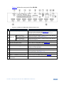
Figure 2 defines the rear panel of the VS-62H.
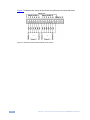
Figure 2: VS-62H 6x2 HDMI Matrix Switcher Rear Panel
#
1
Feature
REMOTE IR Opening
Function
Connect to an external IR receiver for controlling the device
via an IR remote controller (see Section 3.1).
Covered by a cap. The 3.5mm mini jack at the end of the internal IR
connection cable fits into this opening
2
3
REMOTE
INPUT To OUT 1
6-pin Terminal Block
Connect to up to six remote, contact-closure input selection
switches for Output 1 (see Section 6.3)
INPUT To OUT 2
7-pin Terminal Block
Connect to up to six remote, contact-closure input selection
switches for Output 2
4
RS-232 3-pin Terminal Block
Connect to a PC/serial controller (see Section 6.1)
5
SETUP 8-way DIP-switch
Sets the device configuration (see Section 9.1)
6
PROG VIA USB Connector
Connect to a PC to upgrade the firmware (see Section 9.3)
7
PROG VIA RS-232 Upgrade Switch
Depress to upgrade the firmware via the RS-232 port,
release for normal operation
8
ETHERNET RJ-45 Connector
Connect to a PC via a LAN (see Section 6.2)
9
RESET Switch
Press while power-cycling the device to reset to factory
default parameters (see Section 13)
10 5V DC Connector
Connect to the power adapter, center pin positive
11 INPUT 1~6 HDMI Input Connectors
Connect to up to six HDMI sources (see Section 6)
12 OUT 1 and OUT 2 HDMI Output
Connectors
Connect to up to two HDMI acceptors
VS-62H - Defining the VS-62H 6x2 HDMI Matrix Switcher
7
5
Installing in a Rack
This section provides instructions for rack mounting the unit.
8
VS-62H - Installing in a Rack
6
Connecting the VS-62H 6x2 HDMI Matrix
Switcher
i
Always switch off the power to each device before connecting it to your
VS-62H. After connecting your VS-62H, connect its power and then
switch on the power to each device.
Figure 3: Connecting the VS-62H 6x2 HDMI Matrix Switcher
To connect the VS-62H 6x2 HDMI Matrix Switcher as illustrated in the
example in Figure 3:
1. Connect up to six HDMI sources, (for example, Blu-ray Disc players) to the
HDMI Input connectors.
VS-62H - Connecting the VS-62H 6x2 HDMI Matrix Switcher
9
2. Connect the two OUT HDMI connectors to up to two HDMI acceptors, (for
example, LCD displays with built-in speakers).
3. If required, connect a PC/controller to the RS-232 port (see Section 6.1)
and/or the Ethernet port (see Section 6.2).
4. Connect the power adapter to the device and plug the power adapter into
the mains electricity (not shown in Figure 3).
5. If required, acquire the EDID (see Section 8.1).
6.1
Connecting a Serial Controller to the VS-62H via RS-232
To connect a serial controller to the VS-62H:
6.2
From the RS-232 9-pin D-sub serial port on the serial controller connect:
Pin 2 to the TX pin on the VS-62H RS-232 terminal block
Pin 3 to the RX pin on the VS-62H RS-232 terminal block
Pin 5 to the GND pin on the VS-62H RS-232 terminal block
Connecting to the VS-62H via Ethernet
You can connect to the VS-62H via Ethernet using either of the following methods:
Directly to the PC using a crossover cable (see Section 6.2.1)
Via a network hub, switch, or router, using a straight-through cable (see
Section 6.2.2)
Note: If you want to connect via a router and your IT system is based on IPv6,
speak to your IT department for specific installation instructions.
6.2.1
Connecting the Ethernet Port Directly to a PC
You can connect the Ethernet port of the VS-62H directly to the Ethernet port on
your PC using a crossover cable with RJ-45 connectors.
i
10
This type of connection is recommended for identifying the VS-62H
with the factory configured default IP address.
VS-62H - Connecting the VS-62H 6x2 HDMI Matrix Switcher
After connecting the VS-62H to the Ethernet port, configure your PC as
follows:
1. Click Start > Control Panel > Network and Sharing Center.
2. Click Change Adapter Settings.
3. Highlight the network adapter you want to use to connect to the device and
click Change settings of this connection.
The Local Area Connection Properties window for the selected network
adapter appears as shown in Figure 4.
Figure 4: Local Area Connection Properties Window
4. Highlight Internet Protocol Version 4 (TCP/IPv4) by clicking on the item.
5. Click Properties.
The Internet Protocol Properties window appears as shown in Figure 5.
VS-62H - Connecting the VS-62H 6x2 HDMI Matrix Switcher
11
Figure 5: Internet Protocol Version 4 Properties Window
6. Select Use the following IP Address for static IP addressing and fill in the
details as shown in Figure 6.
For TCP/IPv4 you can use any IP address in the range 192.168.1.1 to
192.168.1.255 (excluding 192.168.1.39) that is provided by your IT
department.
12
VS-62H - Connecting the VS-62H 6x2 HDMI Matrix Switcher
Figure 6: Internet Protocol Properties Window
7. Click OK.
8. Click Close.
6.2.2
Connecting the Ethernet Port via a Network Hub or Switch
You can connect the Ethernet port of the VS-62H to the Ethernet port on a network
hub or using a straight-through cable with RJ-45 connectors.
6.3
Connecting the Remote Contact-closure Switches
You can connect up to six remote, contact-closure switches per output to control
the VS-62H remotely. These switches replicate the Input selection buttons on the
front panel of the VS-62H.
VS-62H - Connecting the VS-62H 6x2 HDMI Matrix Switcher
13
Figure 7 illustrates the wiring of the switch connections to the terminal block.
Figure 7: Remote Contact-closure Switch Connections
14
VS-62H - Connecting the VS-62H 6x2 HDMI Matrix Switcher
7
Principles of Operation
This section describes the operating theory of the VS-62H and includes:
7.1
Automatic signal detection (see Section 7.1)
Input switching modes (see Section 7.2)
EDID operation (see Section 7.3)
Automatic Signal Detection
The VS-62H can automatically detect the presence of a video signal on an input
based on the presence of a video sync or clock signal.
7.2
Input Switching Modes
7.2.1
Manual Mode
In Manual switching mode, routing is performed according to the front panel button
selection or according to the remote command selection.
7.2.2
Automatic Mode
Automatic switching can be performed in either of the following ways:
Input priority. Upon detection of an active input, the input with the highest
priority is automatically selected. Input priority is from the lowest input
number (1) to the highest (6)
Last Connected. The device automatically selects the most recently
connected input. Should this source become inactive, the device
automatically switches to the last connected input that was active. When
turning the device on and more than one input is active, the input with the
highest priority is selected
If a manual selection is made when the device is in Automatic mode, the device
enters Manual Override mode. The manually selected input remains selected as
long as it is active. When a manually selected input becomes inactive, the device
returns to Automatic mode.
VS-62H - Principles of Operation
15
7.3
EDID Operation
The VS-62H has a default EDID (see Section 14) stored on all inputs. This EDID
can be exchanged for either:
A custom EDID which is uploaded to one or more inputs using Protocol 3000
commands (see Section 15.2)
–OR–
The EDID of a display device connected to an output by using either the
front panel buttons (see Section 8.2), a Protocol 3000 command, or the Web
pages
The EDID is non-volatile and the last valid EDID is used when the device is
powered up.
7.4
Step-in Functionality
The VS-62H can function as a step-in switcher when connected to a suitable
HDMI transmitter, (for example, the SID-X3N), using the correct HDMI cable with
HEC support.
Use the Web pages (see Section 10.2.2) to assign remote device button actions.
The default button actions are shown in the following table. Up to three buttons
can be active at the same time.
Command
16
Action
Echo
Allows a connected controller to be programmed to perform a variety
of tasks triggered by the user buttons, such as, room control, (lights,
screen, and so on)
Out1
Step in current input to Output 1
Out2
Step in current input to Output 2
VS-62H - Principles of Operation
8
Operating the VS-62H 6x2 HDMI Matrix
Switcher
This section describes operating the VS-62H and consists of:
8.1
Switching an input to an output (see Section 8.1)
Acquiring an EDID from an output (see Section 8.2)
Muting and unmuting the outputs (see Section 8.3)
Locking and unlocking the front panel buttons (see Section 8.4)
Generating a test pattern (see Section 8.5)
Switching an Input to an Output
To switch an input to an output, (for example, Input 5 to Output 2):
Press the Input 5 button in the bottom Output (To OUT 2) row.
The LED lights red and Input 5 is switched to Output 2
8.2
Acquiring an EDID from an Output
You can acquire the EDID from OUT 1 or OUT 2 and copy it to any or all of the six
inputs to be stored in non-volatile memory. You can also reset any or all of the
inputs to the default EDID.
To copy the EDID from an Output to one or more Inputs:
1. Press the EDID button to enter the EDID setting mode.
The EDID button lights.
Note: If there is no button activity for 10 seconds, the device automatically exits
the EDID setting mode to normal operation, the EDID button no longer lights and
any changes made are lost.
2. From the To OUT 1 (top) row, press each of the Inputs to which you want to
copy the EDID from Output 1.
Each selected Input LED lights.
VS-62H - Operating the VS-62H 6x2 HDMI Matrix Switcher
17
3. From the To OUT 2 (bottom) row, press each of the Inputs into which you
want to copy the EDID from Output 2.
Each selected Input LED lights.
4. Press the EDID button.
The button no longer lights and the EDID changes are saved.
To copy the default EDID to one or more Inputs:
1. Press the EDID button to enter the EDID setting mode.
The EDID button lights.
2. For each Input to which you want to copy the default EDID, press both the
To OUT 1 and To OUT 2 buttons simultaneously.
Both top row and bottom row Input LEDs light.
3. Press the EDID button.
The button no longer lights and the EDID changes are saved.
8.3
Muting and Unmuting the Outputs
To mute and unmute both outputs simultaneously:
1. Press the Mute button.
The Mute button lights and the outputs are muted.
2. Press the lit Mute button.
The outputs are unmuted and the button no longer lights.
To mute and unmute one output:
1. Press the currently selected (and lit) input button.
The output is muted and the button flashes.
2. Press the currently muted (and flashing) input button.
The output is unmuted and the button lights solid.
18
VS-62H - Operating the VS-62H 6x2 HDMI Matrix Switcher
8.4
Locking and Unlocking the Front Panel Buttons
To lock and unlock the front panel buttons:
1. Press and hold the Lock button.
The front panel buttons are locked and the button lights.
2. Press and hold the Lock button again.
The front panel buttons are unlocked and the button no longer lights.
8.5
Generating a Test Pattern
For diagnostic purposes, the VS-62H can generate a number of test patterns on
the outputs.
To generate a test pattern on the outputs:
1. Press the Function button.
The button lights.
2. Press any of the Input buttons to select a test pattern.
The selected test pattern is generated on the outputs.
To exit the test pattern generator:
Press the lit Function button.
The test pattern generation ceases and the button no longer lights.
Figure 8 shows the test patterns available.
VS-62H - Operating the VS-62H 6x2 HDMI Matrix Switcher
19
Figure 8: Available Test Patterns
20
VS-62H - Operating the VS-62H 6x2 HDMI Matrix Switcher
9
Configuring and Maintaining the VS-62H
This section describes the configuration and maintenance of the VS-62H and
consists of:
9.1
Setting the DIP-switches (see Section 9.1)
Resetting the device to factory default settings (see Section 9.2)
Upgrading the firmware (see Section 9.3)
Setting the DIP-switches
The DIP-switches dictate the behavior of the VS-62H.
All DIP-switches are off by default.
#
Feature
Description
1
HDCP support on inputs
On—Disable HDCP support on all inputs
Off—Enable HDCP support which is
defined by P3000 commands
2
Video mode switching Output 1
On—Auto
Off—Manual
3
Last connected/Priority mode Output 1
When DIP-switch 2 is set to Auto (ON):
On—Enable Last Connected mode
Off—Enable Priority mode where the
priority of each input is defined by the input
number, (1 is the highest priority)
4
Video mode switching Output 2
On—Auto
Off—Manual
5
Last connected/Priority mode Output 2
When DIP-switch 4 is set to Auto (ON):
On—Enable Last connected mode
Off—Enable Priority mode where the
priority of each input is defined by the input
number, (1 is the highest priority)
VS-62H - Configuring and Maintaining the VS-62H
21
9.2
Resetting the VS-62H to Factory Default Settings
To reset the device to factory default settings:
1. Power off the device.
2. Press and hold down the Reset button on the rear panel.
3. While holding down the Reset button, power on the device.
4. Wait a few seconds and release the button.
The device is reset to its factory settings.
9.3
Upgrading the Firmware
The VS-62H can be upgraded via any of the following:
Mini USB
RS-232
Ethernet
For instructions on upgrading the firmware see “K-Upload Software”.
22
VS-62H - Configuring and Maintaining the VS-62H
10
Operating the VS-62H Remotely via the Web
Pages
The VS-62H can be operated remotely using the embedded Web pages. The Web
pages are accessed using a Web browser and an Ethernet connection.
Before attempting to connect:
10.1
Perform the procedures in Section 6.2
Ensure that your browser is supported (see Section 12)
Ensure that JavaScript is enabled
Browsing the VS-62H Web Pages
Note: In the event that a Web page does not update correctly, clear your Web
browser’s cache (by pressing CTRL-F5).
To browse the VS-62H Web pages:
1. Open your Internet browser.
2. Type the IP number of the device (see Section 6.2) in the Address bar of
your browser.
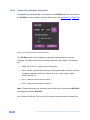
The Loading page appears.
Figure 9: The Loading Page
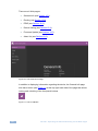
Immediately after the Loading page, the General Info page appears which displays
information related to the device and the Web page version.
VS-62H - Operating the VS-62H Remotely via the Web Pages
23
There are six Web pages:
General Info (see Section 10.1)
Routing (see Section 10.2)
EDID (see Section 10.3)
Device Setting (see Section 10.4)
Firmware Update (see Section 10.5)
About Us (see Section 10.6)
Figure 10: The General Info Page
In addition to displaying information regarding the device, the General Info page
also has a button (see Figure 11) at the top right hand side of the page that allows
locking and unlocking of the front panel buttons.
Figure 11: The Lock Button
24
VS-62H - Operating the VS-62H Remotely via the Web Pages
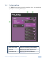
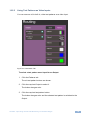
10.2
The Routing Page
The VS-62H Routing page lets you perform operational actions, such as, switching
inputs/outputs and selecting HDCP support.
Figure 12: The Routing Page
#
Item
Description
1
Output Buttons 1 and 2
2 Buttons for output selection, signal identification,
and audio and video muting (see Section 10.2.1)
2
Inputs Tab
6 Buttons for input selection, and port and signal
identification (see Section 10.2.1)
3
Patterns Button Tab
6 Buttons for video pattern generation (see
Section 10.2.3)
VS-62H - Operating the VS-62H Remotely via the Web Pages
25
Figure 13: The Output Buttons
#
26
Item
Description
1
Output Button Number
Identifies the Output number
2
HDCP Indicator
Indicates whether the Output port supports HDCP
3
Video Mute Button
Click the button to mute the video
4
Signal Indicator
Indicates whether or not there is a device connected
to the output
5
Mode Indicator
Indicates the switching mode currently employed
VS-62H - Operating the VS-62H Remotely via the Web Pages
Figure 14: The Input Buttons
#
Item
Description
1
Input Button Number
Identifies the Input number
2
Input Type and Signal
Indicator
Indicates the type of input and whether there is a
signal present on the Input
3
HDCP Selection Button
Click the button to turn HDCP support for the Input
on and off
4
HDCP Content Indicator
Indicates whether or not the Input signal is HDCP
protected
5
Remote Device Control
Button
Click the button to display the control window for the
remote device connected to this Input (see Section
10.2.2)
10.2.1
Switching an Input to an Output
To switch an Input to an Output, (for example, Input 2 to Output 2):
1. Click on Output button 2.
The button changes color to purple and the Output is selected.
2. Click on Input button 2.
The button changes color to purple and the output is switched.
VS-62H - Operating the VS-62H Remotely via the Web Pages
27
10.2.2
Controlling a Remote Transmitter
Compatible remote transmitters, (for example, the SID-X3N) that are connected to
the VS-62H can be controlled using the Web pages, (see Section 10.2, Figure 14).
Figure 15: The Remote Device Control Window
The VS-62H allows you to program the general purpose buttons on remote
modules. The table shows the functionality defined for each button. The options
are:
HDMI, DP, DVI, PC—selects one of the inputs
Echo—allows a connected controller to be programmed to perform a variety
of tasked triggered by the user buttons, such as, room control, (lights,
screen, and so on)
Out 1—step-in current input to output 1
Out 2—step-in current input to output 2
Note: These settings are per input and remain valid even if the remote SID-X3N is
exchanged for another SID-X3N.
Up to three of the Echo, Out 1 and Out 2 buttons can be active at the same time.
28
VS-62H - Operating the VS-62H Remotely via the Web Pages
10.2.3
Using Test Patterns as Video Inputs
You can use one of six built-in, video test patterns as a video Input.
Figure 16: Test Pattern Tab
To select a test pattern as an Input for an Output:
1. Click the Patterns tab.
The six test pattern buttons are shown.
2. Click the required Output to select it.
The button changes color.
3. Click the required test pattern button.
The button changes color and the selected test pattern is switched to the
Output.
VS-62H - Operating the VS-62H Remotely via the Web Pages
29
10.3
The EDID Page
The VS-62H EDID page lets you copy EDID data to one or more Inputs from an:
Output
Input
EDID data file
Figure 17: The EDID Page
Note: The display is not updated automatically when the status of an EDID
changes on the device due to outputs being exchanged. Click Refresh to update
the display.
30
VS-62H - Operating the VS-62H Remotely via the Web Pages
To copy EDID data from an Output or Input to one or more inputs:
1. Click the source button from which to copy the EDID (Output or Input).
The button changes color and the EDID summary information reflects the
EDID data.
2. Click one or more destination Inputs, or select all Inputs by checking the
Inputs check-box.
All selected Input buttons change color and the EDID summary information
reflects the Input selection(s).
3. Click the Copy button.
The “EDID was copied” success message is displayed and the EDID data
are copied to the selected Input(s).
4. Click OK.
To copy EDID data to an Input from an EDID data file:
1. Click the source Browse button.
The Windows Browser opens.
2. Browse to the required file.
3. Select the required file and click Open.
The EDID summary information reflects the selection.
4. Click one or more destination Inputs, or select all Inputs by checking the
Inputs check-box.
All selected Input buttons change color and the EDID summary information
reflects the Input selection(s).
5. Click the Copy button.
The “EDID was copied” success message is displayed and the EDID data
are copied to the selected Input(s).
6. Click OK.
VS-62H - Operating the VS-62H Remotely via the Web Pages
31
10.4
The Device Setting Page
The VS-62H Device Settings page lets you modify some communication
parameters and view others.
Figure 18: The Device Setting Page
To modify serial or Ethernet communication parameters:
1. Adjust the parameters as required, either by entering the parameters directly
or by using the drop-down list.
2. Click Set.
The changes are saved.
32
VS-62H - Operating the VS-62H Remotely via the Web Pages
10.5
The Firmware Upgrade Page
The Firmware Upgrade page lets you perform a firmware upgrade from a firmware
file.
Figure 19: The Firmware Upgrade Page
To upgrade the firmware:
1. Click the Choose File button.
The Windows Browser opens.
2. Browse to the required file.
3. Select the required file and click Open.
The firmware file name is displayed in the Firmware Upgrade page.
4. Click Start Upgrade.
The firmware file is loaded and a progress bar is displayed.
!
Do not interrupt the process or the VS-62H may be damaged.
5. When the process is complete reboot the device.
The firmware is upgraded.
VS-62H - Operating the VS-62H Remotely via the Web Pages
33
10.6
The About Us Page
The VS-62H About Us page displays the Web page version and Kramer
Electronics Ltd company details.
Figure 20: The About Us Page
34
VS-62H - Operating the VS-62H Remotely via the Web Pages
11
Wiring the Twisted Pair RJ-45 Connectors
Connect/solder the cable shield to the RJ-45 connector shield.
!
Do not use a crossed TP cable with this product.
Using a TP cable that is incorrectly wired may cause permanent
damage to the device
Do not use unshielded TP cables with this product
Figure 21 defines the TP pinout using a straight pin-to-pin cable with RJ-45
connectors.
EIA /TIA 568B
PIN
1
Orange / White
2
Orange
3
Green / White
4
Blue
5
Blue / White
6
Green
7
Brown / White
8
Brown
Pair 1
4 and 5
Pair 2
1 and 2
Pair 3
3 and 6
Pair 4
7 and 8
Figure 21: TP Pinout Wiring
Wire Color
VS-62H - Wiring the Twisted Pair RJ-45 Connectors
35
12
Technical Specifications
INPUTS:
6 HDMI Connectors
OUTPUTS:
2 HDMI Connectors
PORTS:
1 Ethernet on an RJ-45 connector
1 IR on a 3.5mm mini jack
12 Remote selection contact-closure switches on 13 terminal
block pins
1 Serial port on a 3-pin terminal block
1 Program port on a mini USB
BANDWIDTH:
Up to 8.91Gbps data rate (2.97Gbps per graphic channel)
COMPLIANCE WITH
HDMI STANDARD:
HDMI and HDCP
RESOLUTION:
Up to UXGA; 4K x 2K
SUPPORTED BAUD
RATES:
9600, 115200bps
SUPPORTED WEB
BROWSERS:
The following operating systems and Web browsers are
supported:
Windows 7:
◦
Google Chrome v25
◦
FireFox v15
◦
Opera v12
◦
Microsoft Internet Explorer v9
Windows XP:
◦
Google Chrome v25
◦
FireFox v15
Apple Mac:
◦
Google Chrome v25
◦
FireFox v20
◦
Opera v12.14
◦
Safari v6
POWER
CONSUMPTION:
5V DC 880mA
CONTROLS:
Front panel buttons, infrared remote control transmitter, RS-232,
Ethernet, Remote input selection switches
OPERATING
TEMPERATURE:
0° to +40°C (32° to 104°F)
STORAGE
TEMPERATURE:
–40° to +70°C (–40° to 158°F)
HUMIDITY:
10% to 90%, RHL non-condensing
DIMENSIONS:
21.5cm x 16.6cm x 4.4cm (8.46" x 6.54" x 1.73") W, D, H
WEIGHT:
1.0kg (2.2lbs) approx.
INCLUDED
ACCESSORIES:
Power adapter, IR transmitter
OPTIONS:
External remote IR receiver cable, RK-3TR
Specifications are subject to change without notice at http://www.kramerelectronics.com
36
VS-62H - Technical Specifications
13
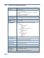
Default Communication Parameters
RS-232
Protocol 3000
Baud Rate:
115,200
Data Bits:
8
Stop Bits:
1
Parity:
None
Command Format:
ASCII
TCP/IP Parameters
IP Address:
192.168.1.39
Netmask:
255.255.0.0
Gateway:
0.0.0.0
TCP Port #:
5000
UDP Port #:
50000
VS-62H - Default Communication Parameters
37
14
Default EDID
Monitor
Model name............... VS-62H
Manufacturer............. KMR
Plug and Play ID......... KMR0200
Serial number............ 1
Manufacture date......... 2010, ISO week 24
Filter driver............ None
------------------------EDID revision............ 1.3
Input signal type........ Digital (DVI)
Color bit depth.......... Undefined
Display type............. RGB color
Screen size.............. 700 x 390 mm (31.5 in)
Power management......... Not supported
Extension blocs.......... 1 (CEA-EXT)
------------------------DDC/CI................... n/a
Color characteristics
Default color space...... Non-sRGB
Display gamma............ 2.20
Red chromaticity......... Rx 0.640 - Ry 0.341
Green chromaticity....... Gx 0.286 - Gy 0.610
Blue chromaticity........ Bx 0.146 - By 0.069
White point (default).... Wx 0.284 - Wy 0.293
Additional descriptors... None
Timing characteristics
Horizontal scan range.... 31-94kHz
Vertical scan range...... 50-85Hz
Video bandwidth.......... 170MHz
CVT standard............. Not supported
GTF standard............. Not supported
Additional descriptors... None
Preferred timing......... Yes
Native/preferred timing.. 1280x720p at 60Hz
Modeline............... "1280x720" 74.250 1280 1390 1430 1650 720 725 730 746 +hsync -vsync
Detailed timing #1....... 1920x1080p at 60Hz (16:9)
Modeline............... "1920x1080" 148.500 1920 2008 2052 2200 1080 1084 1089 1125 +hsync +vsync
Standard timings supported
720 x 400p at 70Hz - IBM VGA
720 x 400p at 88Hz - IBM XGA2
640 x 480p at 60Hz - IBM VGA
640 x 480p at 67Hz - Apple Mac II
640 x 480p at 72Hz - VESA
640 x 480p at 75Hz - VESA
800 x 600p at 56Hz - VESA
800 x 600p at 60Hz - VESA
800 x 600p at 72Hz - VESA
800 x 600p at 75Hz - VESA
832 x 624p at 75Hz - Apple Mac II
1024 x 768i at 87Hz - IBM
1024 x 768p at 60Hz - VESA
1024 x 768p at 70Hz - VESA
1024 x 768p at 75Hz - VESA
1280 x 1024p at 75Hz - VESA
1152 x 870p at 75Hz - Apple Mac II
1280 x 720p at 60Hz - VESA STD
1280 x 800p at 60Hz - VESA STD
1440 x 900p at 60Hz - VESA STD
1280 x 960p at 60Hz - VESA STD
1280 x 1024p at 60Hz - VESA STD
1400 x 1050p at 60Hz - VESA STD
1680 x 1050p at 60Hz - VESA STD
1600 x 1200p at 60Hz - VESA STD
EIA/CEA-861 Information
Revision number.......... 3
IT underscan............. Not supported
Basic audio.............. Supported
YCbCr 4:4:4.............. Supported
YCbCr 4:2:2.............. Supported
Native formats........... 1
38
VS-62H - Default EDID
Detailed timing #1....... 720x480p at 60Hz (4:3)
Modeline............... "720x480" 27.000 720 736 798 858 480 489 495 525 -hsync -vsync
Detailed timing #2....... 1920x1080i at 60Hz (16:9)
Modeline............... "1920x1080" 74.250 1920 2008 2052 2200 1080 1084 1094 1124 interlace +hsync +vsync
Detailed timing #3....... 1920x1080i at 50Hz (16:9)
Modeline............... "1920x1080" 74.250 1920 2448 2492 2640 1080 1084 1094 1124 interlace +hsync +vsync
Detailed timing #4....... 1280x720p at 60Hz (16:9)
Modeline............... "1280x720" 74.250 1280 1390 1430 1650 720 725 730 750 +hsync +vsync
Detailed timing #5....... 1280x720p at 50Hz (16:9)
Modeline............... "1280x720" 74.250 1280 1720 1760 1980 720 725 730 750 +hsync +vsync
CE video identifiers (VICs) - timing/formats supported
720 x 576p at 50Hz - EDTV (4:3, 16:15)
1280 x 720p at 50Hz - HDTV (16:9, 1:1)
1920 x 1080i at 60Hz - HDTV (16:9, 1:1)
1920 x 1080i at 50Hz - HDTV (16:9, 1:1)
1280 x 720p at 60Hz - HDTV (16:9, 1:1) [Native]
1920 x 1080p at 60Hz - HDTV (16:9, 1:1)
1920 x 1080p at 50Hz - HDTV (16:9, 1:1)
NB: NTSC refresh rate = (Hz*1000)/1001
CE audio data (formats supported)
LPCM 3-channel, 24-bits
at 44/48 kHz
CE speaker allocation data
Channel configuration.... 3.0
Front left/right......... Yes
Front LFE................ No
Front center............. Yes
Rear left/right.......... No
Rear center.............. No
Front left/right center.. No
Rear left/right center... No
Rear LFE................. No
CE vendor specific data (VSDB)
IEEE registration number. 0x000C03
CEC physical address..... 1.0.0.0
Maximum TMDS clock....... 165MHz
Raw data
00,FF,FF,FF,FF,FF,FF,00,2E,4D,00,02,01,00,00,00,18,14,01,03,81,46,27,78,0A,D5,7C,A3,57,49,9C,25,
11,48,4B,FF,FF,80,81,C0,81,00,95,00,81,40,81,80,90,40,B3,00,A9,40,01,1D,00,72,51,D0,1A,20,6E,28,
55,00,7E,88,42,00,00,1A,02,3A,80,18,71,38,2D,40,58,2C,45,00,C4,8E,21,00,00,1E,00,00,00,FC,00,56,
53,2D,34,32,48,4E,0A,20,20,00,00,00,00,00,00,FD,00,32,55,1F,5E,11,00,0A,20,20,20,20,20,20,01,7B,
02,03,1A,71,47,11,13,05,14,84,10,1F,23,0A,06,04,83,05,00,00,65,03,0C,00,10,00,8C,0A,D0,8A,20,E0,
2D,10,10,3E,96,00,58,C2,21,00,00,18,01,1D,80,18,71,1C,16,20,58,2C,25,00,C4,8E,21,00,00,9E,01,1D,
80,D0,72,1C,16,20,10,2C,25,80,C4,8E,21,00,00,9E,01,1D,00,72,51,D0,1E,20,6E,28,55,00,C4,8E,21,00,
00,1E,01,1D,00,BC,52,D0,1E,20,B8,28,55,40,C4,8E,21,00,00,1E,00,00,00,00,00,00,00,00,00,00,00,90
VS-62H - Default EDID
39
15
Protocol 3000
The VS-62H can be operated using serial commands from a PC, remote controller
or touch screen using the Kramer Protocol 3000.
This section describes:
15.1
Kramer Protocol 3000 syntax (see Section 15.1)
Kramer Protocol 3000 commands (see Section 15.2)
Kramer Protocol 3000 Syntax
15.1.1
Host Message Format
Start
Address (optional)
Body
Delimiter
#
Destination_id@
Message
CR
15.1.1.1
Simple Command
Command string with only one command without addressing:
Start
Body
Delimiter
#
Command SP Parameter_1,Parameter_2,…
CR
15.1.1.2
Command String
Formal syntax with commands concatenation and addressing:
Start
Address
Body
Delimiter
#
Destination_id@
Command_1 Parameter1_1,Parameter1_2,…|
Command_2 Parameter2_1,Parameter2_2,…|
Command_3
Parameter3_1,Parameter3_2,…|…
CR
15.1.2
Device Message Format
Start
Address (optional)
Body
delimiter
~
Sender_id@
Message
CR LF
15.1.2.1
Device Long Response
Echoing command:
Start
Address (optional)
Body
Delimiter
~
Sender_id@
Command SP [Param1 ,Param2 …] result
CR LF
CR = Carriage return (ASCII 13 = 0x0D)
LF = Line feed (ASCII 10 = 0x0A)
SP = Space (ASCII 32 = 0x20)
40
VS-62H - Protocol 3000
15.1.3
Command Terms
Command
A sequence of ASCII letters ('A'-'Z', 'a'-'z' and '-').
Command and parameters must be separated by at least one space.
Parameters
A sequence of alphanumeric ASCII characters ('0'-'9','A'-'Z','a'-'z' and some special
characters for specific commands). Parameters are separated by commas.
Message string
Every command entered as part of a message string begins with a message
starting character and ends with a message closing character.
Note: A string can contain more than one command. Commands are separated by
a pipe ( '|' ) character.
Message starting character
'#' – For host command/query
'~' – For device response
Device address (Optional, for K-NET)
K-NET Device ID followed by '@'
Query sign
'?' follows some commands to define a query request.
Message closing character
CR – For host messages; carriage return (ASCII 13)
CRLF – For device messages; carriage return (ASCII 13) + line-feed (ASCII 10)
Command chain separator character
When a message string contains more than one command, a pipe ( '|' ) character
separates each command.
Spaces between parameters or command terms are ignored.
VS-62H - Protocol 3000
41
15.1.4
Entering Commands
You can directly enter all commands using a terminal with ASCII communications
software, such as HyperTerminal, Hercules, etc. Connect the terminal to the serial
or Ethernet port on the Kramer device. To enter CR press the Enter key.
( LF is also sent but is ignored by command parser).
For commands sent from some non-Kramer controllers, (for example, Crestron)
some characters require special coding (such as, /X##). Refer to the controller
manual.
15.1.5
Command Forms
Some commands have short name syntax in addition to long name syntax to allow
faster typing. The response is always in long syntax.
15.1.6
Chaining Commands
Multiple commands can be chained in the same string. Each command is
delimited by a pipe character (“|”). When chaining commands, enter the message
starting character and the message closing character only once, at the
beginning of the string and at the end.
Commands in the string do not execute until the closing character is entered. A
separate response is sent for every command in the chain.
15.1.7
Maximum String Length
64 characters
42
VS-62H - Protocol 3000
15.2
Kramer Protocol 3000 Commands
The following table lists the Protocol 3000 commands that the VS-62H supports.
For a full description of the commands, see the Kramer Protocol 3000 document
available from http://www.kramerelectronics.com.
Command
Description
#
Protocol handshaking
AUD
Switch Audio only
AUD-EMB?
Get audio-in-video embedding status
BUILD-DATE?
Read device build date
CPEDID
Copy EDID data from the output to the input EEPROM
DEF-RES
Assign custom defined scaled video output resolution to “vic” index
DEF-RES?
Get custom defined video resolution
DISPLAY
Valid / Invalid output
DISPLAY?
Get output HPD status
ETH-PORT
Change protocol Ethernet port
ETH-PORT?
Get protocol Ethernet port
FACTORY
Reset to factory default configuration
HDCP-MOD
Set HDCP mode
HDCP-MOD?
Get HDCP mode?
HDCP-STAT?
Get HDCP signal status
HELP
List of commands
LOCK-FP
Lock front panel
LOCK-FP?
Get status of front panel lock
MODEL?
Read device model
MTX-MODE?
Get switch mode
NAME
Set machine (DNS) name
NAME?
Get machine (DNS) name
NAME-RST
Reset machine name to factory default (DNS)
NET-DHCP
Set DHCP mode
NET-DHCP?
Get DHCP mode
NET-GATE
Set Gateway
NET-GATE?
Get Gateway
NET-IP
Set IP address
NET-IP?
Get IP address
NET-MAC?
Read MAC address
NET-MASK
Set subnet mask
NET-MASK?
Get subnet mask
PRIO?
Get input priority
PROTOCOL START
Change description in documentation
PROT-VER?
Read device protocol version
VS-62H - Protocol 3000
43
Command
RESET
Description
Reset device
ROUTE
Set layer routing
ROUTE?
Get layer routing
SIGNAL
Valid / Invalid input
SIGNAL?
Get input signal lock status
SN?
Read device serial number
STX
Switch Serial TX data channel connection
VERSION?
Read device firmware version
VID
set video switch status
VID?
Get video switch status
VID-PATTERN
Sets video test pattern
VID-PATTERN?
Gets video test pattern
VMUTE
Set enable/ disable video on output
VMUTE?
Get video on output status
44
VS-62H - Protocol 3000
For the latest information on our products and a list of Kramer distributors,
visit our Web site where updates to this user manual may be found.
We welcome your questions, comments, and feedback.
Web site: www.kramerelectronics.com
E-mail: [email protected]
!
SAFETY WARNING
Disconnect the unit from the power
supply before opening and servicing
P/N: 2900- 300170
Rev: 1