1
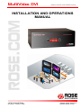
MultiVideo DVI Matrix Switch with RS232 Control INSTALLATION AND OPERATIONS MANUAL 10707 Stancliff Road Houston, Texas 77099 Phone: (281) 933-7673 WWW.ROSE.COM LIMITED WARRANTY Rose Electronics® warrants the MultiVideo DVI to be in good working order for one year from the date of purchase from Rose Electronics or an authorized dealer. Should this product fail to be in good working order at any time during this one-year warranty period, Rose Electronics will, at its option, repair or replace the Unit as set forth below. Repair parts and replacement units will be either reconditioned or new. All replaced parts become the property of Rose Electronics. This limited warranty does not include service to repair damage to the Unit resulting from accident, disaster, abuse, or unauthorized modification of the Unit, including static discharge and power surges. Limited Warranty service may be obtained by delivering this unit during the one-year warranty period to Rose Electronics or an authorized repair center providing a proof of purchase date. If this Unit is delivered by mail, you agree to insure the Unit or assume the risk of loss or damage in transit, to prepay shipping charges to the warranty service location, and to use the original shipping container or its equivalent. You must call for a return authorization number first. Under no circumstances will a unit be accepted without a return authorization number. Contact an authorized repair center or Rose Electronics for further information. ALL EXPRESS AND IMPLIED WARRANTIES FOR THIS PRODUCT INCLUDING THE WARRANTIES OF MERCHANTABILITY AND FITNESS FOR A PARTICULAR PURPOSE, ARE LIMITED IN DURATION TO A PERIOD OF ONE YEAR FROM THE DATE OF PURCHASE, AND NO WARRANTIES, WHETHER EXPRESS OR IMPLIED, WILL APPLY AFTER THIS PERIOD. SOME STATES DO NOT ALLOW LIMITATIONS ON HOW LONG AN IMPLIED WARRANTY LASTS, SO THE ABOVE LIMITATION MAY NOT APPLY TO YOU. IF THIS PRODUCT IS NOT IN GOOD WORKING ORDER AS WARRANTED ABOVE, YOUR SOLE REMEDY SHALL BE REPLACEMENT OR REPAIR AS PROVIDED ABOVE. IN NO EVENT WILL ROSE ELECTRONICS BE LIABLE TO YOU FOR ANY DAMAGES INCLUDING ANY LOST PROFITS, LOST SAVINGS OR OTHER INCIDENTAL OR CONSEQUENTIAL DAMAGES ARISING OUT OF THE USE OF OR THE INABILITY TO USE SUCH PRODUCT, EVEN IF ROSE ELECTRONICS OR AN AUTHORIZED DEALER HAS BEEN ADVISED OF THE POSSIBILITY OF SUCH DAMAGES, OR FOR ANY CLAIM BY ANY OTHER PARTY. SOME STATES DO NOT ALLOW THE EXCLUSION OR LIMITATION OF INCIDENTAL OR CONSEQUENTIAL DAMAGES FOR CONSUMER PRODUCTS, SO THE ABOVE MAY NOT APPLY TO YOU. THIS WARRANTY GIVES YOU SPECIFIC LEGAL RIGHTS AND YOU MAY ALSO HAVE OTHER RIGHTS WHICH MAY VARY FROM STATE TO STATE. NOTE: This equipment has been tested and found to comply with the limits for a Class A digital device, pursuant to Part 15 of the FCC Rules. These limits are designed to provide reasonable protection against harmful interference when the equipment is operated in a commercial environment. This equipment generates, uses, and can radiate radio frequency energy and, if not installed and used in accordance with the instruction manual, may cause harmful interference to radio communications. Operation of this equipment in a residential area is likely to cause harmful interference in which case the user will be required to correct the interference at his own expense. IBM, AT, and PS/2 are trademarks of International Business Machines Corp. Microsoft and Microsoft Windows are registered trademarks of Microsoft Corp. Any other trademarks mentioned in this manual are acknowledged to be the property of the trademark owner. Copyright Rose Electronics 2009. All rights reserved. No part of this manual may be reproduced, stored in a retrieval system, or transcribed in any form or any means, electronic or mechanical, including photocopying and recording, without the prior written permission of Rose Electronics. Rose Electronics Part # MAN-MVDVI Printed In the United States of America – DECLARATION of CONFORMITY DECLARATION OF CONFORMITY ACCORDING TO COUNCIL DIRECTIVE 93/68/EEC Electromagnetic Compatibility Directive 89/336/EEC This equipment is in conformity with the protection requirements of the following Council Directives: The Declaration of Conformity is based upon compliance of the product with the following harmonized standards: EN55022: Radio Frequency Energy All interface cables used with this equipment must be shielded in order to maintain compliance with radio frequency energy emission regulations and ensure a suitably high level of immunity to electromagnetic disturbances. European EMC directive 89/336/EEC This equipment has been tested and found to comply with the limits for a class A computing device in accordance with the specifications in the European standard EN55022. These limits are designed to provide reasonable protection against harmful interference. This equipment generates, uses and can radiate radio frequency energy and if not installed and used in accordance with the instructions may cause harmful interference to radio or television reception. However, there is no guarantee that harmful interference will not occur in a particular installation. If this equipment does cause interference to radio or television reception, which can be determined by turning the equipment on and off, the user is encouraged to correct the interference with one or more of the following measures: (a) Reorient or relocate the receiving antenna. (b ) Increase the separation between the equipment and the receiver. (c) Connect the equipment to an outlet on a circuit different from that to which the receiver is connected. (d) Consult the supplier or an experienced radio/TV technician for help. FCC Compliance Statement (United States) This equipment generates, uses, and can radiate radio frequency energy and if not installed and used properly, that is, in strict accordance with the manufacturer’s instructions, may cause interference to radio communication. It has been tested and found to comply with the limits for a class A computing device in accordance with the specifications in Subpart J of part 15 of FCC rules, which are designed to provide reasonable protection against such interference when the equipment is operated in a commercial environment. Operation of this equipment in a residential area may cause interference, in which case the user, at his own expense, will be required to take whatever measures may be necessary to correct the interference. Changes or modifications not expressly approved by the manufacturer could void the user’s authority to operate the equipment. Canadian Department of Communications RFI statement This equipment does not exceed the class A limits for radio noise emissions from digital apparatus set out in the radio interference regulations of the Canadian Department of Communications. Le présent appareil numérique n’émet pas de bruits radioélectriques dépassant les limites applicables aux appareils numériques de la classe A prescrites dans le règlement sur le brouillage radioélectriques publié par le ministère des Communications du Canada. TABLE of CONTENTS Contents Page # Disclaimer .................................................................................................................................1 System Introduction...................................................................................................................1 Features ...............................................................................................................................1 Models ......................................................................................................................................2 Rear View .............................................................................................................................2 Front View ............................................................................................................................3 Installation.................................................................................................................................4 1- User Console Connections ...............................................................................................4 2- Connecting the USB peripherals to the unit.......................................................................4 3- Connecting the Computers to the unit ...............................................................................5 4- Applying power .................................................................................................................5 System Operation......................................................................................................................6 Selecting / switching to a computer .......................................................................................6 1- Front panel controls......................................................................................................6 2- HotKey switching..........................................................................................................7 3- Using mouse button presses to select a computer channel ..........................................7 4- Serial command to the “Option” port .............................................................................8 Configuration mode...............................................................................................................9 Managing EDID video display information ......................................................................10 Auto scanning.................................................................................................................11 Installing / synchronizing multiple units ....................................................................................11 Service ....................................................................................................................................12 Technical Support ...................................................................................................................12 Safety......................................................................................................................................13 Figures Page # Figure 1. Front panel controls....................................................................................................6 Tables Page # Table 1. Serial Cable................................................................................................................8 Table 2. Configuration menu options .......................................................................................10 Appendices Page # Appendix A – Specifications ....................................................................................................14 Appendix B – Default Video Modes .........................................................................................15 Appendix C – Synchronizing multiple units ..............................................................................15 INTRODUCTION Disclaimer While every precaution has been taken in the preparation of this manual, the manufacturer assumes no responsibility for errors or omissions. Neither does the manufacturer assume any liability for damages resulting from the use of the information contained herein. The manufacturer reserves the right to change the specifications, functions, or circuitry of the product without notice. The manufacturer cannot accept liability for damages due to misuse of the product or other circumstances outside the manufacturer’s control. The manufacturer will not be responsible for any loss, damage, or injury arising directly or indirectly from the use of this product. System Introduction Thank you for choosing Rose Electronics® MultiVideo DVI for your DVI video distribution applications. The MultiVideo DVI features full dual link DVI video or high definition analogue video. The advanced emulation technology of the MultiVideo DVI allows USB HID devices to be truly emulated to each computer, even specialty keyboards and mice. This technology enables instantaneous and reliable hotkey switching. The MultiVideo DVI also features two independent switchable USB 2.0 ports and an audio port. These ports can be switched to different computers. Switching is accomplished using local keyboard hotkey sequences, the front panel controls, or using a 3 button mouse. With these switching options you can quickly reassign the connected peripherals to any of the connected computers. Models are available supporting dual, tri or quad head DVI or VGA computers. Features Full dual link DVI video support Available models: 1x4 dual-link Dual, Tri, or Quad DVI-I video Resolutions up to 2560 x 1600 Select a computer using the front panel switches, hotkeys, or the mouse buttons Switch dual link digital video up to 300 Mpixels/sec Front panel indicator shows the currently active channel, which peripherals are switched to the active channel, keyboard and mouse activity, and power Digital or analogue video support (Analogue requires a converter) Supports a wide range of USB 2.0 peripherals (HID and Transparent devices) RS232 serial port for upgrades to the units firmware, synchronizing MultiVideo DVI units so multiple computers/video screens can be switched and accessed Remote serial port switching Flash upgradeable Installation and Operations Manual 1 MODELS Models The MultiVideo DVI is available in 3 different configurations. All models operate the same and computers and peripherals are switched in the same manor. Rear View 1x4 (dual, tri, quad) Computer Connections: Video – DVI-I Dual-Link USB 2.0 – Type B Audio - 3.5mm stereo jack 2 Installation and Operations Manual Front View LED display Peripherals switched to selected computer Select Peripherals (KVM, SPK, USB1 / 2) Select computer (1-4) Selected Computer V1-V4 video monitors switched to selected computer The front panel display indicates which computer port is selected and which peripherals (KVM, Speakers, USB1 or USB2) are switched to the current computer. The two push buttons (Computer and Mode) are used to switch to a computer (Computer) and select which peripherals (Mode) to switch to the selected computer. There are 6 different mode configurations to choose from. Each time the mode button is pressed a different combination of peripherals to switch is selected. The below table shows the different combinations. Installation and Operations Manual 3 INSTALLATION Installation Installation of the MultiVideo DVI unit consists of: 1. Connecting the User console equipment to the unit 2. Connecting the USB peripherals to the unit 3. Connecting the Computers to the unit 4. Applying power to all equipment The following installation instructions are a guide to properly connecting all of the equipment to the MultiVideo DVI unit. No special order is required but it is recommended that power to the equipment and to the MultiVideo DVI unit be applied after all connections have been made. 1- User Console Connections User Console Connections Connect a set of stereo speakers to the audio input jack if needed Connect the USB keyboard and USB mouse to the corresponding USB ports on the rear panel. Up to 4 video monitors with DVI-I or DVI-D connectors can be connected to the DVI-I female connectors on the rear panel. If you need to extend the monitors past the 16’ max DVI cable length, Rose Electronics’ CrystalView DVI CATx or Fiber products can extend the distance up to 450’ over CATx cable or up to 33,000’ over fiber cabling. 2- Connecting the USB peripherals to the unit USB Peripheral Connections Connect up to 2 supported USB peripherals to the USB 2.0 switched ports labeled USB 1 and USB 2. These USB ports provide enumerated (transparent) switching 4 Installation and Operations Manual 3- Connecting the Computers to the unit Up to 4 quad head computers can be connected to the MultiVideo DVI unit. Connect each computer’s DVI video output to the corresponding DVI-I connector on the MultiVideo DVI rear panel using a DVI-I or DVI-D MM video cables. Multi-head video outputs connect vertically to the V1, V2, V3, and V4 DVI connectors. Using a USB type A/B cable, connect each USB type B port on the MultiVideo DVI unit to the corresponding USB type A connector on each computer. A stereo 3.5mm audio cable is used to connect each computer’s audio output to the audio input port on the MultiVideo DVI unit’s rear panel. 4- Applying power Each unit is supplied with a 110-240 VAC 50/60Hz power adapter that supplies a +5 VDC, 4A, 20 watts to the MultiVideo DVI unit. There is no on/off power switch on the unit. Operation begins as soon as power is supplied to the unit. 1- Connect the power adapter output connector to the +5V power jack on the rear panel of the unit. 2- Connect the power cable to the IEC connector on the power adapter. 3- Connect the power cable to the main power supply source Both the power adapter and the unit generate heat when in operation. Please provide adequate air circulation to assure the ambient temperature does not exceed 104ºF (40º C). Installation and Operations Manual 5 OPERATION System Operation Selecting / switching to a computer There are four ways to switch to a computer: 1- Using the front panel controls 2- Using hotkeys 3- Using mouse button presses 4- Serial command to the “Option” port 1- Front panel controls The front panel controls (Figure 1) consist of two buttons, “Computer” and “Mode”, and a LED display showing which peripherals are connected to the selected computer (top indicator row), and which video monitors are switched to the selected computer (bottom indicator row). To select a given computer and switch the computer’s DVI videos to the display monitors, press the “Computer” button. Each time the “Computer” button is press the unit sequences to the next sequential computer number and the videos from that computer are displayed on the user console monitors. Figure 1. Front panel controls The “Mode” button shows / selects which peripherals are connected to the selected computer. Each time the mode button is pressed, different peripherals are selected to switch to the selected computer. The table below shows the peripheral selections available. Example: Switch USB2 only to computer #2 Press the “Computer” button until “2” displays (Computer #2 selected) Press the “Mode” button until an indicator displays just under USB2 and no other indicators are displayed. Press “Computer” to assign USB2 to computer #2. NOTE: If an indicator flashes, the selected peripheral is currently switched to another computer channel. 6 Installation and Operations Manual 2- HotKey switching The User Console USB keyboard can be used to issue Hotkey commands to the MultiVideo DVI unit. These hotkey commands can quickly switch the keyboard, monitor(s), mouse, speakers, and the USB peripherals to any computer channel. The default hotkey is the Ctrl + Alt key pressed simultaneously. If the default hotkey setting conflicts with other software or hardware, it can be easily changed to one of seven choices or the hotkey switching can be disabled. (See the Configuration Mode section for information on changing the hotkey) To switch to a given channel, press and hold the Ctrl and Alt key, then press the channel number. Ctrl + Alt + 1 Ctrl + Alt + 2 Ctrl + Alt + 3 Ctrl + Alt + 4 Ctrl + Alt + 0 Ctrl + Alt + Tab Selects channel 1 Selects channel 2 Selects channel 3 Selects channel 4 Disconnects/ isolates the user console from all channels Selects the next channel (See note) Note: The next channel that is selected when you press the Ctrl + Alt + Tab depends upon the setting that has been entered in the configuration mode; all or active ports. To switch selective peripherals to a given channel: 1- Press and hold Ctrl and Alt key 2- Press and release the command key [A] switch all peripherals [K] switch only the keyboard, monitor, and mouse [S] switch only the speakers [U] switch only USB1 and USB2 3- Press and release the channel number 1-4 to switch the peripheral choice to 4- Release the Ctrl and Alt keys Example: To switch all peripherals to channel 2, press and hold the Ctrl and Alt keys, press and release the A key, press and release the 2 key, release the Ctrl and Alt keys. Note: When entering numeric values, use the numeric keys above the keyboard to enter the values. Do not use the keypad to enter numbers. 3- Using mouse button presses to select a computer channel To select a computer channel using the mouse buttons; 1- Press and hold down the middle scroll wheel button 2- Click the left mouse button to increment the channel number or Click the right mouse button to decrement the channel number When the correct channel is reached, release the middle scroll wheel button The next channel that is selected when you press the left or right mouse button depends upon the setting that has been entered in the configuration mode; all or active ports. The peripherals switched using the mouse switch method depends upon the switching mode currently set using the front panel button. Installation and Operations Manual 7 4- Serial command to the “Option” port To switch channels using serial commands to the “Option” port, connect a serial cable from a computer’s serial port to the “Option” port on the MultiVideo DVI unit. The serial cable is usually an 8p8c connector on one end and a DB9F connector on the other end. The “Option” port on the MultiVideo DVI uses a 10p10c socket. This socket will accommodate a 10p10c and an 8p8c connector. Serial cable pin-out Set the serial port parameters to: Baud rate – 1200 Data bits – 8 Stop bits – 1 Parity - None Table 1. Serial Cable With the proper serial cable connected from a computer and the MultiVideo DVI, start your computer’s serial communication program (HyperTerminal, TeraTerm, etc). Set the serial port parameters as designated in Table 1. To select a channel, enter the below code. If entering ASCII characters from an attached computer’s keyboard, use the numeric keys above the keyboard, not the keypad. Select channel 1: Select channel 2: Select channel 3: Select channel 4: 8 ASCII Character 1 2 3 4 Hex 0x31 0x32 0x33 0x34 Decimal 49 50 51 52 Installation and Operations Manual Configuration mode When you enter the configuration mode, each menu mode offers several settings that can be used to customize the actions of the MultiVideo DVI unit. To enter the configuration mode, press and hold the front panel “Computer” button for approximately five (5) seconds. 1. After 5 seconds, the display will show a bracket symbol ‘ [ ‘ 2. Using the user console keyboard enter the Menu Mode Selection Letter: The display will show the selected letter. (e.g. H) (See table 2) 3. Enter the required Mode Selection Number: The display will show the selected number (e.g. 6) 4. Press Enter on the keyboard to accept the setting and return to the main menu section. The display will show the bracket symbol “[ “ 5. Return to step 2 to make another configuration change or Press the “E” key and then press Enter to exit and save the changes. Menu Mode Selection Letter / Number Description Functions Menu (System Functions) F 1 Enter Show current firmware version F 2 Enter Refresh EDID information from the connected video display F 8 Enter Reset configuration to factory defaults Hotkey Menu H 1 Enter H 2 Enter H 3 Enter H 4 Enter H 5 Enter H 6 Enter H 7 Enter H 8 Enter (Change hotkey from default setting to) Ctrl + Alt (Default setting) Ctrl + Shift Alt + Shift Right Alt Alt Left Ctrl + Alt Right Ctrl + Alt Disable hotkeys Switch Menu S 1 Enter S 2 Enter S 3 Enter S 4 Enter S 5 Enter S 6 Enter (Defines which peripherals are switch) All KVM + Speaker KVM only Speaker only USB 1 only USB 2 only Auto-scan Time T 1 Enter T 2 Enter T 3 Enter T 4 Enter T 5 Enter T 6 Enter T 7 Enter T 8 Enter (Continued) (Defines the auto-scan time delay) Disable auto-scan 2 seconds 5 seconds 7 seconds 15 seconds 30 seconds 1 minute 5 minutes Installation and Operations Manual 9 User Preference U 1 Enter U 2 Enter U 7 Enter U 8 Enter (User defined preferences) Enable mouse switching Disable mouse switching Cycle all port (when using ‘Hotkey + Tab’ or ‘Auto-scan’) Cycle only active ports (when using ‘Hotkey + Tab’ or ‘Autoscan’ Table 2. Configuration menu options Pressing the Esc key will exit from an option choice and return to the main menu ( [ ). Note: Using the front panel will switch USB 1 or USB 2 to a computer. Using the Hotkeys will switch both USB 1 and USB2 (Ctrl + Alt + U) to a computer. Examples: You need to change the Hotkey from the default Ctrl + Alt to Ctrl + Shift because it conflicts with a KVM switch’s Hotkey. 1. Press the “Computer” button on the front panel for approximately 5 seconds. (Observe the front panel display. When it displays a bracket [ the unit is ready for inputs to the configuration menu) 2. Using the user console keyboard, press the ‘H’ key then the 2 key then enter. (the hotkey is changed to Ctrl + shift) 3. Press the ‘E’ key then ‘Enter’ to exit and save the changes. The hotkey default is now set to ‘Ctrl + Shift’. Managing EDID video display information Whenever a MultiVideo DVI unit is powered on (or when the refresh EDID option is selected from the configuration menu), it will interrogate the connected monitor(s) to determine whether EDID (Extended Display Identification Data) information is available. If EDID information is available, it will be copied and used; otherwise a default set of data, stored within the MultiVideo DVI, will be substituted. The MultiVideo DVI units use our EDID Emulation feature to ensure that the collected EDID information (up to two pages) is correctly supplied to every connected computer. In the MultiVideo DVI dual, tri, or quad units, the EDID Emulation and Hybrid DDC features ensure that separate EDID data from each video display will be distributed through to the appropriate video adaptors within each computer. The EDID information can be refreshed without power cycling the MultiVideo DVI unit. Enter the configuration menu (Press computer button for 5 seconds) Press the F key, then the 2 key, then enter key. Press E then Enter 10 Installation and Operations Manual Auto scanning The auto-scan feature switches between the connected computers, in sequence, at a pre-defined rate. (See Table 2, Auto-scan Time T x) There are two scanning mode options, cycle all ports and cycle only the active ports. The auto-scan mode option is set in the User Preference, U 7 or U 8 section (See Table 2). When option U 8 is selected (Cycle only active ports) when you use the mouse button or the hotkeys + tab to change channels, only channels that have an active computer connected will display, un-active channels will be skipped. To start the auto-scan mode, using the user console keyboard, press Ctrl + Alt + X. Scanning will start at the pre-defined rate (T x) and all or only active channels will be displayed depending on the User Preference setting (U 7 or U 8). To stop the auto-scanning, press the “COMPUTER” button on the front panel or select a specific channel using the hotkey + channel number. Installing / synchronizing multiple units If your system requires more than the four head video that the MultiVideo DVI provides, the unit can be connected to a second unit to double the capability. The main unit is connected to the second unit using a serial synchronization cable. See Attachment “C” for installation and operation instructions. Installation and Operations Manual 11 SERVICE and SUPPORT Service This Unit does not contain any internal user-serviceable parts. In the event a Unit needs repair or maintenance, you must first obtain a Return Authorization (RA) number from Rose Electronics or an authorized repair center. This Return Authorization number must appear on the outside of the shipping container. See Limited Warranty for more information. When returning a Unit, it should be double-packed in the original container or equivalent, insured and shipped to: Rose Electronics Attn: RA__________ 10707 Stancliff Road Houston, Texas 77099 USA Technical Support If you are experiencing problems, or need assistance in setting up, configuring, or operating your MultiVideo DVI, consult the appropriate sections of this manual. If, however, you require additional information or assistance, please contact the Rose Electronics Technical Support Department at: Phone: (281) 933-7673 E-Mail: [email protected] Web: www.rose.com Technical Support hours are from: 8:00 am to 6:00 pm CST (USA), Monday through Friday. Please report any malfunctions in the operation of this Unit or any discrepancies in this manual to the Rose Electronics Technical Support Department. 12 Installation and Operations Manual SAFETY Safety MultiVideo DVI has been tested for conformance to safety regulations and requirements, and has been certified for international use. Like all electronic equipment, the MultiVideo DVI should be used with care. To protect yourself from possible injury and to minimize the risk of damage to the Unit, read and follow these safety instructions. Follow all instructions and warnings marked on this Unit. Except where explained in this manual, do not attempt to service this unit yourself. Do not use this unit near water. Assure that the placement of this unit is on a stable surface or rack mounted. Provide proper ventilation and air circulation. Keep power cord and connection cables clear of obstructions that might cause damage to them. Use only power cords, power adapter and connection cables designed for this Unit. Use only an earth grounded (three-wire) electrical outlet. Keep objects that might damage this Unit and liquids that may spill, clear from this Unit. Liquids and foreign objects might come in contact with voltage points that could create a risk of fire or electrical shock. Operate this Unit only when the cover is in place. Do not use liquid or aerosol cleaners to clean this Unit. Always unplug this Unit from its electrical outlet before cleaning. Unplug this Unit from the electrical outlet and refer servicing to a qualified service center if any of the following conditions occur: The power cord or connection cables are damaged or frayed. The Unit has been exposed to any liquids. The Unit does not operate normally when all operating instructions have been followed. The Unit has been dropped or the case has been damaged. The Unit exhibits a distinct change in performance, indicating a need for service. Documentation reference symbol. If the product is marked with this symbol, refer to the product documentation to get more information about the product. WARNING A WARNING in the manual denotes a hazard that can cause injury or death. CAUTION A CAUTION in the manual denotes a hazard that can damage equipment. Do not proceed beyond a WARNING or CAUTION notice until you have understood the hazardous conditions and have taken appropriate steps. Grounding There must be an un-interruptible safety earth ground from the main power source to the product’s input wiring terminals, power cord, or supplied power cord set. Whenever it is likely that the protection has been impaired, disconnect the power cord until the ground has been restored. Installation and Operations Manual 13 APPENDICES Appendix A – Specifications Part Number Description MDM-4T2DDL/A1 1x4 Dual-Video MDM-4T3DDL/A1 1x4 Tri-Video MDM-4T4DDL/A1 1x4 Quad-video (All models feature Dual-Link video, USB 2.0, and Audio support) Dimensions: Width Depth (in / cm) (in / cm) 10.24 / 26 5.9 / 15 Height (in / cm) 3.94 / 10 Weight (lbs / kg) 5.0 / 1.87 Video: Dual link Resolution DVI-I 2K (2048x1080) WQXGA (2560 x 1600) Connectors: DVI in / out Keyboard Mouse Audio USB2.0 DVI-I female USB Type A USB Type A 3.5mm Female audio jack Type A – Peripherals (2) Type B – To Computer (1) Power Male barrel jack Controls: Front Panel push buttons (Computer / Mode) Power: 14 Adapter 100 – 240 VAC 50/60 Hz / +5 VDC / 2A(1x4) - 4A(1x8) Operating Temp. 32ºF - 104ºF (0ºC - 40ºC) Approvals: CE, FCC Installation and Operations Manual Appendix B – Default Video Modes 1024 x 768p at 60Hz 720 x 400p at 70Hz 720 x 400p at 88Hz 640 x 480p at 60Hz 640 x 480p at 67Hz 640 x 480p at 72Hz 640 x 480p at 75Hz 800 x 600p at 56Hz 800 x 600p at 60Hz 800 x 600p at 72Hz 800 x 600p at 75Hz 832 x 624p at 75Hz 1024 x 768i at 87Hz 1024 x 768p at 60Hz 1024 x 768p at 70Hz 1024 x 768p at 75Hz 1280 x 1024p at 75Hz 1152 x 870p at 75Hz 1600 x 1200p at 60Hz 1680 x 1050p at 60Hz 1360 x 765p at 60Hz 1360 x 768p at 60Hz 1440 x 900p at 60Hz 1280 x 720p at 60Hz 1920 x 1080p at 60Hz Native/preferred timing IBM VGA IBM XGA2 IBM VGA Apple Mac II VESA VESA VESA VESA VESA VESA Apple Mac II IBM VESA VESA VESA VESA Apple Mac II VESA STD VESA STD VESA STD VESA STD VESA STD VESA STD Appendix C – Synchronizing multiple units The MultiVideo DVI unit can be connected to another unit to switch up to eight video heads simultaneously. The units are connected together with a special synchronizing cable connected to the “Option” port on each unit. Video heads are connected 1-4 on the master unit and 5-8 on the slave unit. Slave Unit Master Unit NOTE: The synchronization cable must NOT have the TXD pin on the Slave unit connected. If the TXD pin is connected it will cause an endless switching cycle and improper operation. When a switching command is issued to the master unit, the same switching command is sent via the synchronization cable to the slave unit. Installation and Operations Manual 15 10707 Stancliff Road Houston, Texas 77099 Phone: (281) 933-7673 WWW.ROSE.COM