1
IM_RP-2000.qxp
24.10.2008
9:04 Uhr
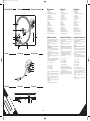
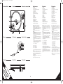
Bedienoberfläche
Seite 4
Controls
Panneau de commande
1
2
3
Bezeichnungen
Designation
Désignations
1.
2.
3.
4.
5.
6.
7.
8.
9.
10.
11.
12.
13.
14.
15.
16.
17.
18.
19.
20.
1.
2.
3.
4.
5.
6.
7.
8.
9.
10.
11.
12.
13.
14.
15.
16.
17.
18.
19.
20.
1.
2.
3.
4.
5.
6.
7.
8.
9.
10.
11.
12.
13.
14.
15.
16.
17.
18.
19.
20.
Plattenteller
Nabe
Spannungswahlschalter
EIN/AUS Schalter auf Plattentellerbeleuchtung
START /STOP Taster
33/45 Umschalter
Schalter für Nadelbeleuchtung
Pitchfader
Headshell mit Tonabnehmersystem
Tonarm
Tonarmstütze
Tonarmlift
Anti-Skating Rad
Gegengewichtsskala
Gegengewicht
Audio Ausgangskabel (Cinch)
GND Erdungskabel
Anschlussbuchse für Beatcounter
Anschlussbuchse für Fernbedienung
Anschlussbuchse für das Netzkabel
Table de lecture
Broche centrale
Sélecteur de tension
Interrupteur de l'éclairage de la table de lecture
Touche START/STOP
Commutateur 33/45
Touche pour l'éclairage de la cellule
Curseur Pitch
Cellule avec Pick Up
Bras de lecture
Support de bras de lecture
Lève-bras
Molette anti-dérapage
Graduation contre-poids
Contre-poids
Câble de sortie audio (coaxial)
Câble de terrage GND
Connecteur pour compteur de BPM
Connecteur pour télécommande
Connecteur pour le cordon secteur
8
4
5
6
Tonarm
7
Pick-up arm
Bras de lecture
Aufbau & Anschlüsse
Setting up & connections
Assemblage & connexions
1. Befestigen Sie den Plattenteller -1- auf dem Motor. Legen Sie
dazu den Plattenteller über die Plattentellernabe -2-.
2. Legen Sie das mitgelieferte Slipmat über die Nabe -2- auf den
Plattenteller.
3. Stecken Sie das Gegengewicht -15- auf den Tonarm.
HINWEIS!
Die Gegengewichtsskala -14- muss dabei auf der dem DJ
zugewandten Seite sein.
4. Schrauben sie das Headshell mit Tonabnehmersystem -9- in
den Tonarm -10- ein. Das Tonabnehmersystem lässt sich bei
Bedarf leicht austauschen:
a) Lösen Sie zunächst die Befestigungsschrauben an dem
Headshell und ziehen Sie die Kabel des mitgelieferten
Tonabnehmersystems ab.
b) Entfernen Sie das alte Tonabnehmersystem aus dem
Headshell.
c) Verbinden Sie nun die Anschlussdrähte des Headshells mit
den Anschlüssen des Tonabnehmersystems und beachten Sie
die Übereinstimmung der Drähtebelegung:
1. Attach the turntable -1- to the motor. For this place the
turntable above the hub -2-.
2. Place the supplied slipmat above the hub -2- onto the
turntable.
3. Place the balancing weight -15- onto the pick-up arm.
NOTE!
The balancing weight scale -14- must face toward the DJ.
4. Screw the headshell with the pick-up system -9- into the
pick-up arm -10-. The pick-up system is easy to exchange if
required:
a) First loosen the fastening screw on the headshell and
disconnect the cable of the supplied pick-up system.
b) Remove the old pick-up system from the headshell.
c) Now connect the leads of the pick-up system and observe
the assignment of wires:
1. Fixez la table de lecture -1- au moteur. Insérez la table de
lecture dans la broche centrale -2-.
2. Placez la feutrine sur la table de lecture en l'insérant dans la
broche centrale -2-.
3. Fixez le contre-poids -15- sur le bras de lecture.
REMARQUE !
La graduation de contre-poids -14- doit être dirigée vers
le DJ.
4. Vissez la cellule avec pick up -9- au bras de lecture -10-. La tête
de lecture se laisse aisément remplacer le cas échéant:
a) Dévissez d'abord les vis de fixation de la cellule et
débranchez le câble de la tête de lecture fournie avec
l'appareil.
b) Démontez la tête de lecture de la cellule.
c) Raccordez les câble de connexion de la cellule avec les
connecteurs du système et respectez l'affectation des câbles:
15
Farbe
Kanal und Polung
Weiß (L+)
Blau (L-)
Rot (R+)
Grün (L-)
Links, Plus-Pol
Links, Minus-Pol
Rechts, Plus-Pol
Rechts, Minus-Pol
14
13
12
11
5.
10
6.
9
7.
8.
Rückseite
Turntable
Hub
Voltage selector
ON/OFF switch turntable illumination
START/STOP button
33/45 selector
Switch for stylus illumination
Pitch fader
Headshell with pick-up system
Pick-up arm
Pick-up rest
Pick-up lift
Anti-skating wheel
Balancing weight scale
Balancing weight
Audio output cables (cinch)
GND grounding cable
Connecting socket for beat counter
Connecting socket for remote control
Connecting socket for mains line
Rear Panel
d) Ziehen Sie die Befestigungsschrauben an dem Headshell
fest an.
Verbinden Sie die Audio Ausgangskabel -16- mit den Audio
Eingängen Ihres Mixers und verbinden Sie das GND
Erdungskabel -17- mit der Erdungsschraube Ihres Mixers.
Verbinden Sie bei Bedarf einen Beatcounter mit der
Anschlussbuchse -18-.
Verbinden Sie bei Bedarf eine Fernbedienung mit der
Anschlussbuchse -19-.
Verbinden Sie das Netzkabel -20- mit einer Steckdose.
Colour
Channel and polarity
White (L+)
Blue (L-)
Red (R+)
Green (L-)
left, plus terminal
left, minus terminal
right, plus terminal
minus, minus terminal
Couleur
d) Tighten the fastening screws to the headshell.
5. Connect the audio output cable -16- with the audio input of
your mixer and connect the GND grounding cable -17- with the
grounding screw of your mixer.
6. If required connect a beat counter to connecting socket -18-.
7. If required connect a remote control to connecting socket -19-.
8. Connect the mains line with connecting socket -20- and an
outlet.
Canal et polarité
Blanc (L+) Gauche, positif
Bleu (L-) Gauche, négatif
Rouge (R+) Droite, positif
Vert (L-) Droite, négatif
d) Resserrez les vis de fixation de la cellule.
5. Branchez le câble de sortie audio -16- sur l'entrée audio de
votre console de mixage et raccordez le câble de terrage GND
-17- à la vis de terrage de votre console de mixage.
6. Connectez un compteur de BPM au connecteur -18- le cas
échéant.
7. Connectez une télécommande au connecteur -19- le cas
échéant.
8. Branchez le cordon secteur sur le connecteur d'alimentation
-20- et une prise secteur.
Face arrière
16
17
18
19
20
4
5