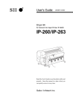
1
TL-WPA4230P AV500 Passthrough Powerline WiFi Extender REV1.0.0 1910011081 COPYRIGHT & TRADEMARKS Specifications are subject to change without notice. is a registered trademark of TP-LINK TECHNOLOGIES CO., LTD. Other brands and product names are trademarks or registered trademarks of their respective holders. No part of the specifications may be reproduced in any form or by any means or used to make any derivative such as translation, transformation, or adaptation without permission from TP-LINK TECHNOLOGIES CO., LTD. Copyright © 2014 TP-LINK TECHNOLOGIES CO., LTD. All rights reserved. http://www.tp-link.com FCC STATEMENT This equipment has been tested and found to comply with the limits for a Class B digital device, pursuant to part 15 of the FCC Rules. These limits are designed to provide reasonable protection against harmful interference in a residential installation. This equipment generates, uses and can radiate radio frequency energy and, if not installed and used in accordance with the instructions, may cause harmful interference to radio communications. However, there is no guarantee that interference will not occur in a particular installation. If this equipment does cause harmful interference to radio or television reception, which can be determined by turning the equipment off and on, the user is encouraged to try to correct the interference by one or more of the following measures: Reorient or relocate the receiving antenna. Increase the separation between the equipment and receiver. Connect the equipment into an outlet on a circuit different from that to which the receiver is connected. Consult the dealer or an experienced radio/ TV technician for help. This device complies with part 15 of the FCC Rules. Operation is subject to the following two conditions: 1) This device may not cause harmful interference. 2) This device must accept any interference received, including interference that may cause undesired operation. Any changes or modifications not expressly approved by the party responsible for compliance could void the user’s authority to operate the equipment. Note: The manufacturer is not responsible for any radio or tv interference caused by unauthorized modifications to this equipment. Such modifications could void the user’s authority to operate the equipment. FCC RF Radiation Exposure Statement: This equipment complies with FCC RF radiation exposure limits set forth for an uncontrolled environment. This device and its antenna must not be co-located or operating in conjunction with any other antenna or transmitter. “To comply with FCC RF exposure compliance requirements, this grant is applicable to only Mobile Configurations. The antennas used for this transmitter must be installed to provide a separation distance of at least 20 cm from all persons and must not be co-located or operating in conjunction with any other antenna or transmitter.” CE Mark Warning This is a class B product. In a domestic environment, this product may cause radio interference, in which case the user may be required to take adequate measures. Canadian Compliance Statement This device complies with Industry Canada license-exempt RSS standard(s). Operation is subject to the following two conditions: (1) This device may not cause interference, and (2)This device must accept any interference, including interference that may cause undesired operation of the device. Cet appareil est conforme aux norms CNR exemptes de licence d’Industrie Canada. Le fonctionnement est soumis aux deux conditions suivantes: (1) cet appareil ne doit pas provoquer d’interférences et (2) cet appareil doit accepter toute interférence, y compris celles susceptibles de provoquer un fonctionnement non souhaité de l’appareil. Industry Canada Statement Complies with the Canadian ICES-003 Class B specifications. Cet appareil numérique de la classe B est conforme à la norme NMB-003 du Canada. This device complies with RSS 210 of Industry Canada. This Class B device meets all the requirements of the Canadian interference-causing equipment regulations. Cet appareil numérique de la Classe B respecte toutes les exigences du Règlement sur le matériel brouilleur du Canada. Korea Warning Statements 당해 무선설비는 운용중 전파혼신 가능성이 있음. NCC Notice & BSMI Notice 注意! 依據 低功率電波輻射性電機管理辦法 第十二條 經型式認證合格之低功率射頻電機,非經許可,公司、商號或使用者均不得擅自變更頻率、加 大功率或變更原設計之特性或功能。 第十四條 低功率射頻電機之使用不得影響飛航安全及干擾合法通行;經發現有干擾現象時,應立即停用, 並改善至無干擾時方得繼續使用。前項合法通信,指依電信規定作業之無線電信。低功率射頻電機需忍受 合法通信或工業、科學以及醫療用電波輻射性電機設備之干擾。 減少電磁波影響,請妥適使用。 安全諮詢及注意事項 ●請使用原裝電源供應器或只能按照本產品注明的電源類型使用本產品。 ●清潔本產品之前請先拔掉電源線。請勿使用液體、噴霧清潔劑或濕布進行清潔。 ●注意防潮,請勿將水或其他液體潑灑到本產品上。 ●插槽與開口供通風使用,以確保本產品的操作可靠並防止過熱,請勿堵塞或覆蓋開口。 ●請勿將本產品置放於靠近熱源的地方。除非有正常的通風,否則不可放在密閉位置中。 ●請不要私自打開機殼,不要嘗試自行維修本產品,請由授權的專業人士進行此項工作。 Продукт сертифіковано згідно с правилами системи УкрСЕПРО на відповідність вимогам нормативних документів та вимогам, що передбачені чинними законодавчими актами України. Safety Information When product has power button, the power button is one of the way to shut off the product; when there is no power button, the only way to completely shut off power is to disconnect the product or the power adapter from the power source. Don’t disassemble the product, or make repairs yourself. You run the risk of electric shock and voiding the limited warranty. If you need service, please contact us. Avoid water and wet locations. This product can be used in the following countries: AT BG BY CA CZ DE DK EE ES FI FR GB GR HU IE IT LT LV MT NL NO PL PT RO RU SE SK TR UA US TP-LINK TECHNOLOGIES CO., LTD DECLARATION OF CONFORMITY For the following equipment: Product Description: AV500 Passthrough Powerline WiFi Extender Model No.: TL-WPA4230P Trademark: TP-LINK We declare under our own responsibility that the above products satisfy all the technical regulations applicable to the product within the scope of Council Directives: Directives 2004/108/EC, Directives 2006/95/EC, Directives 2011/65/EU Directives 1999/5/EC, Directives 1999/519/EC The above product is in conformity with the following standards or other normative documents: EN 55022: 2010 + AC: 2011 EN 55024: 2010 EN 61000-3-2: 2006 + A1: 2009 + A2: 2009 EN 61000-3-3: 2013 EN 60950-1: 2006 + A11: 2009 + A1: 2010 + A12: 2011 EN 50412-2-1: 2005 EN 62311: 2008 EN 300 328 V1.8.1 EN 301 489-1 V1.9.2 & EN 301 489-17 V2.2.1 The product carries the CE Mark: Person responsible for making this declaration: Yang Hongliang Product Manager of International Business Date of issue: 2014 TP-LINK TECHNOLOGIES CO., LTD. Building 24 (floors 1, 3, 4, 5), and 28 (floors 1-4) Central Science and Technology Park, Shennan Rd, Nanshan, Shenzhen, China Important Safety Instructions 1. Do not open this product or attempt to service it; it may expose you to dangerous high voltage or other risks. 2. Do not operate this product near water. 3. Do not place or operate this product near a radiator or a heat register. 4. Do not expose this product to dampness, dust or corrosive liquids. 5. Do not connect this product or disconnect it from a wall socket during a lightning or a thunderstorm. 6. Do not block the ventilation slots of this product, for insufficient airflow may harm it. 7. Do not put anything on this product. 8. Plug this product directly into a wall socket (100-240V~, 50/60Hz). Do not use an extension cord between this product and the AC power source. 9. When plugging this product into a wall socket, make sure that the electrical socket is not damaged, and that there is no gas leakage. 10. Place the connecting cables properly so that people won’t stumble or walk on it. 11. This product should be operated from the type of power indicated on the marking label. If you are not sure of the type of power available, consult the qualified technician. 12. Unplug this product from the mains and refer the product to qualified service personnel for the following conditions: If liquid has been spilled on the product If the product has been exposed to rain or water 13. Unplug this product from the wall socket before cleaning. Use a damp cloth for cleaning. Do not use liquid cleaners or aerosol cleaners. 14. The specification of the fuse is T4AL250V. To avoid damage, please do not change the fuse. 15. The Operating temperature is 0℃~40℃ (32℃~104℃). The Storage temperature is -40℃~70℃ (-40℃~158℃). CONTENTS Chapter 1 Introduction...................................................................................................... 1 1.1 System Requirement ................................................................................................ 1 1.2 Conventions ..................................................................................................................... 1 Chapter 2 Hardware Connection ............................................................................. 2 2.1 Before You Begin ......................................................................................................... 2 2.2 LED Indicator .................................................................................................................. 3 2.3 Physical Interface ........................................................................................................ 4 2.4 Hardware Connection ............................................................................................... 5 2.5 Wi-Fi Clone Button for Super Range Extension ................................... 7 Chapter 3 Configure the Device ............................................................................... 9 3.1 Login ...................................................................................................................................... 9 3.1.1 For Wired Connection ................................................................................................. 9 3.1.2 For Wireless Connection ....................................................................................... 11 3.2 Status .................................................................................................................................. 12 3.3 Network ............................................................................................................................. 13 3.4 Wireless ............................................................................................................................ 13 3.4.1 Wireless Settings ........................................................................................................... 14 3.4.2 Wireless Security ........................................................................................................... 15 3.4.3 Wireless MAC Filtering ............................................................................................ 18 3.4.4 Wireless Advanced ...................................................................................................... 20 3.4.5 Wireless Statistics ......................................................................................................... 21 3.5 Powerline ......................................................................................................................... 22 3.5.1 Network Settings ............................................................................................................ 22 3.5.2 Station Settings................................................................................................................ 22 3.6 System Tools ................................................................................................................. 24 3.6.1 Firmware Upgrade ....................................................................................................... 24 3.6.2 Factory Defaults.............................................................................................................. 26 3.6.3 Backup & Restore ......................................................................................................... 26 3.6.4 Reboot ...................................................................................................................................... 27 3.6.5 Password ............................................................................................................................... 27 3.6.6 System Log.......................................................................................................................... 28 Chapter 4 Connecting to Wireless Network ................................................ 29 4.1 In Windows 8................................................................................................................. 29 4.2 In Windows 7................................................................................................................. 30 4.3 In Windows Vista ........................................................................................................ 32 4.4 In Windows XP ............................................................................................................ 34 Chapter 5 Pair Button & Reset Button ............................................................. 36 5.1 Pair (Secure with 128 bits-AES) ..................................................................... 36 5.2 Setting Up a Powerline Network with the Pair Button .................... 36 5.3 Reset ................................................................................................................................... 37 Appendix A: Troubleshooting Guide ................................................................. 38 TL-WPA4230P Chapter 1 AV500 Passthrough Powerline WiFi Extender Introduction Congratulations on your purchase of this outstanding AV500 Passthrough Powerline WiFi Extender. This device is not only a powerline Ethernet extender which transforms your house’s existing electrical wiring into a ubiquitous networking infrastructure, but also a Wi-Fi Access Point which creates a wireless network allowing for greater range and mobility. As a powerline Ethernet extender, it uses the existing power lines installed in a home as a path to transmit digital data, voice, audio and video between devices. Simply plug this AV500 Passthrough Powerline WiFi Extender into an ordinary AC power outlet, and then your Cable/xDSL broadband connection or existing Ethernet (LAN) network can be easily extended to any other electrical outlet in any room of a house with the absence of cabling. With powerline data rates of 500Mbps, full multimedia application can easily be supported throughout the whole house. As a Wi-Fi Access Point, it can transmit wireless data at the rate of up to 300Mbps. With multiple protection measures including SSID broadcast control, wireless LAN WEP encryption, and Wi-Fi Protected Access (WPA2- PSK, WPA-PSK), the device delivers complete data privacy. It supports an easy, web-based management utility. Even though you may not be familiar with the device, you can easily configure it with the help of this Guide. The extender adds three new functions which are found to be useful. 1. Connection with a new unassociated device via the Pair button. 2. Reset to default settings via the Reset button. 3. Wi-Fi Clone via Wi-Fi Clone button. 1.1 System Requirement a) At least two power outlets (100-240V~, 50/60Hz) with standard home power wiring b) A computer with the following: Operating System of Windows 2000/XP/2003/Vista/7/8, Mac OS X, Linux Operating System with TCP/IP installed Pentium III compatible processor and above Ethernet LAN card installed with TCP/IP protocol 64 MB RAM or more 50 MB of free disk space (Minimum) CD-ROM Drive 1.2 Conventions The extender, or TL-WPA4230P, or device mentioned in this User Guide stands for TL-WPA4230P AV500 Passthrough Powerline WiFi Extender without any explanations. Parameters provided in the pictures are just references for setting up the product. They may differ from the actual situation. You can set the parameters according to your demand. 1 TL-WPA4230P Chapter 2 AV500 Passthrough Powerline WiFi Extender Hardware Connection 2.1 Before You Begin Please read this User Guide carefully before installing and using the equipment. The operating distance or range of your wireless connection varies significantly based on the physical placement of the powerline extender. Factors that can weaken signals by getting in the way of your network’s radio waves are metal appliances or obstructions, and walls. Typical ranges vary based on the types of materials and background RF (radio frequency) noise in your home or office. For best performance of your wireless network, you are suggested to place your powerline extender: 1). 2). 3). 4). Near the center of the area in which your wireless stations will operate. In an elevated location such as a high shelf. Away from the potential sources of interference, such as PCs, microwaves, and cordless phones. Away from large metal surfaces. Failure to follow these guidelines can result in significant performance degradation or inability to wirelessly connect to the powerline extender. Note: Take notes that this AV500 Passthrough Powerline WiFi Extender works in pairs or with another powerline device. You need to plug the powerline extender into a power outlet; you will also need another powerline extender or powerline Ethernet adapter connected to your Cable/xDSL broadband (Ethernet port) in order to extend your broadband connection or Internet surfing. With clean powerline, the distance between two powerline Ethernet extenders can reach 300 meters, but the actual distance may vary due to the environment. Section below describes the AV500 Passthrough Powerline WiFi Extender’s LED indicators, physical interface and hardware connection mechanism. 2 TL-WPA4230P AV500 Passthrough Powerline WiFi Extender 2.2 LED Indicator The LED indicator displays information about the device’s status. LEDs Name Power LED Status On The device is on. Off The device is off. Blinking Powerline LED Ethernet LED Wi-Fi/Wi-Fi Clone LED Indication The device is in the pairing procedure. On The device is connected to a powerline network, but there is no data being transferred. Off The device isn’t connected to any powerline network. Blinking The device is transferring data. On The Ethernet port is connected. Off The Ethernet port isn’t connected. Off The wireless function has been disabled. Blinking slowly The extender is cloning Wi-Fi settings from other device. Blinking quickly The wireless function has been enabled. 3 TL-WPA4230P AV500 Passthrough Powerline WiFi Extender 2.3 Physical Interface Here displays the physical items on this device. Integrated Electrical Socket Wi-Fi/Wi-Fi Clone Button Power Plug Ethernet Ports Reset Button Pair Button Item Description Wi-Fi/Wi-Fi Clone Button Press the button for 2 seconds to start Wi-Fi Clone. Press the button for 5 seconds to enable or disable the wireless function. Power Plug* A power plug for connecting the adapter to an AC power socket (100–240V~, 50/60Hz). Ethernet Port Three 10/100Mbps Ethernet ports connected to PC LAN card or broadband device. Reset Button Press the button more than 5 seconds, the device will restore to its factory defaults. Pair Button Pair button is used to secure a powerline network. The integrated electrical socket allows additional devices or multiple sockets to be Integrated connected to the adapter just like to a normal wall socket. No electrical socket is Electrical Socket lost. * The provided power plug may differ from the picture due to different regional power specifications. Here we take the EU version as an example. Note: 1. If you press the Pair button for more than 10 seconds, the extender will leave the network it is associated with and its network name assumes a random value. 2. For detailed information about the Reset button and Pair button, please refer to Chapter 5 Pair Button & Reset Button. 4 TL-WPA4230P AV500 Passthrough Powerline WiFi Extender 2.4 Hardware Connection Please first make sure that your PC can successfully access the Internet via the router. Then connect the powerline devices by following the instructions below. Step 1: Connecting to the Internet This section describes how to connect the powerline extender into your existing network. Follow the procedures described below: 1. Connect one end of an Ethernet (RJ45) cable to the Ethernet port of the powerline extender or a compatible powerline adapter like TL-PA4020P. 2. Connect the other end of the Ethernet (RJ45) cable to an available Ethernet port of your wireless router. 3. Plug the powerline extender or powerline adapter into a wall socket. 4. Check and confirm the LEDs status. (The Power LED and Ethernet LED on the powerline device should be ON.) The hardware connection mechanism is shown below: Note: Do not connect the powerline extender or powerline adapter to an extension lead, power strip, extension cord, or surge protector, as these may degrade the network performance. Step 2: Connecting the Computer Following are the steps to properly connect the powerline extender to your computer: 1. Connect one end of the provided Ethernet (RJ45) cable to the powerline extender’s Ethernet port. 2. Connect the other end of the Ethernet (RJ45) cable to you computer’s LAN port. 3. Plug the powerline extender into a wall socket next to the computer. 4. Turn on your computer. 5. Check and confirm that the Power LED and Ethernet LED on the powerline extender are ON. 5 TL-WPA4230P AV500 Passthrough Powerline WiFi Extender The hardware connection mechanism is shown below: As soon as the powerline devices are connected following the steps above, a powerline network is available. 6 TL-WPA4230P AV500 Passthrough Powerline WiFi Extender 2.5 Wi-Fi Clone Button for Super Range Extension Wi-Fi Clone button is used for copying the wireless settings (including SSID and wireless password) from the front wireless router. Wi-Fi Clone Steps: Before taking the steps below, we strongly recommend you make sure the current wireless password of the front router isn’t the default value. 1. Press the WPS button on the router for 2 seconds. (Here we take TP-LINK router as an example.) 2. Press the Wi-Fi Clone button on the extender for 2 seconds. The extender will reboot later. * It’s recommended that you plug the extender near the router to use Wi-Fi Clone button. After Wi-Fi Clone: A unified wireless network is established. The SSID and wireless password of the powerline extender will be the same as the wireless router. 7 TL-WPA4230P AV500 Passthrough Powerline WiFi Extender Note: If you want to establish a secure and separate wireless network from the wireless router, please refer to 3.4.2 Wireless Security to set a different SSID and password for your powerline extender. 8 TL-WPA4230P Chapter 3 AV500 Passthrough Powerline WiFi Extender Configure the Device This chapter describes how to configure your extender via the web-based management page. The AV500 Passthrough Powerline WiFi Extender is easy to configure and manage with the web-based (Internet Explorer, Netscape® Navigator, Firefox, Safari, Opera or Chrome) management page, which can be launched on any windows, Macintosh or UNIX OS with a web browser. 3.1 Login 3.1.1 For Wired Connection If your computer is connected to the extender via Ethernet cable, you can log in to the extender by following the steps below: 1. Insert the TP-LINK Resource CD into the CD-ROM drive. The following screen will appear. Select model TL-WPA4230P and then choose Management Utility from the drop-down menu. Figure 3-1 Setup Wizard Note: If your PC does not have a CD-ROM drive, please download the Management Utility at TP-LINK official website, www.tp-link.com. 9 TL-WPA4230P AV500 Passthrough Powerline WiFi Extender 2. Find the model to be configured and click Connect to log in to the web-based management utility. Figure 3-2 Management Utility Note: If another TL-WPA4230P is displayed on the screen above and you cannot decide which model is the one you are configuring, please refer to the MAC address under MAC Address column. The device’s MAC address can be found on the label at the bottom of the device. 3. Enter admin for the User name and Password (both in lower case letters) in the screen below. Then click OK or press Enter. Figure 3-3 Login Window 10 TL-WPA4230P AV500 Passthrough Powerline WiFi Extender Note: If the above screen does not prompt, it means that your web browser has been set to a proxy. Go to Tools >Internet Options>Connections>LAN Settings, in the screen that appears, cancel the Using Proxy checkbox, and click OK to finish it. 3.1.2 For Wireless Connection If your device is connected to the extender via wireless, you can log in to the extender by following the steps below: 1. Launch a web browser and type in the default domain name http://tplinkplclogin.net in the address field. Figure 3-4 Log in to the Extender 2. Enter admin for the User name and Password (both in lower case letters) in the screen below. Then click OK or press Enter. Figure 3-5 Login Windows Note: If the above screen does not prompt, it means that your web browser has been set to a proxy. Go to Tools>Internet Options>Connections>LAN Settings, in the screen that appears, cancel the Using Proxy checkbox, and click OK to finish it. After a successful login, you can configure and manage the device. There are six main menus on the leftmost column of the web-based management page: Status, Network, Wireless, Powerline and System Tools. Submenus will be available after clicking one of the main menus. On the right of the web-based management page lays the detailed explanations and instructions for the corresponding page. 11 TL-WPA4230P AV500 Passthrough Powerline WiFi Extender 3.2 Status The Status page displays the powerline extender’s current status and configuration. All information is read-only. Figure 3-6 Status Firmware Version - This field displays the current firmware version of the powerline extender. Hardware Version - This field displays the current hardware version of the powerline extender. Powerline - This field displays the current settings or information for powerline, including the MAC address, Device Password and Network Name which can be configured on the Powerline → Network Settings page. MAC Address - The physical address of the powerline extender, as seen from powerline. Device Password - The security ID that restricts access to critical device functions. Network Name - The name that identifies a logical network. Network - The following parameters apply to the Ethernet port of the powerline extender. You can configure them on the Network page. MAC Address - The physical address of the powerline extender's Ethernet port. IP Address - The IP address of the powerline extender. Subnet Mask - The subnet mask associated with IP address. 12 TL-WPA4230P AV500 Passthrough Powerline WiFi Extender Wireless - This field displays the current settings or information for wireless. They can be configured on the Wireless → Wireless Settings page. Wireless Radio - Indicates whether the wireless radio feature of the powerline extender is enabled or disabled. Name (SSID) - The SSID of the powerline extender. Channel - The wireless channel in use. Mode - The current wireless mode the powerline extender works on. Channel Width - The bandwidth of the wireless channel. MAC Address - The physical address of the powerline extender, as seen from the WLAN. System Up Time - This filed displays the length of the time since the powerline extender was last powered on or reset. Click the Refresh button to get the latest status and settings of the powerline extender. 3.3 Network You can configure the IP parameters of the powerline extender on this page. Figure 3-7 Network MAC Address - The physical address of the powerline extender's Ethernet port. The value can not be changed. IP Address - Enter the IP address of the powerline extender in dotted-decimal notation (factory default setting is 192.168.1.1). Subnet Mask - An address code that determines the size of the network. Usually it is 255.255.255.0. Click the Save button to save your settings. Note: 1. If you change the IP address, you must use the new IP address to log in to the powerline extender. 2. If the IP address of the powerline extender conflicts with other device in the intranet, a temporary IP address will be generated at random. 3.4 Wireless The Wireless option, improving functionality and performance for wireless network, can help you make the powerline extender an ideal solution for your wireless network. Here you can create a wireless local 13 TL-WPA4230P AV500 Passthrough Powerline WiFi Extender area network just through a few settings. Wireless Settings is used for the configuration of some basic parameters of the powerline extender. Wireless Security provides three different security types to secure your data and thus providing greater security for your wireless network. MAC filtering allows you to control the access of wireless stations to the powerline extender. Wireless Advanced allows you to configure some advanced parameters for the powerline extender. Wireless statistics enables you to get detailed information about the current connected wireless stations. There are five submenus under the Wireless menu (shown in Figure 3-8): Wireless Settings, Wireless Security, Wireless MAC Filtering, Wireless Advanced and Wireless Statistics. Click any of them and you will be able to configure the corresponding function. The detailed explanations for each submenu are provided below. Figure 3-8 Wireless menu 3.4.1 Wireless Settings Selecting Wireless > Wireless Settings will enable you to configure the basic settings for your wireless network on the screen below (Figure 3-9). Figure 3-9 Wireless Settings SSID (Set Service Identifier) - Identifies your wireless network name. Enter a value of up to 32 characters. The same Name (SSID) must be assigned to all wireless devices in your network. The default SSID is TP-LINK_XXXXXX (XXXXXX indicates the last six unique characters of each device’s MAC address). This value is case-sensitive. For example, TEST is not the same as test. Region - Select your region from the pull-down list. This field specifies the region where the wireless function of the powerline extender can be used. It may be illegal to use the wireless function of the powerline extender in a region other than one of those specified in this filed. If your country or region is not listed, please contact your local government agency for assistance. 14 TL-WPA4230P AV500 Passthrough Powerline WiFi Extender When you select your local region from the pull-down list, click the Save button, then the Note Dialog appears. Click OK. Note Dialog Channel - This field determines which operating frequency will be used. It is not necessary to change the wireless channel unless you notice interference problems with another nearby access point. If you select Auto, then the powerline extender will choose the best channel automatically. Mode - Select the desired wireless mode. The options are: 11b only - Only 802.11b wireless stations can connect to the device. 11g only - Only 802.11g wireless stations can connect to the device. 11n only - Only 802.11n wireless stations can connect to the device. 11bg mixed - Both 802.11b and 802.11g wireless stations can connect to the device. 11bgn mixed - All 802.11b, 802.11g and 802.11n wireless stations can connect to the device. If all of the wireless devices connected with the powerline extender can connect in the same transmission mode (e.g. 802.11b), you can choose the Only mode (e.g. 11b only). If you have some devices that use different transmission modes, choose the appropriate Mixed mode. Channel Width - Determines the channel width to be used. It is unnecessary to change the default value unless required. Enable Wireless Powerline Extender Radio - The wireless radio of the powerline extender can be enabled or disabled to allow or deny wireless stations to access. If it is enabled, the wireless stations will be able to access the powerline extender; otherwise, wireless stations will not be able to access the powerline extender. Enable SSID Broadcast - Selecting this check box will allow the device to broadcast its name (SSID) on the air. If it’s allowed, when wireless clients survey the local area for wireless networks to associate with, they will detect the SSID broadcast by the device. Note: To apply any settings you have altered on the page, please click the Save button to make the settings take effect. 3.4.2 Wireless Security Selecting Wireless > Wireless Security will enable you to configure wireless security for your wireless network to protect your data from intruders. The powerline extender provides three security types: WEP, WPA/WPA2 and WPA-PSK/WPA2-PSK. The default password can be found on the label at the bottom of the device. Wireless security can be configured on the following screen shown as Figure 3-10. 15 TL-WPA4230P AV500 Passthrough Powerline WiFi Extender Figure 3-10 Wireless Security Disable Security - Check this radio button to disable wireless security. If disabled, the wireless stations will be able to connect this device without encryption. It is strongly recommended that you choose one of the security types to enable security. WPA-PSK/ WPA2-PSK - Select WPA based on pre-shared key. Figure 3-11 WPA-PSK/WPA2-PSK Version - You can select one of following versions. Automatic - Select WPA-PSK or WPA2-PSK automatically based on the wireless station's capability and request. WPA-PSK - Pre-shared key of WPA. WPA2-PSK - Pre-shared key of WPA2. Encryption - When you select WPA-PSK or WPA2-PSK for Authentication Type, you can select either Automatic, TKIP or AES as Encryption. PSK Password - Enter a password here. Group Key Update Period - Specify the group key update interval in seconds. The value can be either 0 or at least 30. Enter 0 to disable the update. 16 TL-WPA4230P AV500 Passthrough Powerline WiFi Extender WPA/WPA2 - Select WPA/WPA2 based on Radius Server. Figure 3-12 WPA/WPA2 Version - You can select one of following versions. Automatic - Select WPA or WPA2 automatically based on the wireless station's capability and request. WPA - Wi-Fi Protected Access. WPA2 - WPA version 2. Encryption - You can select either Automatic, TKIP or AES. Radius Server IP - Enter the IP address of the Radius Server. Radius Port - Enter the port used by radius service. Radius Password - Enter the password for the Radius Server. Group Key Update Period - Specify the group key update interval in seconds. The value can be either 0 or at least 30. Enter 0 to disable the update. WEP - Select 802.11 WEP security. Figure 3-13 WEP Type - You can select one of following types. Automatic - Select Shared Key or Open System authentication type automatically based on the wireless station's capability and request. Shared Key - Select 802.11 Shared Key authentication type. Open System - Select 802.11 Open System authentication type. WEP Key Format - You can select ASCII or Hexadecimal format. ASCII format stands for any combination of keyboard characters in the specified length. Hexadecimal format stands for any combination of hexadecimal digits (0-9, a-f, A-F) in the specified length. WEP Key - Select which of the four keys will be used and enter the matching WEP key information for your network in the selected key radio button. These values must be identical on all wireless stations in your network. 17 TL-WPA4230P AV500 Passthrough Powerline WiFi Extender Key Type - You can select the WEP key length (64-bit, or 128-bit) for encryption. "Disabled" means this WEP key entry is invalid. For 64-bit encryption - You can enter 10 hexadecimal digits (any combination of 0-9, a-f, A-F, zero key is not permitted) or 5 ASCII characters. For 128-bit encryption - You can enter 26 hexadecimal digits (any combination of 0-9, a-f, A-F, zero key is not permitted) or 13 ASCII characters. Note: If you do not set the key, the wireless security function is still disabled even if you have selected Shared Key as Authentication Type. Be sure to click the Save button to save your settings on this page. 3.4.3 Wireless MAC Filtering Selecting Wireless > Wireless MAC Filtering will allow you to set up some filtering rules to control wireless stations accessing the device, which depends on the station’s MAC address on the following screen as shown in Figure 3-14. Figure 3-14 Wireless MAC Filtering Wireless MAC Filtering - Click the Enable button to enable the Wireless MAC Address Filtering. The default setting is disabled. To Add a Wireless MAC Address filtering entry, click the Add New… button. The “Add or Modify Wireless MAC Address Filtering entry" page will appear, shown in Figure 3-15. Figure 3-15 Add or Modify Wireless MAC Address Filtering entry 18 TL-WPA4230P AV500 Passthrough Powerline WiFi Extender MAC Address - Enter the wireless station's MAC address that you want to control. Description - Give a simple description of the wireless station. Status - Select a status for this entry, either Enabled or Disabled. To set up an entry, follow these instructions: First, you must decide whether the unspecified wireless stations can access the device or not. If you desire that the unspecified wireless stations can access the device, please select the radio button Allow the stations not specified by any enabled entries in the list to access, otherwise, select the radio button Deny the stations not specified by any enabled entries in the list to access. To add a MAC Address Filtering entry, follow these instructions: 1. Enter the appropriate MAC Address into the MAC Address field. The format of the MAC Address is XX-XX-XX-XX-XX-XX (X is any hexadecimal digit). For example: 00-0A-EB-B0-00-0B. 2. Enter a simple description of the wireless station in the Description field. For example: wireless station A. 3. Select Enabled or Disabled for this entry on the Status pull-down list. 4. Click the Save button to save this entry. To add additional entries, repeat steps 1-4. To modify or delete an existing entry: 1. Click the Modify in the entry you want to modify. If you want to delete the entry, click the Delete. 2. Modify the information. 3. Click the Save button. Click the Enable All button to make all entries enabled Click the Disabled All button to make all entries disabled. Click the Delete All button to delete all entries Click the Next button to go to the next page and click the Previous button to return to the previous page. For example: If you desire that the wireless station A with MAC address 00-0A-EB-00- 07-BE is able to access the device, while all other wireless stations cannot access the device, you should configure the Wireless MAC Address Filtering list by following these steps: 1. Click the Enable button to enable this function. 2. Select the radio button: Deny the stations not specified by any enabled entries in the list to access for Filtering Rules. 3. Delete all or disable all entries if there are any entries already. 19 TL-WPA4230P AV500 Passthrough Powerline WiFi Extender 4. Click the Add New... button and enter the MAC address 00-0A-EB-00-07-BE in the MAC Address field, enter Wireless Station A in the Description field and select Enabled in the Status pull-down list. Click the Save button. The filtering rules that configured should be similar to the following list: Note: If you enable the function and select Deny the stations not specified by any enabled entries in the list to access for Filtering Rules but there isn’t any enabled entry in the list, thus, no wireless stations can access the device. 3.4.4 Wireless Advanced Selecting Wireless > Wireless Advanced will allow you to do some advanced settings for the device in the following screen shown in Figure 3-16. As the configuration for each operation mode is almost the same, we take Access Point mode for example here. Figure 3-16 Wireless Advanced Transmit Power - Specifies the transmit power of the device. You can select High, Middle or Low based on your need. High is the default setting and is recommended. Beacon Interval - Specifies a value between 40-1000 milliseconds. The beacons are the packets sent by the device to synchronize a wireless network. Beacon Interval value determines the time interval of the beacons. The default value is 100. RTS Threshold - Specifies the RTS (Request to Send) Threshold. If the packet is larger than the specified RTS Threshold size, the device will send RTS frames to a particular receiving station and negotiate the sending of a data frame. The default value is 2346. Fragmentation Threshold - This value is the maximum size determining whether packets will be fragmented. Setting the Fragmentation Threshold too low may result in poor network performance since excessive packets. 2346 is the default setting and is recommended. 20 TL-WPA4230P AV500 Passthrough Powerline WiFi Extender DTIM Interval - Determines the interval of the Delivery Traffic Indication Message (DTIM). You can specify the value between 1-255 Beacon Intervals. The default value is 1, which indicates the DTIM Interval is the same as Beacon Interval. Enable WMM - WMM function can guarantee the packets with high- priority messages being transmitted preferentially. It is strongly recommended that this function be enabled. Enable Short GI - This function is recommended for it will increase the data capacity by reducing the guard interval time. Enable AP Isolation - Isolates all connected wireless stations so that wireless stations cannot access each other through WLAN. Note: If you are not familiar with the setting items on this page, it's strongly recommended that you keep the provided default values; otherwise, it may result in low wireless network performance. 3.4.5 Wireless Statistics Selecting Wireless > Wireless Statistics will allow you to see the wireless transmission information in the following screen shown in Figure 3-17. This page shows MAC Address, Current Status, Received Packets and Sent Packets for each connected wireless station. Figure 3-17 Statistics of the device attached wireless stations MAC Address - Shows the connected wireless station's MAC address. Current Status - The connected wireless station's running status, one of STA-AUTH / STA-ASSOC / STA-JOINED / WPA / WPA-PSK / WPA2 / WPA2-PSK / AP-UP / AP-DOWN / Disconnected. Received Packets - Packets received by the station. Sent Packets - Packets sent by the station. You cannot change any of the values on this page. To update this page and to show the current connected wireless stations, click the Refresh button. If the numbers of connected wireless stations go beyond one page, click the Next button to go to the next page and click the Previous button to return to the previous page. Note: This page will be refreshed automatically every 5 seconds. 21 TL-WPA4230P AV500 Passthrough Powerline WiFi Extender 3.5 Powerline There are two submenus under the Powerline menu: Network Settings and Station Settings. Click any of them, and you will be able to configure the corresponding function. The detailed explanations for each submenu are provided below. Figure 3-18 Powerline menu 3.5.1 Network Settings Selecting Powerline > Network Settings, and you can configure the network name of the powerline extender or all the stations in current network on this page. Figure 3-19 Network Settings MAC Address - The physical address of the powerline extender, as seen from the powerline. The value can not be changed. Device Password - The password of the powerline extender. The value can not be changed. Network Name - Enter the network name (factory default - HomePlugAV). Click the Default button to enter the default network name. Click the Set Local button to set the powerline extender. Click the Set All button to set all stations which entered the correct passwords in current network, including the powerline extender. Note: If you set all stations network name, the remote ones which power off or entered the wrong password will not take effect. 3.5.2 Station Settings The Station Settings page shows remote stations in current network and allows you to enter, modify or delete the password and name for each station. 22 TL-WPA4230P AV500 Passthrough Powerline WiFi Extender Figure 3-20 Station Settings MAC Address - The remote station's MAC address. The value can not be changed. Device Password - The security ID of remote station. Device Name - The name used for identifying a station. To add or modify a station entry, click the Add or Modify button in operation column and following these instructions: 1. 2. 3. Enter the station password in Device Password field. The format of the password is XXXX-XXXX-XXXX-XXXX (X is any character). For example, RLXL-BYPI-MZBO-OPAB. Enter a name you want to give the station in the Device Name field or leave it empty. For example, Station A. Click the Save button to save this entry. Figure 3-21 Add or Modify PLC Station entry To add or modify another entries, repeat steps 1~3. Click the Delete button in the operation column to delete a station entry. Click the Add New... button to add a station into current network. The steps are the same as adding a station entry. 23 TL-WPA4230P AV500 Passthrough Powerline WiFi Extender Figure 3-22 Add a new station Click the Refresh button to update the current connected stations. Click the Next button to go to the next page and click the Previous button to return to the previous page. Note: You can do Add or Modify operation only when the remote station is connected. If the remote station which you entered the password is power off or leave the current network, you can only do Delete operation. 3.6 System Tools System Tools option helps you to optimize the configuration of your device. You can upgrade the powerline extender to the latest version of firmware as well as backup or restore the device’s configuration files. It’s suggested that you change the default password to a more secure one because it controls access to the device’s web-based management page. Besides, you can find out what happened to the system in System Log. There are six submenus under the System Tools menu (shown as Figure 3-23): Firmware Upgrade, Factory Defaults, Backup & Restore, Reboot, Password and System Log. Clicking any of them will enable you to configure the corresponding function. The detailed explanations for each submenu are provided below. Figure 3-23 The System Tools menu 3.6.1 Firmware Upgrade Selecting System Tools > Firmware Upgrade allows you to upgrade the latest version of firmware for the device on the screen shown in Figure 3-24. 24 TL-WPA4230P AV500 Passthrough Powerline WiFi Extender Figure 3-24 Firmware Upgrade New firmware versions are posted at http://www.tp-link.com and can be downloaded for free. Firmware Version - Here displays the current firmware version. Hardware Version - Here displays the current hardware version. The hardware version of the upgrade file must accord with the current hardware version. Note: 1 There is no need to upgrade the firmware unless the new firmware has a new feature you want to use. However, when experiencing problems caused by the device itself, you can try to upgrade the firmware. 2 Before upgrading the device’s firmware, you should write down some of your customized settings to avoid losing important configuration settings of device. To upgrade the device's firmware, follow these instructions: 1. Download a more recent firmware upgrade file from the TP-LINK website (http://www.tp-link.com). 2. Enter the path name or click Browse… to select the downloaded file on the computer into the File blank. 3. Click Upgrade. 4. The powerline extender will reboot while the upgrade has been finished. Note: The firmware version must correspond to the hardware. The upgrade process takes a few moments and the powerline extender restarts automatically when the upgrade is complete. It is important to keep power applied until the system finishes upgrading and rebooting. Loss of power during the upgrade could damage the powerline extender. 25 TL-WPA4230P AV500 Passthrough Powerline WiFi Extender 3.6.2 Factory Defaults Selecting System Tools > Factory Defaults allows you to restore the factory default settings for the device on the screen shown in Figure 3-25. Figure 3-25 Restore Factory Defaults Click Restore to reset all configuration settings to their default values. Default User Name: admin Default Password: admin Default IP Address: 192.168.1.1 Default Subnet Mask: 255.255.255.0 Note: Any settings you have saved will be lost when the default settings are restored. 3.6.3 Backup & Restore Selecting System Tools > Backup & Restore allows you to save all configuration settings to your local computer as a file or restore the device's configuration on the screen shown in Figure 3-26. Figure 3-26 Save or Restore the Configuration Click Backup to save all configuration settings to your local computer as a file. To restore the device's configuration, follow these instructions: Click Browse… to find the configuration file which you want to restore. Click Restore to update the configuration with the file whose path is the one you have input or selected in the blank. Note: 1. The current configuration will be covered with the uploading configuration file. 2. Wrong process will lead the device unmanaged. 3. The restoring process lasts for about 20 seconds and restarts automatically. Do not power off the device during the process to avoid any damage. 26 TL-WPA4230P AV500 Passthrough Powerline WiFi Extender 3.6.4 Reboot Selecting System Tools > Reboot allows you to reboot the device on the screen shown in Figure 3-27. Figure 3-27 Reboot the device Click the Reboot button to reboot the device. Some settings of the device will take effect only after rebooting, which include: Change the powerline extender's IP Address (system will reboot automatically). Upgrade the firmware of the powerline extender (system will reboot automatically). Restore the powerline extender's settings to the factory defaults (system will reboot automatically). Update the configuration with the file (system will reboot automatically). 3.6.5 Password Selecting System Tools > Password allows you to change the factory default user name and password of the device on the screen shown in Figure 3-28. Figure 3-28 Password It is strongly recommended that you change the factory default user name and password of the device. All users who try to access the device's web-based management page or Quick Setup will be prompted for the device's user name and password. Note: The new user name and password must not exceed 14 characters in length and must not include any spaces. Enter the new Password again to confirm it. Click Save when finished. Click Clear All to clear all. 27 TL-WPA4230P AV500 Passthrough Powerline WiFi Extender 3.6.6 System Log Selecting System Tools > System Log allows you to query the Logs of the device on the screen shown in Figure 3-29. Figure 3-29 System Log The device can keep logs of all traffic. You can query the logs to find what happened to the device. Click the Refresh button to show the latest log list. Click the Clear All button to clear all logs. 28 TL-WPA4230P Chapter 4 AV500 Passthrough Powerline WiFi Extender Connecting to Wireless Network The default SSID is TP-LINK_××××××. (×××××× stand for the last six unique numbers of the WLAN MAC which can be found on the label at the bottom of the device.) The default Wireless Password can also be found on the label of the device. If you have used the Wi-Fi Clone button to clone Wi-Fi settings from the front router, the SSID and wireless password of the powerline extender will be the same as the wireless router. If you have established a secure and separate wireless network from the wireless router, the SSID and wireless password of the powerline extender will be what you have set. 4.1 In Windows 8 If you are using Windows 8, please follow the steps below to connect to the wireless network of the powerline extender. 1. Click the icon Connect. 2. Input the network security key and then click Next. at the bottom of your desktop, select the SSID of TL-WPA4230P and then click Note: If your network is an unsecured network, you will not be prompted to input the network key. 3. Click to select whether to turn on sharing and connect to devices. 29 TL-WPA4230P 4. AV500 Passthrough Powerline WiFi Extender You have joined the home network and can surf the Internet now. 4.2 In Windows 7 Windows 7 users may use the built-in wireless utility. Follow the steps below. 1. Click the icon at the bottom of your desktop, select the SSID of TL-WPA4230P and then click Connect. 30 TL-WPA4230P AV500 Passthrough Powerline WiFi Extender Figure 4-1 2. Input the network key and then click OK. Figure 4-2 Note: If your network is an unsecured network, you will not be prompted to input the network key. 3. You have joined the home network and can surf the Internet now. 31 TL-WPA4230P AV500 Passthrough Powerline WiFi Extender Figure 4-3 4.3 In Windows Vista Windows Vista users may use the built-in wireless utility. Follow the steps below. 1. Right-click the icon at the bottom of your screen, then click Connect to a network. Figure 4-4 2. Select the SSID of TL-WPA4230P and then click Connect. 32 TL-WPA4230P AV500 Passthrough Powerline WiFi Extender Figure 4-5 3. Input the network key and then click OK. Figure 4-6 Note: If your network is an unsecured network, you will not be prompted to input the network key. 4. You have joined the home network and can surf the Internet now. Click Close to finish the connection. 33 TL-WPA4230P AV500 Passthrough Powerline WiFi Extender Figure 4-7 4.4 In Windows XP Windows XP users may use the built-in wireless utility. Follow the steps below. 1. Click the icon Connect. at the bottom of your desktop, select the SSID of TL-WPA4230P and then click Figure 4-8 2. Input the network key and then click Connect. 34 TL-WPA4230P AV500 Passthrough Powerline WiFi Extender Figure 4-9 Note: If your network is an unsecured network, you will not be prompted to input the network key. 35 TL-WPA4230P Chapter 5 AV500 Passthrough Powerline WiFi Extender Pair Button & Reset Button 5.1 Pair (Secure with 128 bits-AES) The Homeplug AV standard uses 128-bit AES (Advanced Encryption Standard) to safely transmit data between powerline dvices. For the powerline devices to communicate with each other, they all need to use the same Network Membership Key (NMK). Otherwise, they cannot unscramble the encrypted data sent in the powerline network. The Pair button allows you to set up a secure powerline connection with other HomePlug AV compliant powerline devices which also support the Pair feature. Here takes TP-LINK powerline devices for example (TL-WPA4230P for device A, TL-PA4020P for device B and C). 5.2 Setting Up a Powerline Network with the Pair Button You can connect a number of devices on a powerline network, but you can use the Pair button on only two devices at a time. Create a Powerline network using the Pair button: Step 1. Press and hold the Pair button of powerline device A TL-WPA4230P for one second, the Power LED will start flashing. Step 2. Within two minutes, press and hold the Pair button of powerline device B TL-PA4020P for one second, the Power LED will start flashing. Step 3. Wait for about 60 seconds while your powerline device A and B are connecting. The Power LED on both devices will stop flashing and become solid light when the connection is made. Join an existing Powerline network: Powerline device A and B have formed a powerline network, and powerline device C wants to join this network. Step 1. Press and hold the Pair button on powerline device C TL-PA4020P for one second. Step 2. Within two minutes, press and hold the Pair button on Powerline device A/B for one second. Step 3. Wait for about 60 seconds while your powerline devices are connecting. The Power LED on powerline device A/B and C will stop flashing and become solid light when the connection is made. Note: The sequence of Step 1 and Step 2 can be exchanged. Leave an existing Powerline network: Powerline device A, B and C have formed a powerline network, and the user wants to remove one device (powerline adapter C) from this network. Step 1. Press and hold the Pair button on powerline device C for at least 10 seconds. Powerline device C will reset and restart. Step 2. Wait for the reset to complete. 36 TL-WPA4230P AV500 Passthrough Powerline WiFi Extender 5.3 Reset To reset the powerline device: Press and hold the Reset button more than 5 seconds, and then release the button. You will see all LEDs begin to flash. At this moment, the default settings have been restored. Be careful, don’t power off when the device is in reset process. 37 TL-WPA4230P AV500 Passthrough Powerline WiFi Extender Appendix A: Troubleshooting Guide 1. The Power LED does not light up. Ans. Check the following: 1) Make sure that the powerline extender is properly plugged into a power outlet. 2) Make sure the power outlet is active (working) by plugging another electric device into it. 3) Re-plug the powerline extender to the power outlet. 4) If the Power LED still fails to light up, contact your local dealer for technical support. 2. The Ethernet LED does not light up. Ans. Check the following: 1) Make sure that the Ethernet cable (RJ45) is properly connected to the powerline extender’s Ethernet port and the other end of the Ethernet cable (RJ45) is properly connected to the computer LAN card or to your Cable/xDSL Ethernet port. 2) Make sure your computer LAN card is properly installed and configured. 3) Make sure your Cable/xDSL broadband access is working and configured correctly. 4) Contact your local dealer for technical support if the Ethernet LED still fails to light up after the above procedures. 3. The Powerline LED does not light up. Ans. Check the following: 1) Double-click to enable the Management Utility and click the “Rescan” button. The Management Utility will automatically detect all other Powerline Extender on your powerline network. 2) Try to plug a powerline device into a nearby power outlet and check whether the Powerline LED lights up or not. 3) Make sure that the device is plugged into a wall socket instead of a power strip. 4) Follow the method in “5.2 Setting Up a Powerline Network with the Pair Button” to establish the connection again. 5) Reset the device to its factory default values. 6) Contact your local dealer for technical support if the Powerline LED still fails to light up after the above procedures. 38