1
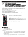
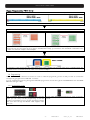
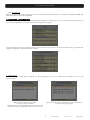
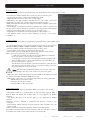
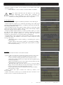
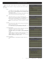
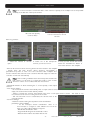
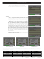
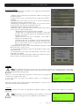
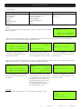
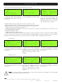
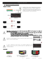
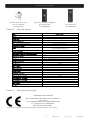
TWSF 310 CI
USER’S MANUAL
User’s manual · TWSF 310 CI
NOTE: This user’s guide is adapted to software version v.0.1.37 of TWSF 310 CI dated
04/04/2012.
For future software updates, you can download the user’s guide from the following website:
http://www.ftemaximal.com/
Chapter 1.
Installation.
1.1. Safety Measures
1.- Never place the device next to hot sources.
2.- Never undergo the device to temperatures that exceed its level of operation.
3.- Never expose the device to leakings nor spatterings.
4.- Never place objects that contain liquids over the device.
5.- Respect the ventilation slots of the device, do not cover them with any kind of object.
6.- The space around the device must be free of objects, in a minimum radius of 40cm.
7.- Avoid locations with possibilities of spilling liquids on the inside of the device, and with important changes of
temperature.
8.- Never open the device by yourself due to electric risk. In case of problems, go always to qualified technicians
9.- Never, under no circumstances, open the device when connected to the electrical net.
10.- During the handling it is better to disconnect the device from the electrical net.
11.- Obey the electricity security rules during the assembling. Use materials that obey the current law.
12.- The connecting plug must be accessible in a fast and simple way to have a fast disconnection.
13.- Never touch the plug with wet hands. Also, disconnect always the device before handling the connections.
14.- Never put any heavy object over the device, since it could get damaged.
15.- If the device is going to remain some time without use, it is recommendable to disconnect it from the electrical net.
16.- The repairmen and the maintenance of the device must be done by TV and radio specialised technicians.
1.2. Box content
Quick installation guide
2 x Link F male – F male
DC Cable
TWSF 310 CI
Cable 12 cm PIN to PIN RJ45 – RJ45
Stopper
-1-
TWSF 310 CI
version_en_1.0
FTE maximal
User’s manual · TWSF 310 CI
The TWSF 310 CI will be provided with a double DVB-T output that will allow distributing the channels
of the tuned transponders in two consecutive multiplex.
In order to configure the device we will have two selectable modules.
The options of configuration are independent. With the following exceptions:
- The output channel of the second module will be set automatically as the consecutive channel
after the one configured in the first module.
- The output level of the multiplex will be set by the output level configured in the first module.
1.3. Description and connections
The module TWSF 310 CI is used for the reception of free channels that obey the DVB-S/DVB-S2 standards. Each
module allows the reception of two complete transponders in DVB-S (QPSK) / DVB-S2 (QPSK/8PSK), and the
subsequent modulation in DVB-T (COFDM) of them.
A feature of this equipment is its modulator in Vestigial Side Band (or VSB). This modulation can be used to distribute
adjacent channels in one distribution without any intermodulation problem.
Each module has one Loop connector to cascade several modules at input and a Mix connector to do same in output
channels.The output channel is selectable between C2 and C69.
All parameters are programmed by the means of PRO 201 or the EVO or MINI series of field strength meter, and they are
monitored in the display of programmer or in the TFT screen of field strength meter.
TWSF 310 CI has two Common Interface slots.
TWSF 310 CI
1
5
6
7
2
8
9
10
1. Two-colored led*: It indicates the different states of the device.
2. CI: Common Interface.
3. OUT: This connector supplies the modulated channel according to the selected
standard in the module and mixes it with all the signals that it receives through the MIX
connector
4. MIX: Input of mixing of the module.
5. LNC IN: To connect to the LNC or to the LOOP OUT output of the previous module
6. LOOP OUT: To connect to the ANT IN input of the next module.
7. RS 232: Ethernet connector to cascade modules with the RCM 310 telecontrol unit
with the RJ45/RJ45 cable provided.
8. PRO 201: Ethernet connector to make the programming with the programmer.
9. LNC IN 2: Second input to connect to the LNC.
10. DC connectors: It has two connectors for input/output.
3
4
*States of two-colored leds
1. Initialization mode
- Green: main application charged.
- Blinking Green: Completing the initial sequence, at the moment when the module gets initialized, the led will turn
into one of the states the operating mode.
- Red: Phase of initializing the module.
2. Operative Mode
- Green: The system is working properly.
- Orange: At least one critical event has been recorded in the module. The led will only change into green when
the registration of events has been read by the programmer.
- Red: Error or alert detected in the running of the device, the led will be on only as long as the error/alert is
present. Once the error or the alert disappears, the led will change into orange because the error/alert is stored in
the registration of events.
3. Programming mode
- When the module detects an external programmer, the led will blink in the next sequence: green-orange-red.
- Once you leave the programming mode, the led will turn into the corresponding operating mode.
-2-
TWSF 310 CI
version_en_1.0
FTE maximal
User’s manual · TWSF 310 CI
Stages of transmodulator TWSF 310 CI
Input 1
Input 2
Selection of a tuned satellite transponder
Transmodulation
TP 1
TP 2
The tuned channels of the transponders are modulated according to the DVB-T rules in two multiplex. In cases where the
transponder has encoded channels, if you wish to distribute them freely, you will have to link a PCMCIA + subscriber card
to each one of the two outputs of the multiplex.
Out
Configuration of the channel and the output parameters of the multiplex. The channel of the second multiple will be set
by default as the consecutive channel of the one in the first multiplex.
1.4. Programming
TWSF 310 CI has two ethernet connectors. In order to make the programming of the module you have to connect the
corresponding programmer to PRO 201 connector.
You can make the programming through the PRO 201 programmer and also through the mediaMAX EVO and mediaMAX
MINI field strength meter.
1.4.1. Programming modes
With mediaMAX EVO / mediaMAX MINI field strength
meter you can carry out the programming of all the
modules consecutively as long as they are interconnected
with each other through the RJ-45 cable supplied with
each unit.
Through PRO 201, the programming is made module by
module.
-3-
TWSF 310 CI
version_en_1.0
FTE maximal
User’s manual · TWSF 310 CI
1.4.2. Programming
Below you will find the steps to follow in order to make the programming both from corresponding EVO and MINI field
strength meter as well as from PRO 201.
mediaMAX EVO / mediaMAX MINI
In order to start programming the TWSF 310 CI transmodulator, you will have to go to “Tools” option through the key 8 of
your field strength meter and to select the “Transmodulator Prog.“ option.
Then, it will proceed to recognize the module and to show the main menu. In the “Transmodulator Prog.” are shown the
different configuration options that this tool offers:
1. Select Device
The field strength meter allows carrying out the programming of one or several transmodulators from an only
transmodulator.
Without interconnection of modules.
An only module connected.
It will allow you to choose between two units with an only
device connected to the programmer (Unit 1 or Unit 2).
Interconnection of several modules, you can select which
module you wish to program.
-4-
TWSF 310 CI
version_en_1.0
FTE maximal
User’s manual · TWSF 310 CI
2. Device Status
In the option “Device Status” are specified the main parameters of the module at this moment.
- Front End: It indicates whether the module is hooked or without signal.
- Input bit rate: Transfers of data in the satellite tuner input.
- Output bit rate: Transfer of data in the module output.
- BER before and after Viterbi: It indicates the error rate of bits of the input
signal before and after the correction produced by Viterbi algorithm.
- MER: Parameter that indicates the quality of the input modulated digital signal,
expressed in dB.
- Noise Margin: It indicates the difference between the value of current C/N
and the value of C/N at the point of pixilation of the signal, that is, the quantity
of dBs of C/N measure that are needed to lose the input signal.
-Temperature: It indicates the current temperature of the module in ºC.
- Fan PWM: It points out the current efficiency of the fan of the device,
indicated in %.
3. Set Front End
In this option you will be able to configure the input parameters of the satellite signal:
- Local oscillator: Selection of the local oscillator that you wish to use: FI, KU, C,
K9750, K10000, K10600, K10700, K10750, K11250, K11300, K11325.
- Frequency (MHz): Transponder frequency that you wish to tune.
- Symbol speed: Symbol speed required by the transponder.
- Auto symbol rate: You will be able to select if the detection of the Symbol
Rate is going to be Automatic (On) or Manual (Off).
- In Manual mode (Off), the value of the Symbol Rate should be fixed
by the user based on the provider’s information.
- In Automatic mode (On), the meter will automatically identify the SR
when a Satellite carrier is tuned. This feature is very useful when the
provider’s information is unknown.
The SR value found will appear in the field of selection of the SR menu.
This value found by the meter could not correspond exactly to the real
broadcast SR, but to a very close value.
Note: The Automatic Symbol Rate feature does not work when the
carrier quality is very poor or/and with a very low Power Level.
- DVB: This option allows selecting the standard DVB of the transponder that
you want to tune. Options:DVB-S1,DVB-S2 and auto.
- LNB Supply: In this option you can set the parameters concerning the LNB:
- RF IN Voltage: 13V, 18V and Off.
- 22 kHz Tone: Off, On and Auto.
- DiseqC Switch: A, B, C, D and Off.
4. Modulator Set Up
This option allows configuring the DVB-T/DVB-H modulator of the device.
- Bandwidth: Selection of the Bandwidth of the modulated signal: 8 MHz, 7
MHz, 6 MHz and 5MHz. The 5 MHz option is only supported by DVB-H
standard.
- FFT Mode: 8K, 4K and 2k. The 4k option is only supported by DVB-H
standard.
-Spectrum inversion: Activate or deactivate the spectrum reverse in the
modulation.
- Guard interval: Allows selecting the guard interval of the modulation:1/4, 1/8,
1/16 and 1/32.
- FEC: Indicates the relationship between the redundant bits and the
transmitted information bits:1/2, 2/3, 3/4, 5/6 y 7/8. For example, in a FEC =
2/3 relation we will find 2 information bits and 1 redundant bit.
-5-
TWSF 310 CI
version_en_1.0
FTE maximal
User’s manual · TWSF 310 CI
- Modulation: Output modulation format: 4 (QPSK), 16 (16 QAM), 64 (64 QAM).
- Advanced settings:
- Mode: Selection of the modulation standard: DVB-T and DVB-H.
Note: The output useful bits rate will depends on the following
parameters: Bandwidth, guard interval, FEC codification and
modulation. In the Attachment I you will find all the information
related to the resulting useful bit rate in each configuration.
5. Set Output channel
In this option you can configure the different parameters of the cable signal.
- Channel standard: It allows you to select the channelling of the cable signal
standards. Options: BG, BG, PAL BG IT, 11, M NTSC, PAL M, PAL N, PAL DK ,
PAL I, BB_AU, DK PAL, L PAL.
- Channel: Output channel of the cable modulation. When you select the output
channel, the field “Frequency (MHz)” will be modified automatically, adapting
itself to the selected channel. Options: C2-C69.
- Frequency (MHz): Output frequency of cable modulation. When you modify
this field, the field “Channel” will be also modified, indicating the channel
equivalent to the selected frequency in the case that this frequency
corresponds to the frequency of a channel. Options: 47-862 MHz.
- Level: Regulation of the output level of the modulated signal. Options: 0-15dB.
- Calibration: Allows the realization of two tests in order to verify the correct
running of the device.
- Deactivate output: It allows activating or deactivating the ouput of
transmodulator.
- Switch output to CW: It allows activating or deactivating the DVB-T /
DVB-H modulation, allowing visualizing the carrier without modulation
in the selected frequency.
6. System
This option provides information of the transmodulator.
- System logfile: In this field are indicated the registered events in the module.
- Read log: It allows reading the registered events in the module.
- Clear log: It allows deleting all events stored until this moment.
- Export log to USB: It allows you to export all events registered to the
connected USB device.
- NM low Limit (dB): An event of error will be recorded when the value
of Noise Margin is lower than the set value.
- NM hight limit (dB): Once the event of error is recorded (Noise
Margin < Limit Lower NM), this will be Noise Margin value that will
have to be exceed so the module stops being in error.
- Clear log all devices. It allows deleting the events report of all the
interconnected modules.
- Factory default: This option restores the values by default of the
transmodulator.
- System information: It allows you to visualize the basic information of the
module: model, no of series, firmware version, etc.
-6-
TWSF 310 CI
version_en_1.0
FTE maximal
User’s manual · TWSF 310 CI
- Settings: This option allows saving and loading the configuration of the
module,
carrying out firmware update or making an adjustment of the time and date of
the module.
- Clock:
- Set Date and time: Setting of the date and time of
transmodulator. It is appropriate to maintain these parameters
set in order to have the registration of errors linked to the
current time and date.
- Set date/time all devices: Loading the current date and time
of the module in the rest of interconnected modules.
- Alias:
- Write alias: It allows you to assign a name/alias to the
module you are programming. Option only available when the
Alias Auto option is configures as “none” (manual mode).
- Auto Alias: It allows configuring the name/alias of the
modules automatically. Options: Channel, Frequency, Service,
None.
- Upgrade:
- Send Firmware from USB: It allows carrying out the firmware
update from the USB device.
- Send firmware to all: It allows carrying out the update of all
the modules that are interconnected at the same time.
- Configure all devices:
- Input values to all devices: It allows copying the current input
configuration in all the interconnected modules.
- Modulator values to all devices: It allows copying the
configuration of the current modulator in all the interconnected
modules.
- Output values to all devices: It allows copying the current
output configuration in all the interconnected modules.
- Factory default to all devices: It allows making values by
default to all the interconnected modules.
- Activate next output:
- It allows activating or deactivating the output of the second
Unit.
-7-
TWSF 310 CI
version_en_1.0
FTE maximal
User’s manual · TWSF 310 CI
7. Program management
- New program: This option allows creating a program with the current
configuration of a module or group of modules.
- Load program: It allows loading a previously created program on a module or
group of modules.
- Delete program: It allows deleting a program.
- Device to process:
- Current: The creation or loading of a program will be applied only in
the module that is currently connected.
- All: The creation or loading of a program will be applied to the whole
group of connected modules.
- Working disk: With this option we have the possibility of choosing if we want
to work into the internal disk or in the external storage device USB 2.0.
Once the option is selected, a dialog box will appear and we will be able to choose among three different options:
- Auto: The Meter decides where the data will be stored. If there is external memory connected, the Meter will
store the data in it. If not, it will use the internal memory.
- USB: The Meter always will try to use the external memory connected to the USB port. If this memory has not
been connected an error message will be shown, reminding that there was an error storing the data and it will be
not stored.
- Internal: Always the internal memory is used to store the data.
- Load programs from USB: This option allows importing programs from a USB memory to the field strength meter. Before
using this option you must connect a USB memory.
- Save programs to USB: This option allows copying the programs stored in the external USB 2.0 storage device.
- Write Alias: It allows saving the alias of the module in the program. Options: Yes/No
8. Set Output Services
This option allows making the selection of the services that you wish to include
in the output multiplex.
- Add/Remove services: It allows adding the services to the multiplex and also
removing the ones previously included. The lower bar informs about the
available space in the output multiplex. As you add more services, the space
available will decrease.
Once you have tuned a transponder in the “Input Set Up” section and you have
selected the DVB-T/DVB-H modulator configuration in the “Modulator Set Up”
section, you can make the assignment of the services that are going to be
included in the output multiplex “Adding/Removing services”.
Adding services:
1. Select “Service to add” option
2. Select one of the transponder
services you want to add.
-8-
3. Once you have chosen the
service, select the “Add/Remove”
button to include the service in the
multiplex.
TWSF 310 CI
version_en_1.0
FTE maximal
User’s manual · TWSF 310 CI
Note: It is not recommended to exceed the 85% of the maximum capacity of the multiplex due to the possible
variability of the bits rate of the inputs services.
Excessive capacity
It is recommended to remove
services
Recomendad capacity
(lower to 85%)
Removing services:
1. Select the “Service to remove”
option.
2. Select one of the transponder
services you want to remove.
3. Once you have chosen the service,
select the “Add/Remove” button to
remove the service in the multiplex.
- Remove all services: It allows removing all the services included in the multiplex.
- Modify LCN: The LNC function allows assigning automatically a
predetermined position to each one of the services of the multiplex. This
function will allow the users who have a receiver with LNC support to make the
ordination of channels automatically.
Note: If in the existing installation there are already services that have
LNC system, you will have to configure the position of the module
services in order to avoid conflicts with other net services.
- Bandwidth limitation: It allows selecting the % of the capacity of the output
channel.
- Auto service addition:
- On: It selects the services automatically when an input carrier is tuned and when the list of selected services is
empty. The receiver will have this state by default.
- Always: It selects the services automatically every time a new input carrier is tuned. This state is only
recommended to be used for making test in the module.
- Off: The automatic mode is deactivated; the services have to be
manually selected.
- Advanced settings:
- Network: It allows making the adjustment of the identification
parameters of the multiplex.
- TS ID: Transport Stream identification value. It is
recommended to configure a value different from TS ID for
each one of the output multiplex configured.
- Net ID: Net identification value
- Original Net ID: Original net identification value
- Network Name: Name associated with the net.
-9-
TWSF 310 CI
version_en_1.0
FTE maximal
User’s manual · TWSF 310 CI
- Tables: It allows modifying the value of the following
information tables of the DVB, NIT, SDT and PAT services.
- Services:
- Change service name: It allows changing the name of the
service manually. In order to do so, please choose the service
in the first line and then write the new name in the second line.
Then you have to press “modify” in order to save the changes.
- HDSimulCast: In cases where we receive in an installation
the same channel in high definition and in standard definition,
the HD Simualcast function allows to exchange the position of
the LNC of both channels. If the user has a device compatible
to HD Simulcast and the module has been correctly
configured, when tuning the standard definition channel, it will
move to its position in high definition automatically. This option
allows modifying manually the position of the LNC, exchanging
the standard position into the high definition position. In the
first line you have to select the high definition service and in
the second line you have to select the same service but in
standard definition.
- Change in Service ID: From this position you can change the
PID Number of the chosen service.
Change service name
HDSimulCast
Change Service ID
Next it is attached the identification table (NID/ONID) of the main satellites. You will be able to find more information in
the law ETSI TR 101 162 v1.2.1.
Satellite
Hotbird 13ºE (Eutelsat 13ºE)
Astra 19.2ºE
Astra 23ºE
Astra 28,2ºE
Nilesat 7ºW
Hispasat 30ºW
Net ID
318
1
3-25
2
2048
33
Original Net ID
318
1
3-25
2
2048
33
- 10 -
TWSF 310 CI
Description
Eutelsat 13ºE System
Astra Satellite Network 19,2ºE
Astra n (n=1-23)
Astra Satellite Network 28,2ºE
Nilesat 101
Hispasat Network 1
version_en_1.0
FTE maximal
User’s manual · TWSF 310 CI
9. Common Interface
This option allows checking the information and configuring the parameters
regarding the conditional access.
- Selecting Slot: It selects the Slot where the CAM for decoding the
services is inserted.
- CI Menu: From here you can reach the menu of the card inserted in
the CAM.
- Decrypted: From this option you can add or remove manually the
services that are being decoded by the card.
- Deactivating all decrypted: From this option you can remove all the
services that are decoding the conditional access card.
- CAM Reset: It allows making a reset in the CAM.
- Watchdog CAM: In cases where the encoded services stop working
you can use one of the following options.
- Deactivate: No actions will me made in the CAM.
- Update: When it is detected that the decryption of the CAM
has been lost, the rights will be sent systematically until the
decryption gets back.
- Reset: As soon as the loss of decryption of the CAM is
detected, a reset will be made.
- Both: Once the loss of decryption of the CAM is detected,
the rights will be sent several times until the decryption gets
back. In cases where it does not get back the module will
make a reset of the CAM.
- CAM Reset after: It makes a reset of the CAM alter a set period of time.
Options: 0, 5 min , 10 min, 15 min
- CI daily reset: By activating this option we will be able to make a daily
reset of the CAM.
- CI daily reset time: Time when the CAM resets in case the “CI daily
reset” option is activated.
- Activated slots: It allows selecting the CAM modules that should get a
reset, in case the “CI daily reset” option is activated.
PRO 201
Note: From PRO 201 programmer you can only carry out the programming of a single module, in order to carry
out the programming of several modules at the same time you have to use a mediaMAX EVO or mediaMAX
MINI series field strength meter.
When you connect the PRO 201 programmer, it will proceed to recognize the
module and to show the main menu.
In the main menu are shown the different options for configuring the
transmodulator.
TWSF310CI
>Manual<
Auto
Config
We have to use the “Up” and “Down” buttons of the keyboard in order to move to the different options, and to get into the
submenus we have to press “OK” button.
1. Manual
Inside the “manual” menu there are specified the different options for setting up the input, output and modulation
parameters.
Nota: It will allow you to choose between two units with an only device
connected to the programmer (Unit 1(Mux 0) or Unit 2 (Mux 1)).
TWSF310CI
>Mux 1<
Mux 0
- 11 -
TWSF 310 CI
version_en_1.0
FTE maximal
User’s manual · TWSF 310 CI
1. This field shows the type of parameter that is selected at the moment.
Options: Input Sat, Out Terr, Out TV.
2. This field shows the parameter that is selected. In order to move
around the different options we have to use the “Up” and “Down” buttons
of the keyboard.. Click on OK to edit the selected parameter and
Right/Left for changing it. Once it is configured press OK.
TWSF310CI *Input Sat
RF level:
013
>LO Freq:
LO KU
Freq:
11509
Satellite input ( Input Sat)
In these options you will be able to configure the input parameters of the satellite
signal:
TWSF310CI *Input Sat
Symbol Rate: 27500
>Antenna:
13V+22k
Diseqc:
NONE
- L.O. freq (Local oscillator): Selection of the local oscillator that you wish to use:
FI, KU, C, K9750, K10000, K10600, K10700, K10750, K11250, K11300,
K11325.
- Freq (Input Frequency (MHz)): Transponder frequency that you wish to tune. In order to introduce the frequency, press
the “OK” button and the cursor will be placed over the frequency. With the keys of the cursor, we can move through all the
digits and change the values. Press “OK” in order to save the value.
- Symbol Rate: Symbol speed required by the transponder. In order to introduce the symbol rate, press the “OK” button and
the cursor will be placed over the frequency. With the keys of the cursor, we can move through all the digits and change
the values. Press “OK” in order to save the value.
- Antenna: Feeding/tone towards the LNC. Options: 0V, 13V, 13V+22kHz, 18V, 18V+22KHz, 13V+AUT, 18V+AUT.
- DiseqC: In this option you can set the DiseqC configuration: A, B, C, D and None.
- Auto SR (Auto Symbol Rate): You will be able to select if the detection of the Symbol Rate is going to be Automatic (On)
or Manual (Off).
- In Manual mode (Off), the value of the Symbol Rate should be fixed by the user based on the provider’s
information.
- In Automatic mode (On), the meter will automatically identify the SR when a Satellite carrier is tuned. This
feature is very useful when the provider’s information is unknown.
The SR value found will appear in the field of selection of the SR menu. This value found by the meter could not
correspond exactly to the real broadcast SR, but to a very close value.
Note: The Automatic Symbol Rate feature does not work when the carrier quality is very poor or/and with a very
low Power Level.
- Mode: This option allows selecting the standard DVB of the transponder that you want to tune. Options: DVB-S1, DVBS2 and auto.
Terrestrial modulation (Out Terr)
These options allow configuring the DVB-T/DVB-H modulator of the device.
TWSF310CI *Out Terr
Modulation:
4
>Invert:
No
GI:
1/32
- Modulation: Output modulation format: QPSK (4 QAM), 16 QAM, 64 QAM.
- Invert (Spectrum inversion): Activate or deactivate the spectrum reverse in the
modulation.
- GI (Guard interval): Allows selecting the guard interval of the modulation: 1/4, 1/8, 1/16 and 1/32.
- BW (Bandwidth): Selection of the Bandwidth of the modulated signal: 8 MHz, 7 MHz and 6 MHz and 5MHz. The 5 MHz
option is only supported by DVB-H standard.
- Tx Mode (FFT Mode): 8K, 4K and 2k. The 4k option is only supported by DVB-H standard.
- FEC: Indicates the relationship between the redundant bits and the transmitted information bits:1/2, 2/3, 3/4, 5/6 y
7/8. For example, in a FEC = 2/3 relation we will find 2 information bits and 1 redundant bit.
- Mode: Selection of the modulation standard: DVB-T and DVB-H.
Note: The output useful bits rate will depend on the following parameters: Bandwidth, guard interval, FEC
codification and modulation. In the Attachment I you will find all the information related to the resulting useful bit
rate in each configuration.
Output configuration ( TV output)
In these options you can configure the output parameters of the terrestrial signal.
- RF Channel (MHz): Output frequency of terrestrial modulation. In order to
introduce the frequency, press the “OK” button and the cursor will be placed over
the frequency. With the keys of the cursor, we can move through all the digits and
change the values. Press “OK” in order to save the value. Options: 47-862 MHz.
- RF Level: Regulation of the output level of the modulated signal. Options: 0-15dB.
- 12 -
TWSF 310 CI
TWSF310CI
*Out TV
Mode:
DVB-H
>RF Channel: 474000
RF Level:
013
version_en_1.0
FTE maximal
1
2
User’s manual · TWSF 310 CI
Summary table:
Satellite input
- L.O. frequency
- Input Frequency
- Symbol Rate
- Antenna
- Diseqc
- Symbol rate auto
- DVB Mode
Terrestrial output
- Modulation
- Invert (Spectrum Inversion)
- Guard Interval (GI)
- Bandwith (BW)
- Tx Mode (FFT Mode)
- FEC
- Mode
TV output
- RF Channel
- RF Level
2. Auto
This option allows saving and loading the configuration of the module in the PRO
201 programmer.
TWSF 310 CI
> *Read from Module*
*Write to Module *
- Read from module: It stores the current configuration of the module in the memory of the programmer. The steps to
make a correct reading of the headend are specified below:
TWSF 310 CI
TWSF 310 CI
TWSF 310 CI
CFG:03
> *Read from Module*
*Write to Module *
1. Select the option “Read from
module” through Up/Down buttons.
Press OK to continue
Operation finish
Free position
2. Select the position of “CFG”
memory where you wish to save the
current configuration of the module.
3. A window will appear and it will let
you know that the reading made has
been correct
- Write to module: It loads in the module one of the configurations previously saved in the memory of the programmer. The
steps to make a correct configuration of the headend are specified below:
TWSF 310 CI
TWSF 310 CI
TWSF 310 CI
> *Write to Module *
*Read from Module*
Mux: 0
CFG:01
Freq:11362
Sr:27500
Output
Freq:850000
Operation finish
1. Select the option “Write to module”
through Up/Down buttons. Press OK
to continue
2. Select the position of the “CFG”
memory that you wish to copy in the
module. Please verify that the data of
the selected memory correspond to
the channel that you wish to copy.
Through the up/down keys, it
commutates between the 2 units of
the module (Mux 0 / Mux 1)
3. A window will appear and it will let
you know that the configuration made
has been correct
3. Config
In “Config” option the information concerning the transmodulator is given.
- 13 -
TWSF 310 CI
TWSF 310 CI
LCN
>Read file
Delete file
version_en_1.0
FTE maximal
User’s manual · TWSF 310 CI
- Read log: It allows reading the registered events in the module.
TWSF 310 CI
LCN
>Read LOG file
Delete LOG file
1. Select the option “Read LOG file”
through Up/Down buttons. Press OK
to continue
TWSF 310 CI
TWSF 310 CI
N:00001
Status:03
07/02/11
09:05:02
Front-end lock
OK to Show LOG
2. Press OK again to show the log file.
3. A new window will appear. It will
show the information about the
registered events in the module. Press
the following keys in order to scroll up
and down the screen: “up/down”.
- Delete LOG file: It allows deleting all events stored until this moment.
- Factory default: This option restores the values by default of the transmodulator.
- Update FW: It allows carrying out the firmware update from the programmer.
(1)
- Network Name: Name associated with the net.
- (1) TSID: Transport Stream identification value. It is recommended to configure a value different from TS ID for each one
of the output multiplex configured.
(1)
- NID: Net identification value
(1)
- ONID: Original net identification value
(1)
- Output services: This option allows making the selection of the services that you wish to include in the output multiplex.
Once you have tuned a transponder and you have selected the DVB-T/DVB-H modulator configuration, you can make the
assignment of the services that are going to be included in the output multiplex “Adding/Removing services”.
- Add Services
TWSF 310 CI
BW usage
000%
Delete services
>Add services
TWSF 310 CI
Input
035 %
PID:06200 arte HD
+Add
1. Select the option “Add services”
through Up/Down buttons. Press OK
to continue.
2. Select one of the transponder
services you want to add, through
Left/Right keys and select the “+Add”
button to include the service in the
multiplex
TWSF 310 CI
Operation finish
3. A window will appear and it will let
you know that the operation made has
been correct.
- Delete Services
TWSF 310 CI
BW usage
083%
>Delete services
Add services
TWSF 310 CI
Input
083 %
PID:06000 Das Erste
-Rem
--All
1. Select the option “Delete services”
through Up/Down buttons. Press OK
to continue.
2. Select the service you want to
delete with the Left/Right keys. Then
press OK over “-Rem” in order to
remove it, or press OK over “--All” in
order to delete all the services of the
multiplex.
TWSF 310 CI
Operation finish
3. A window will appear and it will let
you know that the operation made has
been correct.
Note: It is not recommended to exceed the 85% of the maximum capacity of the multiplex due to the possible
variability of the bits rate of the inputs services.
Note:
(1)
You have to select in which one of the two modules you want to make the configuration in each case.
- 14 -
TWSF 310 CI
version_en_1.0
FTE maximal
User’s manual · TWSF 310 CI
- (1) Change service name: It allows changing the name of the service manually.
- (1) LCN: The LNC function allows assigning automatically a predetermined
position to each one of the services of the multiplex. This function will allow the
users who have a receiver with LNC support to make the ordination of channels
automatically.
Select a channel through Left/Right buttons and introduce the position. Press
the “OK” button and the cursor will be placed over the number. With the keys of
the cursor, we can move through all the digits and change the values. Press
“OK” in order to save the changes.
TWSF 310 CI
LCN:00004 arte HD
Note: If in the existing installation there are already services that have LNC system, you will have to configure
the position of the module services in order to avoid conflicts with other net services.
-
(1)
Decrypt services: From this option you can add or remove manually the services that are being decoded by the card:
- Delete services
- Add services
- CAM Reset : It allows making a reset in the selected CAM.
- CI menu: From here you can reach the menu of the card inserted in the CAM.
- Date / Hour: Setting of the date and time of transmodulator. It is appropriate to maintain these parameters set in order to
have the registration of errors linked to the current time and date.
- SW version info: It allows you to visualize the basic information of the module: model, firmware version, etc.
- MUX number: It configures the number of output multiplex. Options: 1 or 2.
- Global Update: It allows carrying out the update of all the modules that are interconnected at the same time.
Note:
(1)
You have to select in which one of the two modules you want to make the configuration in each case.
- 15 -
TWSF 310 CI
version_en_1.0
FTE maximal
User’s manual · TWSF 310 CI
1.5. Accessories and example of installation
Example of installation
Installation that consist of 6 TWSF 310 CI and that will
allow tuning channels up to 12 different transponders and
to distribute them through a TV network in DVB-T. The
TWSF 310 CI with twin output allow distributing up to 12
multiplex in the installation. The distributed channels need
a terrestrial receiver in order to be decoded.
The number of modules that can be fed by the power supply SPS 310 will depend on the number of
CAM’s and their consumptions:
- If the total amount of modules that are connected to the power supply have two CAM’s
inserted, the SPS will be able to feed only 5 modules.
- In any other case, the power supply will be able to feed 6 modules.
- From the 4th installed module on, it is necessary to use the long bus cable for the feeding.
The three first modules are fed with short bus cables
The power connection between modules using the bus cables requires rolling the
cables to minimize radiations effects.
In order to guarantee the right running of the different equipments of the
installation, we recommend you to provide the inputs and outputs which are not
used with a 75Ω load.
Accessories
Programmer
Mod. PRO 201
Code 2003123
High Definition field strength meter
Mod. mediaMAX MINI S2CT HD
Code 3001048
- 16 -
TWSF 310 CI
Field strength meter
Mod. MediaMAX MINI S2T
Code 3001026
version_en_1.0
FTE maximal
User’s manual · TWSF 310 CI
Parabolic antenna OS series
Mod. OS 100 STB
Code 0701105
Chapter 2.
Wide band amplifier 47-862MHz
Mod. AMP 310 P
Code 2003520
Technical features
Ref.
Code
Input frequency margin
Input level
Imput impedance
LNB (feeding/conmutation)
Input connector
Input LOOP losses
FEC
Input modulation
Input Symbol Rate
Selectable format of output modulation
Bandwidth (MHz)
Mode
Output channels
Output connectors
Output Level
Regulation margin
MIX Losses
Band spurious
Programming Interface
Programmer
Common Interface
Operating temperature
Consumption 5V (mA)
Consumption 12V (mA)
Consumption 24V (mA)
Consumption 30V (mA)
Dimensions
Weight
Chapter 3.
Mixer
Mod. MUX 310
Code 2003518
TWSF 310 CI
2003562
950-2150 MHz
-25 to -65 dBm
75
13V-18V / 0-22kHz
2 x Female F connector
<1 dB
1/2, 2/3, 3/4, 5/6, 7/8, 8/9, 9/10, 1/4, 1/3, 1/5, 2/5,
3/5, 4/5 DVB, RS 204,188
QPSK / 8PSK
DVB-S: 1-45 MS/s / DVB-S2: 1-37 MS/s
DVB-T / DVB-H
DVB-T: 6/7/8 - DVB-H: 5/6/7/8
DVB-T: 2k-8k - DVB-H: 2k-4k-8k
Mux 1: C2-C69 / Mux 2: Consecutive channel to mux 1
Female F connector
80 dBuV
15 dB
<1 dB
-60 dBc
RJ-45
PRO 201, media Max EVO and media Max MINI
Yes, 2 Slots
0ºC-45ºC
750
510
47
2
75x265x150 mm
1,5Kg
Declaration of conformity
CONFORMITY DECLARATION
“WE , FTE MAXIMAL, DECLARE THAT THE PRODUCT
TWSF 310 CI
IS IN CONFORMITY WITH FOLLOWING DIRECTIVES
Low Voltage Directive 2006/95/EC
EMC Directive 2004/108/EC”
If you wish a copy of the conformity declaration, please contact to the company
- 17 -
TWSF 310 CI
version_en_1.0
FTE maximal
User’s manual · TWSF 310 CI
ATACHMENT I
Depending on the configured parameters we are going to obtain one particular channel capacity (output useful bit rate). In
order to make an estimation of this output bits rate, we have to take into account the following parameters:
Symbol duration (Ts)
For signals of 8 MHz
Mode
Symbol duration
Guard Interval
Duration
1/4
224us
8K (6817 carrier)
896 us
1/8
1/4
1/8
112us
56us
28us
1/4
112us
1/8
56us
4K (3409 carrier)
448 us
1/16
1/32
28us
14us
1/4
56us
1/8
28us
2K (1705 carrier)
224 us
1/16
1/32
14us
7us
8K (6817 carrier)
1024 us
1/8
1/16
1/32
128us
64us
32us
1/4
128us
1/8
64us
4K (3409 carrier)
512 us
1/16
1/32
32us
16us
1/4
64us
1/8
32us
4K (3409 carrier)
597.3 us
1/4
1/8
1/16
1/32
149,3us 74,6us
37,3us 18,6us
1/4
74,6us
2K (1705 carrier)
298,6 us
1/8
1/16
1/32
37,3us 18,6us
9,3us
4K (3409 carrier)
597.3 us
1/4
1/8
1/16
1/32
179,2us 89,6us
44,8us 22,4us
1/4
89,6us
2K (1705 carrier)
298,6 us
1/8
1/16
1/32
44,8us 22,4us
11,2us
For signals of 7 MHz
Mode
Symbol duration
Guard Interval
Duration
1/4
256us
2K (1705 carrier)
256 us
1/16
1/32
16us
8us
For signals of 6 MHz
Mode
Symbol duration
Guard Interval
Duration
8K (6817 carrier)
1194,6 us
1/4
1/8
1/16
1/32
298,7us 149,3us 74,7us
37,3us
For signals of 5 MHz
Modo
Symbol duration
Guard Interval
Duration
8K (6817 carrier)
1433,6 us
1/4
1/8
1/16
1/32
358,4us 179,2us 89,6us
44,8us
Modulation
Modulation
Number of bits per symbol
QPSK
2
16 QAM
4
64 QAM
6
8K
6048
6817
4K
3024
3409
2K
1512
1705
FFT Mode
FFT Mode
Data carriers
Total carriers
Bits rate calculation (total)
Tbtotal = fs ⋅ b ⋅ L
Where:
Fs = Symbols frequency (symbols/sec) fs=1/Ts
Ts = Symbol duration (Symbol Time + Guard Interval time)
b = Number of bits per symbol (depending on the modulation)
L = Number of data carriers (depending of FFT mode)
Bits rate calculation (useful)
Tbutil = Tbtotal ⋅ Codif . FEC ⋅ Codif Re ed − Salomon
FEC Cod. = FEC Codification (1/2, 2/3, 3/4, 5/6, 7/8)
Reed-Salomon Cod. = Codification made by the means of Reed Salomón algorithym (188/204)
Case study example
For example, in the case of a DVB-T transmission in Spain the configured parameters would be the following: 8k mode,
2/3 FEC, ¼ guard intervals, 64QAM constellation, for an 8 MHz channel and using the previous formula you will get the
following channel useful capacity:
Tbútil = 19.905Mbps
Note: As you select a configuration with a higher output channel capacity, the protection grade against
mistakes gets proportionally decreased.
Next it is shown the channel capacity for systems without hierarchy in all the cases of constellation, guard interval and
codification relation, for transmissions of 8MHz, 7MHz, 6MHz y 5MHz(DVB-H).
The useful capacity channel is identical for modes 2k, 4k(DVB-H) and 8k.
- 18 -
TWSF 310 CI
version_en_1.0
FTE maximal
User’s manual · TWSF 310 CI
Useful channel capacity (8 MHz)
Modulation
QPSK
16-QAM
64-QAM
FEC codification
1/2
2/3
3/4
5/6
7/8
1/2
2/3
3/4
5/6
7/8
1/2
2/3
3/4
5/6
7/8
Guad Interval
1/4
4.976
6.635
7.465
8.294
8.709
9.953
13.271
14.929
16.588
17.418
14.929
19.906
22.394
24.882
26.126
1/8
5.529
7.373
8.294
9.216
9.676
11.059
14.745
16.588
18.431
19.353
16.588
22.118
24.882
27.647
29.029
1/4
4.354
5.806
6.532
7.257
7.62
8.709
11.612
13.063
14.515
15.24
13.063
17.418
19.595
21.772
22.861
1/8
4.838
6.451
7.257
8.064
8.467
9.676
12.902
14.515
16.127
16.934
14.515
19.353
21.772
24.191
25.401
1/4
3.732
4.976
5.599
6.221
6.532
7.465
9.953
11.197
12.441
13.063
11.197
14.929
16.796
18.662
19.595
1/8
4.147
5.529
6.221
6.912
7.257
8.294
11.059
12.441
13.824
14.515
12.441
16.588
18.662
20.735
21.772
1/4
3.110
4.147
4.665
5.184
5.443
6.221
8.294
9.331
10.368
10.886
9.331
12.441
13.996
15.551
16.329
1/8
3.456
4.608
5.184
5.760
6.048
6.912
9.216
10.368
11.520
12.096
10.368
13.824
15.551
17.279
18.143
1/16
5.855
7.806
8.782
9.758
10.246
11.709
15.612
17.564
19.516
20.491
17.564
23.419
26.346
29.273
30.737
1/32
6.032
8.043
9.048
10.053
10.556
12.064
16.086
18.096
20.107
21.112
18.096
24.128
27.144
30.16
31.668
1/16
5.123
6.83
7.684
8.538
8.965
10.246
13.661
15.369
17.076
17.93
15.369
20.491
23.053
25.614
26.895
1/32
5.278
7.037
7.917
8.797
9.237
10.556
14.075
15.834
17.594
18.473
15.834
21.112
23.751
26.39
27.71
1/16
4.391
5.855
6.587
7.318
7.684
8.782
11.709
13.173
14.637
15.369
13.173
17.564
19.76
21.955
23.053
1/32
4.524
6.032
6.786
7.54
7.917
9.048
12.064
13.572
15.08
15.834
13.572
18.096
20.358
22.62
23.751
1/16
3.659
4.879
5.489
6.099
6.404
7.318
9.758
10.978
12.197
12.807
10.978
14.637
16.466
18.296
19.211
1/32
3.770
5.027
5.655
6.283
6.598
7.540
10.053
11.310
12.567
13.195
11.310
15.080
16.965
18.850
19.793
Useful channel capacity (7 MHz)
Modulation
QPSK
16-QAM
64-QAM
FEC codification
1/2
2/3
3/4
5/6
7/8
1/2
2/3
3/4
5/6
7/8
1/2
2/3
3/4
5/6
7/8
Guad Interval
Useful channel capacity (6 MHz)
Modulation
QPSK
16-QAM
64-QAM
FEC codification
1/2
2/3
3/4
5/6
7/8
1/2
2/3
3/4
5/6
7/8
1/2
2/3
3/4
5/6
7/8
Guad Interval
Useful channel capacity (5 MHz)
Modulation
QPSK
16-QAM
64-QAM
Codificación FEC
1/2
2/3
3/4
5/6
7/8
1/2
2/3
3/4
5/6
7/8
1/2
2/3
3/4
5/6
7/8
Guad Interval
Note: Only aplicable for DVB-H.
- 19 -
TWSF 310 CI
version_en_1.0
FTE maximal
ESPAÑA
Mogoda, 110
Pol. Industrial Can Salvatella
08210 Barberà del Vallès
(Barcelona) España
Tel. 00 34 93 729 27 00
Fax. 00 34 93 729 30 73
[email protected]
www.ftemaximal.com
FRANCE
16 ZAE Les Mouilles
74570 Groisy
Tel. 00 33 450 68 80 17
Fax. 00 33 450 68 84 68
[email protected]
www.ftemaximal.com
ITALIA
Via Edison, 29
42040 Calerno di
Sant’Ilario d’Enza (RE)
Tel. 00 39 05 22 90 97 01
Fax. 00 39 05 22 90 97 48
[email protected]
www.ftemaximal.com
DEUTSCHLAND
BCN Distribuciones S.A. Unipersonal
Zweigniederlassung Deutschland
Auf der Höhe, 8
44536 Lünen
Deutschland
Tel. 00 49 (0) 23 18 78 5 - 01
Fax. 00 49 (0) 23 18 78 5 - 200
[email protected]
www.ftemaximal.de
PORTUGAL
Rua José Carlos Ary dos Santos
A-das-Lebres (Loures)
2670-791 Santo Antão do Tojal
Tel. 00 351 219 83 87 00
Fax. 00 351 219 83 87 09
[email protected]
www.ftemaximal.com
UNITED ARAB EMIRATES
P.O.Box 262442
Jebel Ali Free Zone
Warehouse FZS5AB03
Dubai
Tel. 00 971 4 886 5700
Fax. 00 971 4 886 5701
www.ftemaximal.ae