1
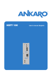
8-channel
24 bit, 96 & 192 kHz, AD/DA Converters
User’s Guide
v1.1 - March 2004
8-channel
24 bit, 96 & 192 kHz, AD/DA Converters
User’s Guide
v1.1 - March 2004
ROSETTA 800 – User’s Guide
APOGEE ELECTRONICS
Warnings
FCC warning
This equipment has been tested and found to comply with the limits for a Class A digital device, pursuant to Part 15 of the FCC rules. These limits are designed to provide reasonable protection against
harmful interference when operated in a commercial environment. This equipment generates, uses,
and can radiate radio frequency energy and, if not installed and used in accordance with the instruction manual, may cause harmful interference to radio communications. Operation of this equipment in
a residential area is likely to cause harmful interference, in which case the user will be required to take
whatever measures necessary to correct the interference at his own expense.
Copyright Notice
The Apogee Rosetta 800 is a computer-based device, and as such contains and uses software in ROMs.
This software, and all related documentation, including this User’s Guide contain proprietary information which is protected by copyright laws. All rights are reserved. No part of the software and its related
documentation may be copied, transferred, or modified. You may not modify, adapt, translate, lease,
distribute, resell for profit or create derivative works based on the software and its related documentation or any part thereof without prior written consent from Apogee Electronics Corporation, U.S.A.
ii
ROSETTA 800 – User’s Guide
APOGEE ELECTRONICS
Registration and Warranty Information
Be sure to register your Rosetta 800, either by filling in the enclosed Registration Card or by
completing the on-line registration form at our Web site: http://www.apogeedigital.com/support/. If
you do so, Apogee can contact you with any update information. As enhancements and upgrades are
developed, you will be contacted at the registration address. Firmware updates are free for the first
year of ownership unless otherwise stated. Please address any inquiries to your dealer or directly to
Apogee at:
APOGEE ELECTRONICS CORPORATION,
3145 Donald Douglas Loop South, Santa Monica, CA 90405, USA.
TEL: (310) 915-1000, FAX: (310) 391-6262
email: [email protected]. Web: http://www.apogeedigital.com/
APOGEE ELECTRONICS CORPORATION warrants this product to be free of defects in material and
manufacture under normal use for a period of 12 months. The term of this warranty begins on the
date of sale to the purchaser. Units returned for warranty repair to Apogee or an authorized Apogee
warranty repair facility will be repaired or replaced at the manufacturer’s option, free of charge.
ALL UNITS RETURNED TO APOGEE OR AN AUTHORIZED APOGEE REPAIR FACILITY MUST
BE PREPAID, INSURED AND PROPERLY PACKAGED, PREFERABLY IN THEIR ORIGINAL BOX.
Apogee reserves the right to change or improve design at any time without prior notification. Design
changes are not implemented retroactively, and the incorporation of design changes into future units
does not imply the availability of an upgrade to existing units.
This warranty is void if Apogee determines, in its sole business judgment, the defect to be the result
of abuse, neglect, alteration or attempted repair by unauthorized personnel.
The warranties set forth above are in lieu of all other warranties, expressed or implied, and Apogee
specifically disclaims any and all implied warranty of merchantability or of fitness for a particular
purpose. The buyer acknowledges and agrees that in no event shall the company be held liable for
any special, indirect, incidental or consequential damages, or for injury, loss or damage sustained by
any person or property, that may result from this product failing to operate correctly at any time.
USA: Some states do not allow for the exclusion or limitation of implied warranties or liability for
incidental or consequential damage, so the above exclusion may not apply to you. This warranty
gives you specific legal rights, and you may have other rights which vary from state to state.
Service Information
The Rosetta 800 contains no user-serviceable components: refer to qualified service personnel for
repair or upgrade. Your warranty will be voided if you tamper with the internal components. If you
have any questions with regard to the above, please contact Apogee.
In the event your Rosetta 800 needs to be upgraded or repaired, it is necessary to contact Apogee
prior to shipping, and a Return Materials Authorization (RMA) number will be assigned. This number
will serve as a reference for you and helps facilitate and expedite the return process. Apogee requires
that shipments be pre-paid and insured — unless otherwise authorized in advance.
IMPORTANT: ANY SHIPMENT THAT IS NOT PRE-PAID OR IS SENT WITHOUT AN RMA
NUMBER WILL NOT BE ACCEPTED.
iii
ROSETTA 800 – User’s Guide
APOGEE ELECTRONICS
Declarations of Conformity
Declaration of Conformity—FCC
Apogee ROSETTA 800
This device complies with Part 15 of the FCC Rules. Operation is subject to the following two conditions:
(1) This device may not cause harmful interference
(2) This device must accept any interference received, including interference that may cause undesired operation.
This equipment has been tested and found to comply with the limits of a Class B digital device, pursuant to Part
15 of the FCC Rules. These limits are designed to provide reasonable protection against harmful inteference in a
residential installation. This equipment generates, uses and can radiate radio frequency energy and, if not installed
and used in accordance with the instructions, may cause harmful interference to radio communications. If this
equipment does cause harmful interference to radio or television reception, which can be determined by turning
the equipment off and on, the user is encouraged to try to correct the interference by one or more of the following
measures:
1. Re-orient or relocate the receiving antenna.
2. Increase the separation between the equipment and receiver.
3. Connect the equipment into an outlet on a different circuit from that to which the receiver is connected.
4. Consult the dealer or an experienced radio/TV technician for help.
NOTE: The use of non-shielded cable with this equipment is prohibited.
CAUTION: Changes or modifications not expressly approved by the manufacturer responsible for compliance
could void the user’s authority to operate the equipment.
Apogee Electronics Corporation, 3145 Donald Douglas Loop South, Santa Monica, CA 90405.
Betty Bennett, CEO.
Industry Canada Notice
This Class B digital apparatus meets all requirements of the Canadian Interference-Causing Equipment Regulations. Cet appareil numérique de la classe B respecte toutes les exigences du Règlement sur le matérial brouilleur
du Canada.
Declaration of Conformity – CE
Apogee Electronics Corporation hereby declares that the product, the Rosetta 800, to which this declaration
relates, is in material conformity with the following standards or other normative documents:
• EN50081-1/EN55022; 1995
• EN50082-1/IEC 801-2, 3, 4; 1992
following the provisions of:
• 73/23/EEC – Low Voltage Directive
• 89/336/EEC – EMC Directive
Declaration of Conformity – Japan
Apogee Electronics Corporation hereby declares that the Rosetta 800, to which this declaration relates, is in material conformity with the VCCI Class A standard.
Declaration of Conformity – Australia
Apogee Electronics Corporation hereby declares that the Rosetta 800 is in material conformity with AN/NZS standard requirements.
iv
ROSETTA 800 – User’s Guide
APOGEE ELECTRONICS
OWNER’S RECORD
The serial number is located on the rear panel of the unit. We suggest you record the
serial number in the space provided below. Refer to it whenever you call an authorized
Apogee Electronics repair facility or the manufacturer. Please be sure to return your completed warranty card immediately!
ROSETTA 800 Serial No.
Purchase Date
Dealer
Phone
Address
CAUTION:
Any changes or modifications not expressly approved by APOGEE ELECTRONICS
CORPORATION could void your authority to operate this equipment under the FCC rules.
Please register this unit by filling in the included registration card, or registering online at
http://www.apogeedigital.com/support/register.php Please read this manual – if you call for
technical support, we’ll assume that you have. There will be a quiz.
v
User’s Guide
Table of Contents
Introduction ......................................................................................................2
Signal Flow Diagram .....................................................................................2
Getting Started Quickly ................................................................................3
Connecting Power .....................................................................................3
Reset ........................................................................................................3
QuickStart ..................................................................................................3
Navigating the Front Panel ......................................................................4-7
Power Switch ............................................................................................4
SAMPLE RATE .........................................................................................4
--- SAMPLE RATE ADVANCED SETTINGS .............................................4
SYNC ........................................................................................................5
--- SYNC ADVANCED SETTINGS .........................................................5-6
LOCK ........................................................................................................6
SOURCE TO DIGITAL OUTS ...................................................................6
SOFT LIMIT ..............................................................................................7
OUTPUT RESOLUTION ...........................................................................7
SIGNAL LEDs ...........................................................................................7
SOURCE TO ANALOG OUT ....................................................................7
Connections on the Rear Panel ...............................................................8
ANALOG IN ...............................................................................................8
ANALOG OUT ...........................................................................................8
ADAT – S/MUX IN .....................................................................................8
ADAT – S/MUX OUT..................................................................................8
OPTION .....................................................................................................8
AES IN/OUT ..............................................................................................8
WORD CLOCK IN .....................................................................................8
WORD CLOCK OUT .................................................................................8
AC IN .........................................................................................................8
Configuration Examples ........................................................................9-12
Internal Adjustments ..................................................................................13
Specifications .................................................................................................14
ROSETTA 800 – User’s Guide
APOGEE ELECTRONICS
Introduction
Apogee Electronics’ Rosetta 800 is a multi-channel Analog and Digital converter designed to provide the highest
quality signal path for all modern digital systems, while setting a new standard of performance at an accessible
price. The following features are included:
•
•
•
•
•
•
Sample rates up to 96kHz, upgradeable to 192kHz.
A wide range of digital interfaces options, including AES, ADAT – S/MUX, plus an Option card providing
future expandability.
Dual stage clock circuitry ensuring stable operation regardless of clock source.
Soft Limit transient limiting circuitry available on all 8 Analog inputs.
UV22HR bit resolution reduction algorithym.
Advanced digital routing.
Signal Flow Diagram
Source to Analog Outs button
To Analog Outputs
ADAT In
OPTION In
AES In
ANALOG In
SOFT LIMIT
A/D
To ADAT Out
Source to Digital Outs button
To OPTION Out
UV22HR
To AES Out
Basic Signal Flow Diagram (without signal) shows Rosetta 800’s
ability to configure two independent signal paths.
2
ROSETTA 800 – User’s Guide
APOGEE ELECTRONICS
Getting Started Quickly
CONNECTING POWER
The Rosetta 800 accepts an AC input of 100 to 240v AC at a frequency of 50
to 60 Hz. Thus, the unit may be connected to virtually any AC power outlet
found worldwide without concern for voltage settings or fuse ratings.
RESET
To reset the Rosetta 800, power up the unit while pressing the SAMPLE RATE
button. This provides a quick method to return to factory default settings when
exploring the unit’s functionality and capabilities.
QUICKSTART
To get started using the Rosetta 800 quickly, please follow these steps:
1)
2)
3)
Connect the AC input, and press the POWER button.
Connect an analog source to the ANALOG INs, connect a digital device to
the appropriate digital I/O (ADAT is used in this example), and connect the
ANALOG OUTs to a monitoring system.
Set SAMPLE RATE to 44.1, set SOURCE TO DIGITAL OUTS to ANALOG,
and set SOURCE TO ANALOG OUTS to ADAT, as shown above.
USING THIS MANUAL
While the regularly scheduled manual runs
in the adjacent text, in-depth explanations,
operational warnings and other digressions
will be presented in these columns.
In this manual, “parameters” are defined
as the characteristics of operation, such as
SAMPLE RATE or SYNC source, and are
capitalized in this manner :
SAMPLE RATE.
“Values” are defined as the choices
available for each parameter – for example,
the parameter SAMPLE RATE has the
values 44.1, 48, and 96. Values are
italicized in this manner: 44.1
“Settings” are defined as the entire set of
parameters and values.
SIGNAL FLOW
The Rosetta 800 offers the possibility to configure two independent signal
paths through the unit. In most cases, the first signal path is configured as
an A/D stage before a digital recording device while the second signal path
is configured as a D/A stage after the recording device.
For example, when the Rosetta 800 is configured to the Quickstart setting
noted above, the following two signal paths are present: 1) the analog
sources to be recorded are connected to the Rosetta analog inputs,
converted to digital and routed to all Rosetta digital outputs including the
ADAT output, connected to an ADAT recording device input; 2) the ADAT
device output is connected to the Rosetta ADAT input, which is converted to
analog and routed to the Rosetta analog outputs, connected to a monitoring
system. Other configuration examples are given in the back of this manual.
3
SYMBOLS:
The exclamation mark alerts
the user to potential pitfalls of
operation.
The musical note indicates indepth explanations.
ROSETTA 800 – User’s Guide
APOGEE ELECTRONICS
Navigating the Front Panel
1
2
1) The Power Switch LED
indcates that the Rosetta 800 is
receiving a proper AC input, and
is in Standby mode. The LED goes out
when the Rosetta 800 is powered on.
2) The 176.4 and 192 values
cannot be selected on the
96kHz version of the Rosetta
800. The unit may be upgraded to
192kHz operation at any time.
3) A different AES format may be
selected for each sample rate
range.
4) When clocking to an AES
input (i.e SYNC is set to AES),
the format must be specified by
selecting a SYNC value of either AES or
AES + DW.
Advanced Settings:
Advanced settings are accessed by pressing and holding one front panel
button while using a second button to modify values. These advanced
settings are described in light gray boxes after the primary description of
each button.
1)POWER SWITCH – The Power Switch may be configured to operate in
the manner best suited to the installation of the unit. For example, if the
Rosetta 800 is installed in a rack with a Master power switch, the unit’s
power switch may be configured appropriately. Please see the section of this
manual entitled “Internal Adjustments” for details. 1
2) SAMPLE RATE – This parameter modifies operation in two distinct ways
according to the value selected:
1) When any of the values 44.1-192 are selected, the unit derives its clock
from an internal crystal and runs at the selected sample rate. 2
2) When EXT is selected, the unit derives its clock from the source
selected by the SYNC parameter; the 44.1-192 LEDs now display the
sample rate of the selected source.
4
SAMPLE RATE Advanced settings: 3
When running at a sample rate between 88.2-192 kHz, the Rosetta 800’s
AES I/O may be configured for Single wire or Double wire operation.
1) Select the desired SAMPLE RATE value.
2) Press and hold SAMPLE RATE to determine the current AES format, as
indicated by the three DW LEDs on the front panel; if DW is on, the AES
format is Double wire; if DW is off, the format is Single wire.
3) While pressing the SAMPLE RATE button, press the SYNC button to
toggle DW (Double Wire) on or off.
4
ROSETTA 800 – User’s Guide
Navigating the Front Panel -
APOGEE ELECTRONICS
continued
3
3) SYNC – When SAMPLE RATE is set to EXT, the SYNC parameter
determines the source of the unit’s clock.
• ADAT – clock is derived from the ADAT input 1-8 with a resultant sample
rate in the 44.1-48kHz range.
• ADAT + S/MUX – clock is derived from S/MUX Input 1-4 with a resultant
sample rate in the 88.2-96kHz range.
• OPTION – clock is derived from the Option Card input.
5
• AES – the AES input is scanned and clock is derived from the first valid
AES signal found. The signal is treated as Single wire format. 6
• AES + DW - the AES input is scanned and clock is derived from the first
valid AES signal found. The signal is treated as Double wire format.
• WC – clock is derived from the Word Clock In connector.
8
SYNC Advanced settings: 7
The Rosetta 800 may be configured to accommodate digital systems whose
word clock signals run at a multiple of the sample rate frequency.
1) To configure the Rosetta 800 to sync to a word clock input of one
frequency while running at a sample rate whose frequency is a multiple of the
word clock:
1)
2)
3)
Connect the word clock signal to the Word Clock In and set SYNC
to WC.
Press and hold the SYNC button to determine the current “target”
sample rate range.
While pressing the SYNC button, press the SAMPLE RATE button
to toggle through the possible “target” ranges. For example, to
sync the Rosetta 800 to a 44.1kHz Word Clock input while running
at 88.2kHz, maintain the SYNC button depressed while pressing
the SAMPLE RATE button the until both the 88.2 and 96 LEDs
light.
2) To configure the Rosetta 800 to sync to another source (internally or other
SYNC values besides WC) and output a Word Clock signal whose frequency
is a multiple of the sample rate frequency:
1) Set the unit to the desired clock source and sample rate
2) Press and hold the SYNC button to determine the current Word
Clock Output frequency range.
3) While pressing the SYNC button, press the SAMPLE RATE
button to toggle through the possible ranges. For example, to run
the Rosetta 800 at an 88.2kHz sample rate while outputting a
44.1kHz word clock, set the SAMPLE RATE to 88.2, maintain the
SYNC button depressed while pressing the SAMPLE RATE button
until both 44.1 and 48 LEDs light.
5
5) If no Option card is present,
the Option value may not be
selected.
6) When clocking to an AES
input, the AES format must be
specified by selecting a SYNC
value of either AES or AES + DW, not via
the SAMPLE RATE Advanced settings.
7) The Word Clock Out will
always be the same frequency
as the Word Clock In.
8) A different Word Clock
configuration may be set for
each sample rate range.
ROSETTA 800 – User’s Guide
APOGEE ELECTRONICS
Navigating the Front Panel -
continued
4
5
9) The clock circuitry of a
typical D-to-A converter must
be designed as a compromise
between the ability to attenuate input
signal jitter and the ability to accept any
bitstream, regardless of it’s stability. The
more the clock is allowed to track timing
variations of the input, the more jitter
remains in the clock at the conversion
stage, with the degradation of conversion
quality as a result. The ROSETTA
800’s Dual Stage Clock overcomes
this compromise by employing one
clock stage to accept the bitstream
and store bits in a buffer, and a second
stage to clock bits out of the buffer to
the conversion stage. The first stage is
optimized to track timing variations of the
input, while the second stage is optimized
to attenuate jitter and ensure that
conversion takes place with the lowest
jitter clock possible.
10) When the Rosetta 800 is
running at the 176.4 – 192
kHz sample rate range, neither
ADAT nor ADAT + S/MUX may be
selected.
4) LOCK - These LEDs indicate the Lock status of the Rosetta 800’s dual stage
clock. Two levels of lock precision are displayed, Wide and Narrow. 9
5) SOURCE TO DIGITAL OUTS – This parameter configures the first of two
available signal paths by selecting the input source(s) routed to ALL digital
outputs. A total of eight channels may be routed, either entirely from one source
or from one digital source and the Analog source. To select a digital source and
the Analog source simultaneously, toggle through the entire set of possible values
until both desired SOURCE TO DIGITAL OUTS values are lit. Assignment of each
of the 8 channels to a digital or analog source is accomplished (by pairs) with the
Advanced settings noted below: 10 11 12
SOURCE TO DIGITAL OUTS Advanced settings:
When two sources have been selected, the following Advanced settings
become available:
• To display current routing:
1) Press and hold the SOURCE TO DIGITAL OUTS button to
display the current configuration of analog and digital sources as
indicated by the DIGITAL OUT LEDs. If the DIGITAL OUT LED is
on, the source for the corresponding channel pair is the Analog
input; if the DIGITAL OUT LED is off, the source is the selected
digital input. For example, in FIGURE 1, channels 1-2 and 7-8 are
set to the Analog source, while channels 3-4 and 5-6 are set to the
ADAT source.
FIGURE 1
• To modify routing:
1) While pressing the SOURCE TO DIGITAL OUTS button, press the
SOFT LIMIT button to select the pair of channels to be modified;
the selected pair is indicated by the flashing A/D OVER LEDs.
2) While pressing the SOURCE TO DIGITAL OUTS button, press the
OUTPUT RESOLUTION button to toggle the selected pair between
ANALOG and the selected digital source.
6
ROSETTA 800 – User’s Guide
APOGEE ELECTRONICS
Navigating the Front Panel -
continued
6
7
8
9
6) SOFT LIMIT – This button engages Soft Limit, Apogee’s proprietary transient
limiting circuitry, on all 8 Analog inputs. Soft Limit transparently rounds transient
spikes in a manner similar to analog tape, allowing several more dB of signal to be
recorded onto the digital medium.
11) A blinking digital source
LED indicates that the
selected source is not
synchronous with the unit’s clock source.
7) OUTPUT RESOLUTION – This button engages UV22HR, Apogee’s proprietary
bit-resolution reduction algorithm, on all digital outputs. UV22HR should be applied
when 16-bit digital devices are connected to the Rosetta 800’s Digital outputs, such
as DAT recorders or CD burners. By adding an algorithmically generated, inaudible
concentration of energy at around 22kHz, UV22HR preserves 24-bit resolution in a
16-bit digital signal. 13
12) The S/MUX and DW LEDs
located in the SOURCE TO
DIGITAL OUTS value list are
indicators only and cannot be selected.
8) SIGNAL LEDs
1) A/D OVER – These red LEDs indicate the occurrence of digital OVERs
(defined as 3 consecutive samples at full scale) in the A/D converter section.
2) DIGITAL OUT – These LEDs indicate the digital level of the source(s) routed
to the digital outputs.
3) ANALOG OUT – These LEDs indicate the digital level of the source(s) routed
to the analog outputs.
9) SOURCE TO ANALOG OUT – This parameter configures the second
available signal path by selecting the input source(s) routed to the analog outputs.
A total of eight channels may be routed, either entirely from one source or from
one digital source and the analog source. To select a digital source and the
Analog source simultaneously, toggle through the entire set of possible values
until both desired SOURCE TO ANALOG OUT values are lit. Assignment of each
of the 8 channels to a digital or analog source is accomplished (by pairs) with the
Advanced settings listed below:
SOURCE TO ANALOG OUT Advanced settings:
When two sources have been selected, the following Advanced settings become
available:
• To display current routing:
1) Press and hold the SOURCE TO ANALOG OUT button to display the current
configuration of analog and digital sources as indicated by the ANALOG
OUT LEDs. If the ANALOG OUT LED is on, the source for the corresponding
channel pair is the Analog input; if the ANALOG OUT LED is off, the source is
the selected digital input.
• To modify routing:
1) While pressing the SOURCE TO ANALOG OUT button depressed, press the
SOFT LIMIT button to select the pair of channels to be modified; the selected
pair is indicated by the flashing A/D OVER LEDs.
2) While maintaining the SOURCE TO ANALOG OUT button depressed,
press the OUTPUT RESOLUTION button to toggle the selected pair between
ANALOG and the selected digital source.
7
13) OUTPUT RESOLUTION
can be set to 16-Bit UV22HR
only when SAMPLE RATE is
set to the 44.1-48 kHz range.
ROSETTA 800 – User’s Guide
APOGEE ELECTRONICS
Connections on the Rear Panel
5
4
3
1
2
1)
6
ANALOG IN – This DB-25 connection
accepts 8 balanced line-level analog inputs
at a nominal level of +4 dBu =16 dBFs
7
8
DB-25 pinout for ANALOG IN/OUT
8
7
6
5
4
3
2
1
G C H G C H G C H G C H G C H G C H G C H G C H
2)
ANALOG OUT - This DB-25 connection
provides 8 balanced line-level analog outputs
at a nominal level of –16 dBFs = +4 dBu.
13
12
25
11
24
9
10
23
To set the Analog In/Out to a different
calibration level, please see the
section of this manual entitled “Internal
Adjustments”. The pinout of the Analog
In/Out connectors is compatible with the
Tascam analog cable standard.
22
8
21
7
20
6
19
5
18
4
17
3
16
2
15
1
14
H=HOT C=COLD G=GROUND
3)
ADAT – S/MUX IN – These Toslink connections accept ADAT or S/MUX format optical inputs according to
the front panel configuration. When connecting ADAT signals, use the Toslink connection labeled IN 1-8.
When connecting S/MUX signals, use connector “1-4” for the first four channels and connector “5-8” for the
second four channels.
4)
ADAT – S/MUX OUT - These Toslink connections provide ADAT or S/MUX format optical outputs
according to the front panel configuration. When connecting ADAT signals, both Toslink connections
provide a duplicate output. When connecting S/MUX signals, use connector “1-4” for the first four channels
and connector “5-8” for the second four channels.
5)
OPTION - This slot is reserved for Option
cards, which provide additional input/output
formats, such as FireWire.
6)
DB-25 pinout for AES IN/OUT
7,8
out
AES IN/OUT – This DB-25 connection
accepts 8 channels of AES/EBU digital
input and provides 8 channels of AES/
EBU digital output. When the AES I/O
has been configured for double wide
operation, only the first 4 channels of input
and output are available. The pinout of
the AES IN/OUT connection is compatible
with the Yamaha AES cable standard.
G G G G
13
12
25
G G
11
24
9
10
23
22
5,6
out
3,4
out
1,2
out
7,8
in
5,6
in
3,4
in
1,2
in
C H C H C H C H C H C H C H C H
8
21
7
20
6
19
5
18
4
17
3
16
2
15
1
14
H=HOT C=COLD G=GROUND
7)
WORD CLOCK IN - This BNC connection
accepts a TTL Logic clock signal. The Word Clock In is un-terminated.
8)
WORD CLOCK OUT - This BNC connection provides a TTL Logic clock signal output.
9)
AC IN - This IES connection accepts an AC input of 100 to 240 VAC at a frequency of 50 to 60 Hz.
8
9
ROSETTA 800 – User’s Guide
APOGEE ELECTRONICS
Configuration Examples
CONFIGURATION #1 :
To configure the Rosetta 800 to function as an A/D and D/A converter for an AES digital device,
make the FRONT PANEL SELECTIONS and REAR PANEL CONNECTIONS as follows:
FRONT PANEL SELECTIONS
Select “ANALOG”
as SOURCE TO DIGITAL OUTS
Select “AES”
as SOURCE TO DIGITAL OUTS
REAR PANEL CONNECTIONS
ANALOG IN
From mixing console
or other analog source
ANALOG OUT
To monitor system
AES IN/OUT
from/to AES device
ie. CD burner, DAT machine,
hard disk recorder, etc.
SEE FLOW DIAGRAM ON PG. 12
9
ROSETTA 800 – User’s Guide
APOGEE ELECTRONICS
Configuration Examples -
continued
CONFIGURATION #2 :
To configure the Rosetta 800 to convert an ADAT input to AES for recording on an AES digital device, while monitoring
the AES device output via the ANALOG OUTs, make the FRONT PANEL SELECTIONS and REAR PANEL
CONNECTIONS as follows:
FRONT PANEL SELECTIONS
Select “ADAT”
as SOURCE TO DIGITAL OUTS
Select “AES”
as SOURCE TO ANALOG OUT
REAR PANEL CONNECTIONS
AES IN/OUT
from/to AES device
ie. CD burner, DAT machine,
hard disk recorder, etc.
ANALOG OUT
To monitor system
ADAT IN
from ADAT device ie.
computer based DAW, MDM,
DAT machine, etc.
10
ROSETTA 800 – User’s Guide
APOGEE ELECTRONICS
Configuration Examples -
continued
CONFIGURATION #3 (advanced settings) :
To configure the Rosetta 800 to accept 6 channels of analog input and 2 channels of AES input for recording on
an ADAT digital device while monitoring the ADAT device output via the ANALOG OUTs, make the FRONT PANEL
SELECTIONS and REAR PANEL CONNECTIONS as follows:
FRONT PANEL SELECTIONS
Select “AES” and “ANALOG”
as SOURCE TO DIGITAL OUTS
(refer to “SOURCE TO DIGITAL OUTS
Advanced Settings” on page 6)
Select “ADAT”
as SOURCE TO ANALOG OUT
REAR PANEL CONNECTIONS
AES IN/OUT
from/to AES device
ie. CD burner, DAT machine,
hard disk recorder, etc.
ANALOG IN
From mixing console
or other analog source
ANALOG OUT
To monitor system
ADAT IN/OUT
from ADAT device ie.
computer based DAW, MDM,
DAT machine, etc.
SEE FLOW DIAGRAM ON PG. 12
11
ROSETTA 800 – User’s Guide
APOGEE ELECTRONICS
Configuration Examples -
continued
FLOW DIAGRAM CONFIGURATION #1:
Source to Analog Outs button
To Analog Outputs
ADAT In
OPTION In
AES In
ANALOG In
SOFT LIMIT
A/D
To ADAT Out
Source to Digital Outs button
To OPTION Out
UV22HR
To AES Out
AES DEVICE
FLOW DIAGRAM CONFIGURATION #3 (advanced settings) :
Source to Analog Outs button
To Analog Outputs
ADAT In
OPTION In
AES In
ANALOG In
SOFT LIMIT
A/D
To ADAT Out
Source to Digital Outs button
To OPTION Out
UV22HR
To AES Out
ADAT DEVICE
12
ROSETTA 800 – User’s Guide
APOGEE ELECTRONICS
Internal Adjustments
ANALOG INPUT/OUTPUT CALIBRATION
Calibration levels for the Analog Inputs and Outputs are set with internal jumpers. A “block” of 6 jumpers offers 3
level settings for each input and output channel. The locations of these jumpers are indicated in FIGURE 3.
FIGURE 3
FIGURE 4 depicts the reference
analog and digital levels obtained
when applying a shunt to each
pair of jumpers. For example,
when a shunt is applied to the
middle pair of each input and
output “block”, a +4 dBu analog
input results in a –16 dBFs digital
output, while a –16dBFs digital
input results in a +4 dBu analog
output.
JUMPER
(as seen from front)
ANALOG
Reference Level
DIGITAL
Reference Level
-10 dBV
-13 dBfs
+4 dBu
-16 dBfs
+4 dBu
-20 dBfs
FIGURE 4
POWER SWITCH CALIBRATION
JUMPER P3
(as seen from front)
DESCRIPTION
When AC power is applied to the input, the unit does not
power up immediately; to power on the unit,the POWER
button must be pressed.
When AC power is applied to the input, Rosetta 800 powers
on immediately; nevertheless, the POWER switch is
functional.
FIGURE 5
13
ROSETTA 800 – User’s Guide
APOGEE ELECTRONICS
Features and Specifications
• 8 channels of premium 24-bit AD/DA conversion
• Sample rates up to 96k with optional 192k upgrade
• 8 channels of AES, ADAT I/O
• Optional Firewire card for compatibility with OS X, and Windows XP
• “Soft Limit” for maximum digital level without overs
• “UV22HR” for superior dither to 16-bit
INPUTS:
• Analog In 1-8: Balanced, DSUB connector
• AES in: x 4, transformer balanced, DSUB connector
• Optical - ADAT/SMUX In: Toslink
• WC In: BNC 75 ohm
OUTPUTS:
• Analog Out 1-8: Balanced, DSUB connector.
• AES Out: x 4, transformer balanced, DSUB connector
• Optical - ADAT/SMUX Out: Toslink
• WC Out: BNC 75 ohm
SPECS:
• Sample rates: 44.1 - 48k, 88.2 - 96k (+/-10%);
176.4 - 192k (optional)
• Frequency response: 10 –20k (+/- 0.2 dB) at 44.1k
• Analog max levels: +6dBV, +20dBu, +24dBu max
(set by internal jumper)
• Dynamic range: 114 dB A weighted (AD + DA)
• THD+N: -105 dB (AD), -103 dB (DA)
• Power: 90-250 VAC, 50-60Hz, 45Watt
Due to on-going development Apogee reserves the right to change all information and specifications without notice.
14
ROSETTA 800 USER’S GUIDE - v1.1 - March 2004
Text conceived and delivered by: Roger Robindore
Graphics and product illustration by: Sean McArthur