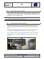
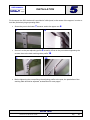
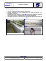
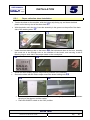
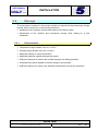
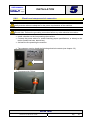
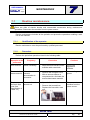
1
NEO LT DIGIT L SUPER TRIM 165 - 280 - 340 - 520 I MANUALE D’USO GB USER'S MANUAL SUPER TRIM 165 / 280 / 340 / 520 MANUALE D’USO I GB USER’S MANUAL Code NLT.QG-16-2011-4S-it/gb Printed in Italy USOIT-GB- SUPER-4S.DOC NEOLT 2011 MANUALE D’USO NEOLT s.p.a SUPER TRIM 165 / 280 / 340 / 520 Le istruzioni in originale sono quelle redatte in lingua italiana. Revisioni REVISIONE DATA NOTE VERSIONE 04 11/04/2011 Prima edizione NLT.QG-16-2011-4S-IT I MANUALE D’USO Edizione - ITALIANO Cod. NLT.QG-16-2011-2S-IT Stampato in Italia NEOLT 2011 USOIT-SUPER-4S.DOC TEXTILE SUPER TRIM VERSIONE: NLT.QG-16-2011-4S-IT Pag. 2 MANUALE D’USO INDICE DEI CONTENUTI NEOLT s.p.a 1.1 1.2 1.3 1.4 1.4.1 1.4.2 1.5 1.6 1.7 1.8 1.9 1.10 1.11 1.11.1 1.11.2 1.11.3 Dati del manuale...................................................................................... 5 Destinatari ............................................................................................... 5 Proprietà delle informazioni ..................................................................... 5 Convenzioni ............................................................................................. 6 Convenzioni terminologiche .................................................................... 6 Convenzioni tipografiche ......................................................................... 6 Dati di identificazione del fabbricante ...................................................... 7 Dati di identificazione della macchina...................................................... 7 Dichiarazione CE di conformità ............................................................... 8 Garanzia .................................................................................................. 8 Assistenza ............................................................................................... 8 Utilizzo del manuale ................................................................................ 9 Descrizione della macchina ..................................................................... 9 Usi previsti ............................................................................................... 9 Usi non previsti ...................................................................................... 10 Struttura della macchina ........................................................................ 11 2.1 2.1.1 2.2 2.3 2.3.1 2.3.2 2.4 2.5 2.5.1 Criteri di sicurezza ................................................................................. 12 Specifiche modulo LASER .................................................................... 12 Qualifica del personale .......................................................................... 13 Protezioni............................................................................................... 13 Ripari ..................................................................................................... 13 Dispositivi di sicurezza attivi .................................................................. 14 Zone pericolose rischi residui ................................................................ 14 Rumore .................................................................................................. 15 Informazione sui pericoli da rumore ...................................................... 15 3.1 3.2 Specifiche tecniche................................................................................ 16 Dati di alimentazione ............................................................................. 16 4.1 TASTIERA E COMANDI........................................................................ 17 5.1 5.2 5.2.1 5.2.2 5.3 5.3.1 5.4 5.5 5.5.1 5.6 5.6.1 5.6.2 5.6.3 Qualifica dell’operatore .......................................................................... 20 Trasporto ............................................................................................... 20 Condizione di trasporto.......................................................................... 20 Verifica dei danni arrecati durante il trasporto ....................................... 21 Assemblaggio ........................................................................................ 22 Montaggio telo porta carta ..................................................................... 26 Montaggio porta rotolo........................................................................... 28 Immagazzinamento ............................................................................... 29 Caratteristiche ....................................................................................... 29 Collocazione .......................................................................................... 30 Caratteristiche della zona di collocazione ............................................. 30 Allacciamento elettrico e aria compressa .............................................. 31 Collaudo ................................................................................................ 32 TEXTILE SUPER TRIM VERSIONE: NLT.QG-16-2011-4S-IT Pag. 3 MANUALE D’USO INDICE DEI CONTENUTI NEOLT s.p.a 6.1 6.1.1 6.1.2 6.2 6.2.1 6.2.2 6.2.3 6.2.4 6.2.5 6.2.6 6.2.7 Qualifica dell’operatore .......................................................................... 33 Posto di lavoro ....................................................................................... 33 Accensione della macchina ................................................................... 33 USO ....................................................................................................... 33 Programmazione ................................................................................... 33 Programmazione delle memorie ............................................................ 34 Inserimento e procedura di taglio in modalità “Auto” ............................. 37 Inserimento e procedura di taglio in modalità “Manu” ........................... 39 Caratteristiche supporti da tagliare ........................................................ 41 Regolazione piano di lavoro posteriore ................................................. 41 Regolazione raggio LASER ................................................................... 42 7.1 7.1.1 7.1.2 7.2 Manutenzione ordinaria ......................................................................... 43 Qualifica dell’operatore .......................................................................... 43 Procedura .............................................................................................. 43 Manutenzione straordinaria ................................................................... 45 8.1 8.2 8.2.1 Qualifica dell’operatore .......................................................................... 46 Disattivazione della macchina ............................................................... 46 Procedura .............................................................................................. 46 A.1 Dichiarazione di conformità CE ............................................................. 47 TEXTILE SUPER TRIM VERSIONE: NLT.QG-16-2011-4S-IT Pag. 4 MANUALE D’USO INFORMAZIONI GENERALI NEOLT s.p.a 1.1 Dati del manuale Manuale di istruzioni. Codice manuale: 1.2 TAGLIERINA NLT.QG-16-2011-4S-IT Destinatari Manuale di istruzioni. Trasportatore. Installatore. Utilizzatore. Manutentore. Demolitore. Per ulteriori dettagli sui destinatari di questo manuale, fare riferimento a 2.2 Qualifica del personale. 1.3 Proprietà delle informazioni Questo manuale contiene informazioni di proprietà riservata. Tutti i diritti sono riservati. Questo manuale non può essere riprodotto o fotocopiato, in tutto o in parte, senza il preventivo consenso scritto di NEOLT S.p.A. L'uso di questo materiale documentale è consentito solo al cliente a cui il manuale è stato fornito come corredo della macchina, e solo per scopi di installazione, uso e manutenzione della macchina a cui il manuale si riferisce. NEOLT S.p.A. dichiara che le informazioni contenute in questo manuale sono congruenti con le specifiche tecniche e di sicurezza della macchina a cui il manuale si riferisce. Il fabbricante non si assume alcuna responsabilità per danni diretti o indiretti a persone, cose o animali domestici conseguenti all'uso di questo materiale documentale o della macchina in condizioni diverse da quelle previste. NEOLT S.p.A. si riserva il diritto di apportare modifiche o miglioramenti senza preavviso a questo materiale documentale e alle macchine, eventualmente anche alle macchine commercializzate dello stesso modello di quella a cui si riferisce questo manuale ma con numero di matricola differente. Le informazioni contenute in questo manuale si riferiscono in particolare alla macchina specificata in 1.6 Dati di identificazione della macchina. TEXTILE SUPER TRIM VERSIONE: NLT.QG-16-2011-4S-IT Pag. 5 MANUALE D’USO INFORMAZIONI GENERALI NEOLT s.p.a 1.4 Convenzioni 1.4.1 Convenzioni terminologiche Macchina: indica la macchina specificata in 1.6 Dati di identificazione della macchina. Telaio: struttura portante della macchina. Personale qualificato: persone che, per la loro competenza ed esperienza, nonché le conoscenze delle relative norme, prescrizioni di sicurezza e condizioni di servizio, sono in grado di riconoscere ed evitare ogni possibile pericolo per le persone e ogni possibile danno al materiale lavorato e alla macchina. Le descrizioni di direzione, senso e posizione (destra della macchina, sinistra della macchina) si riferiscono alla posizione dell'operatore di fronte alla macchina. 1.4.2 Convenzioni tipografiche Testo in corsivo: indica il titolo di un capitolo, una sezione, una sottosezione, un paragrafo, una tabella o una figura di questo manuale, o di un'altra pubblicazione di riferimento. 1 A (numero generico d'esempio): rappresentazione simbolica di un dispositivo di comando o di segnalazione. (lettera generica d'esempio): rappresentazione simbolica di una parte della macchina. Le note contengono importanti informazioni, evidenziate al di fuori del testo cui si riferiscono. Le indicazioni di pericolo indicano quelle procedure la cui mancata, osservanza può produrre danni fisici all'operatore. Il produttore non si assume alcuna responsabilità per eventuali danni alle persone derivate dalla mancanza osservanza di tali indicazioni. Le indicazioni di attenzione indicano quelle procedure la cui mancata osservanza può produrre danni al prodotto o alle apparecchiature ad esse collegate. Il produttore non si assume alcuna responsabilità per eventuali danni a cose derivati dalla mancata osservanza di tali indicazioni. TEXTILE SUPER TRIM VERSIONE: NLT.QG-16-2011-4S-IT Pag. 6 MANUALE D’USO INFORMAZIONI GENERALI NEOLT s.p.a 1.5 Dati di identificazione del fabbricante neolt S.p.A. Via G. Galilei 8 24036 Ponte San Pietro (BG) - ITALY Tel. 035/468811 Fax 035/468886 http://www.neolt.it E-mail.: [email protected] 1.6 Dati di identificazione della macchina Denominazione Taglierina refilatrice Modello SUPER TRIM xxx PNE Numero di matricola Anno di costruzione Peso TEXTILE SUPER TRIM VERSIONE: NLT.QG-16-2011-4S-IT Pag. 7 MANUALE D’USO INFORMAZIONI GENERALI NEOLT s.p.a 1.7 Dichiarazione CE di conformità Nell'Allegato A Dichiarazione di conformità CE è riportata una riproduzione della dichiarazione CE di conformità della macchina 1.8 Garanzia NEOLT S.p.A. garantisce la macchina per un periodo di 1 anno. Sono escluse dalla garanzia le parti soggette a normale usura o consumo. La garanzia è limitata alla sostituzione o/a riparazione dei pezzi per accertato difetto del materiale. L'esame dei difetti e delle cause viene eseguito presso NEOLT S.p.A. La garanzia viene annullata in caso di macchina utilizzata per usi non previsti, in caso di utilizzo negligente o eccessivo, in caso di utilizzo di parti di ricambio non originali e in caso di mancata osservanza delle indicazioni di questo manuale. In nessun caso l'acquirente può pretendere la risoluzione del contratto, un risarcimento danni o la proroga della garanzia. La garanzia è applicabile e valida solo per l'acquirente di origine e solo per il periodo (durante il periodo di garanzia) in cui l'attrezzatura è in possesso dell'acquirente di origine NEOLT S.p.A. non si assume alcuna responsabilità per eventuale pubblicità negativa, o mancati introiti, dovuti al malfunzionamento , tecnico o meccanico, del prodotto in uso o in esposizione. Il corretto e sicuro funzionamento della macchina è assicurato solo se è utilizzata in accordo con quanto indicato nel manuale e nella documentazione di accompagnamento. La NEOLT S.p.A. respinge ogni responsabilità per danni a persone o cose derivanti da un uso improprio della macchina o da modifiche non preventivamente autorizzate dal fabbricante stesso. 1.9 Assistenza NEOLT S.p.A. fornisce a richiesta un servizio di assistenza per l'installazione e la manutenzione della macchina. Per la richiesta di assistenza o informazioni varie, rivolgersi al seguente indirizzo; neolt S.p.A. Via G. Galilei 8 24036 Ponte San Pietro (BG) – ITALY Tel. 035/468811 / Fax 035/468886 Web site: http://www.neolt.it / E-mail.: [email protected] TEXTILE SUPER TRIM VERSIONE: NLT.QG-16-2011-4S-IT Pag. 8 MANUALE D’USO INFORMAZIONI GENERALI NEOLT s.p.a 1.10 Utilizzo del manuale Leggere attentamente i capitoli Informazioni generali, Informazioni sulla sicurezza, Caratteristiche della macchina. Per qualsiasi operazione di trasporto, installazione, utilizzo, manutenzione e demolizione consultare il corrispondente capitolo. Questo manuale e la documentazione allegata devono essere conservati per tutta la vita tecnica della macchina in modo da essere facilmente reperibili in caso di necessità. In caso di vendita della macchina usata, questa dovrà essere venduta completa del presente manuale e della documentazione allegata. 1.11 Descrizione della macchina 1.11.1 Usi previsti La macchina va utilizzata esclusivamente per il taglio dei supporti e grammature consentite (max. spessore consentito 7 mm.). Poiché la macchina è costituita da gruppi fisicamente distinti ed autonomi, l’uso proprio di macchina si identifica nel funzionamento anche di una sola parte. Modalità di utilizzo previste L'installazione e la manutenzione straordinaria della macchina devono essere effettuate da personale qualificato. La macchina è stata realizzata per essere utilizzata in un ambiente con le seguenti caratteristiche: Protezione dagli agenti atmosferici. Illuminazione adeguata. Intervallo di temperatura ammesso: da 18°C a 35°C. Intervallo di umidità relativa ammesso: dal 30 % al 80 %. Alimentazione elettrica con le seguenti caratteristiche: - Tensione e frequenza monofase: 230V/240V 50Hz - Corrente assorbita: max.1,5A (mod.280) max.2A (mod.280/340) max.3A (mod.520) - Tensione e frequenza monofase: 110V/60Hz - Corrente assorbita: max.2,5A (mod.280) max.3A (mod.280/340) max.4A (mod.520) Pressione aria 6 bar. TEXTILE SUPER TRIM VERSIONE: NLT.QG-16-2011-4S-IT Pag. 9 MANUALE D’USO INFORMAZIONI GENERALI NEOLT s.p.a 1.11.2 Usi non previsti Sono usi non previsti tutti gli usi non esplicitamente indicati in 1.10.1 Usi previsti, in particolare: Qualsiasi impiego diverso da quello da cui la macchina è stata costruita rappresenta una condizione anomala e può recare danno alla struttura della macchina. Il suo impiego senza le protezioni e salvaguardie in dotazione alla macchina: in particolare senza i carter fissi che impediscono l’accesso agli equipaggiamenti interni. Il mancato rispetto delle procedure riportate in questo manuale con particolare riferimento a quelle di manutenzione e riparazione. L’impiego della macchina in ambiente a rischio d’incendio e di esplosione in quanto essa non è equipaggiata con componenti di tipo antideflagrante. Utilizzo in atmosfera esplosiva. Utilizzo in atmosfera infiammabile. TEXTILE SUPER TRIM VERSIONE: NLT.QG-16-2011-4S-IT Pag. 10 MANUALE D’USO INFORMAZIONI GENERALI NEOLT s.p.a 1.11.3 A B C D E F G I L M O P Q Struttura della macchina La macchina è formata dalle seguenti parti: Piano di inserimento Plexiglas di protezione F Supporto Telo raccogli carta Tasti controllo G Interruttore ON/OFF R Presa di alimentazione Interruttore d’emergenza Carter posteriore superiore Lamiera di protezione R T Tracciatore laser Barra premi-foglio Regolazione pressione lama Rubinetto e innesto aria compressa Portarotolo Opzionale E O C A I B D M P O L Q T TEXTILE SUPER TRIM VERSIONE: NLT.QG-16-2011-4S-IT Pag. 11 MANUALE D’USO NEOLT s.p.a 2.1 INFORMAZIONI SULLA SICUREZZA Criteri di sicurezza Nella progettazione e nella costruzione di questa macchina sono stati adottati i criteri e gli accorgimenti adatti a soddisfare i requisiti essenziali di sicurezza previsti dalla normative. L'accurata analisi dei rischi svolta dal fabbricante ha consentito di eliminare la maggior parte dei rischi connessi alle condizioni di uso della macchina, sia previste che ragionevolmente prevedibili. La documentazione completa delle misure adottate ai fini della sicurezza è contenuta nel fascicolo tecnico della macchina, depositato presso il fabbricante. Il fabbricante raccomanda di attenersi scrupolosamente alle istruzioni, procedure e raccomandazioni contenute in questo manuale ed alla vigente legislazione sulla sicurezza nell'ambiente di lavoro, anche per l'utilizzo dei dispositivi di protezione previsti, sia integrati nella macchina che individuali. NEOLT S.p.A. non si assume alcuna responsabilità per eventuali danni a persone, animali domestici o cose derivanti dal mancato rispetto delle norme di sicurezza e delle raccomandazioni contenute nella documentazione fornita. 2.1.1 Specifiche modulo LASER Laser classificazione Normativa Emissione CEI,76-2 CEI EN 60825-1-1995 laser classe 3 A. < 5mW Sicurezza I laser di classe 3 A, nell’intervallo di lunghezza d’onda tra 400 e 700 nm. non richiedono particolari blocchi di sicurezza o chiavi per il loro funzionamento. TEXTILE SUPER TRIM VERSIONE: NLT.QG-16-2011-4S-IT Pag. 12 MANUALE D’USO NEOLT s.p.a 2.2 INFORMAZIONI SULLA SICUREZZA Qualifica del personale Fase della vita tecnica della macchina Qualifica operatore responsabile Trasporto Trasporti qualificati Installazione Personale qualificato Uso Personale qualificato Manutenzione ordinaria Personale qualificato Manutenzione straordinaria Tecnici incaricati da NEOLT S.p.A. Demolizione Personale qualificato 2.3 Protezioni NEOLT S.p.A. non si assume alcuna responsabilità per eventuali danni a persone, animali domestici o cose derivanti dal mancato rispetto delle norme di sicurezza e delle raccomandazioni contenute nella documentazione fornita. La manomissione delle protezioni e dei dispositivi di sicurezza causa rischi per gli utilizzatori della macchina e per altre persone esposte. NEOLT S.p.A. declina ogni responsabilità in casi di eventuali danni a persone, animali domestici o cose, causati dalla manomissione delle protezioni. 2.3.1 Ripari La macchina è dotata dei seguenti ripari. Protezioni mobili interbloccate: Carter anteriori, posteriore e laterali Lamiere di protezione ventilatori Lamiere di protezione inferiori Plexiglas TEXTILE SUPER TRIM VERSIONE: NLT.QG-16-2011-4S-IT Pag. 13 MANUALE D’USO NEOLT s.p.a 2.3.2 INFORMAZIONI SULLA SICUREZZA Dispositivi di sicurezza attivi Ripari interbloccati (lamiera posteriore, plexiglas e lamiera di protezione). Funzionamento di sicurezza indiretta - Circuito Equipotenziale di protezione. La macchina è dotata di pulsante di arresto Stop/Emergenza (Fig. 2.1). Sensori fine corsa carrello. 2.4 Fig. 2. 1 Zone pericolose rischi residui E' zona pericolosa qualsiasi zona in prossimità della macchina nella quale una persona è esposta a rischio di lesioni o danni alla salute. In particolare fare attenzione alle mani durante le operazioni di taglio. Durante alcune procedure di intervento sulla macchina, di volta in volta segnalate in questo manuale, esistono dei rischi residui per l'operatore. I rischi residui possono essere eliminati seguendo attentamente le procedure indicate in questo manuale e adottando i dispositivi di protezione individuale indicati. Come esempio: Posizionare il cavo di alimentazione in modo che non sia calpestato o rovinato. Non mettere il cavo di alimentazione dove può essere danneggiato. Operazioni di manutenzione e servizio devono essere effettuate solo dal servizio tecnico autorizzato dal produttore. Fare attenzione alle etichette di pericolo sulla taglierina (Fig. 2.2). Evitare le esposizioni dirette sulla sorgente LASER durante le operazioni. Attenzione l’esecuzione di procedure o di interventi sul LASER diversi da quelli specificati possono essere causa di esposizioni a livelli di radiazione pericolosi. Fig. 2. 2 NEOLT S.p.A. non si assume alcuna responsabilità per eventuali danni a persone, animali domestici o cose derivanti dal mancato rispetto delle precauzioni prescritte o dal mancato utilizzo dei DPI prescritti. TEXTILE SUPER TRIM VERSIONE: NLT.QG-16-2011-4S-IT Pag. 14 MANUALE D’USO NEOLT s.p.a 2.5 INFORMAZIONI SULLA SICUREZZA Rumore Dati sul rumore aereo prodotto da una macchina identica a quella indicata in questo manuale, misurati secondo le indicazioni della "Direttiva Macchine" (2006/42/CE e successive modifiche). Livello medio di pressione acustica continuo equivalente ponderato, intorno alla macchina alla distanza di un metro: Durante la fase di regime: inferiore a 60 db. 2.5.1 Informazione sui pericoli da rumore I livelli di emissione del rumore aereo indicati non implicano necessariamente livelli di esposizione sicuri per il lavoratore. I livelli di esposizione del lavoratore sono ovviamente correlati ai livelli di emissione della macchina, tuttavia anche altri fattori influenzano i livelli di esposizione del lavoratore: durata dell'esposizione, caratteristiche dell'ambiente e presenza di altre macchine. I livelli di emissione della macchina permettono comunque all'utilizzatore di effettuare una stima dei pericoli dovuti al rumore aereo. Un uso continuativo della macchina e dei macchinari prevedibilmente presenti nell'ambiente di installazione potrebbe causare un'elevata esposizione quotidiana personale al rumore. Se l'esposizione quotidiana personale può essere pari o superiore a 85 dB(A) è consigliabile utilizzare DPI (cuffia protettiva, tappi protettivi, ...). Se l'esposizione quotidiana personale può essere pari o superiore a 90 dB(A) è obbligatorio utilizzare DPI (cuffia protettiva, tappi protettivi, ...). Per informazioni su altre misure di protezione da adottare, in Italia riferirsi al Decreto Legislativo N. 277, del 15.08.91. TEXTILE SUPER TRIM VERSIONE: NLT.QG-16-2011-4S-IT Pag. 15 MANUALE D’USO NEOLT s.p.a 3.1 CARATTERISTICHE DELLA MACCHINA Specifiche tecniche 165 280 340 520 Spessore max. di taglio (mm) 7 7 7 7 Lunghezza utile di taglio (cm) 165 280 340 520 Lunghezza (cm) 250 366 421 607 Larghezza (cm) 58 58 58 58 Altezza c/supporto (cm) 112 112 112 112 Altezza piano di lavoro (cm) 91 91 91 91 Peso totale (kg) 105 150 200 300 - - - opzionale MODELLO Porta rotolo Alimentazione 230V/50Hz Consumo 270W 330W Pressione aria 6/7 Bar Velocità carrello 3.2 440W max. 50cm/sec - min. 2cm/sec Dati di alimentazione Tensione e frequenza monofase: 230V/240V 50Hz Corrente assorbita: max.1,5A (mod.280) max.2A (mod.280/340) max.3A (mod.520) Tensione e frequenza monofase: 110V/60Hz Corrente assorbita: max.2,5A (mod.280) max.3A (mod.280/340) max.4A (mod.520) Pressione aria 6 bar. Responsabilità NEOLT S.p.A. declina ogni responsabilità per inconvenienti, guasti o che dovessero verificarsi in conseguenza del mancato rispetto dei valori di alimentazione forniti. TEXTILE SUPER TRIM VERSIONE: NLT.QG-16-2011-4S-IT Pag. 16 MANUALE D’USO INTERFACCIA OPERATORE NEOLT s.p.a 4.1 TASTIERA E COMANDI La tastiera è composta da tasti di comando e programmazione di facile interpretazione. Per usare i tasti operativi. 1 2 8 5 3 6 7 Clear Pos. 1 Menu 4 Descrizione Pos. Display Visualizzatore delle informazioni di configurazione per il ciclo di saldatura 2-34-5 Descrizione Tasti di scorrimento. Tasti si scorrimento cursore lampeggiante nell’area del display. TEXTILE SUPER TRIM VERSIONE: NLT.QG-16-2011-4S-IT Pag. 17 MANUALE D’USO INTERFACCIA OPERATORE NEOLT s.p.a Pos. Descrizione 6 Tasto Clear Resetta il sistema reimpostando i parametri configurati nella memoria selezionata.. 8 Tasto Invio. Avvia il ciclo di saldatura, o conferma le informazioni inserite durante la configurazione delle varie memorie.. Pos. Descrizione 7 Tasto Menu. Visualizza la schermata per poter modificare la lingua visualizzata sul display Pedale Tasto chiusura premifoglio Alla pressione del tasto inizia la procedura di chiusura se il premifoglio è aperto o viceversa, di apertura se il premifoglio è chiuso Premendo una sola volta automaticamente si apre o si chiude sino a fine corsa. La chiusura del premi foglio con il sistema in “Auto” avvia la sequenza di taglio in automatico. Tasto taglio Alla pressione del tasto inizia la fase di taglio da destra verso sinistra se il carrello si trova all’estrema destra o viceversa, da sinistra verso destra se il carrello si trova dalla parte opposta. Il comando di taglio da pedaliera è attivo solo ed esclusivamente se il premifoglio è chiuso, bloccando il materiale da rifilare. TEXTILE SUPER TRIM VERSIONE: NLT.QG-16-2011-4S-IT Pag. 18 MANUALE D’USO INTERFACCIA OPERATORE NEOLT s.p.a Descrizione Tasto Stop/Emergenza Alla pressione del tasto si interrompe ogni funzione della macchina e si attiva un segnale acustico. Tirare il pulsante per sbloccare il segnale acustico e premere il tasto invio per ripristinare le funzioni della macchina Innesto rapido aria compressa per tubo in poliuretano d6 mm. Regolazione pressione lama rotante Ruotando la chiave in senso orario si aumenta la pressione esercitata dalla lama rotante verso la lama fissa. Ruotando la chiave in senso antiorario si diminuisce la pressione esercitata dalla lama rotante contro la lama fissa. TEXTILE SUPER TRIM VERSIONE: NLT.QG-16-2011-4S-IT Pag. 19 MANUALE D’USO INSTALLAZIONE NEOLT s.p.a 5.1 Qualifica dell’operatore Le operazioni di trasporto, installazione e allacciamento della macchina devono essere effettuate da personale qualificato, trasportatori e elettricisti. 5.2 Trasporto 5.2.1 Condizione di trasporto La taglierina viene spedita con un imballo caratterizzato da lastre in cartone protezione dei componenti, e una scatola di cartone Condizioni di trasporto. 2 1 a che racchiude il tutto. Fig. 5.1 Le dimensioni dell’imballo e il suo peso complessivo (imballo più taglierina) risultano essere i seguenti 280 340 520 Dimensioni (LxPxH - cm) 380x72x57 437x72x57 620x72x57 Peso (lordo) 250 280 350 MODELLO 165 Utilizzare mezzi e accessori di sollevamento idonei e conformi alla normativa vigente. Seguire le normali precauzioni per evitare urti e ribaltamenti. Proteggere la macchina dagli agenti atmosferici esterni. TEXTILE SUPER TRIM VERSIONE: NLT.QG-16-2011-4S-IT Pag. 20 MANUALE D’USO INSTALLAZIONE NEOLT s.p.a Fig. 5.1 2 1 5.2.2 Verifica dei danni arrecati durante il trasporto Verificare lo stato della macchina tramite un'ispezione visiva della macchina, eventualmente dopo averla rimossa dalla scatola di trasporto. Eventuali deformazioni delle parti visibili indicano urti subiti dalla macchina durante il trasporto, che potrebbero comprometterne il normale funzionamento. In particolare verificare il buono stato delle seguenti parti: Plexiglas di protezione carrello. Pedale di azionamento. Lampade di illuminazione. Verificare il serraggio delle viti e dei bulloni in generale. TEXTILE SUPER TRIM VERSIONE: NLT.QG-16-2011-4S-IT Pag. 21 MANUALE D’USO INSTALLAZIONE NEOLT s.p.a 5.3 Assemblaggio Aprire la scatola d’imballo 2 che assembla il tutto. Rimuovere il cartone di protezione 1 . Questa operazione è deve essere eseguita da 4 persone minimo. Montare il supporto, assemblando la traversa inferiore 3 e quella superiore 4 con le gambe destra e sinistra, tramite viti e boccole in dotazione 5. Fare attenzione nel montare la traversa superiore, che i sei puntali di sostegno del piano di lavoro 6 siano rivolti verso l’alto. 3 3 5 4 6 TEXTILE SUPER TRIM VERSIONE: NLT.QG-16-2011-4S-IT Pag. 22 MANUALE D’USO INSTALLAZIONE NEOLT s.p.a Per la super trim 520 nel bancale viene montata una terza gamba, nel centro del supporto, per sostenere la notevole lunghezza del piano lavoro. Avvitare la gamba alla traversa inferiore 7 e superiore 8 . 7 8 Fissare alla gamba il profilo di regolazione centrale 9 avvitandolo prima sulla gamba senza stringere le viti e poi al profilo del piano di lavoro posteriore 10 . 9 10 Prima di stringere le viti che fissano il profilo di regolazione alla gamba, si deve regolare il parallelismo del piano di lavoro, spiegato più avanti nel paragrafo. TEXTILE SUPER TRIM VERSIONE: NLT.QG-16-2011-4S-IT Pag. 23 MANUALE D’USO INSTALLAZIONE NEOLT s.p.a Fissare i supporti esterni 11 alla traversa superiore e regolare i gommoni fino a toccare il piano di lavoro 11 Montare la lamiera di protezione viti in dotazione. 12 12 fissandola alla traversa superiore 12a con le 12a Indossare dei guanti da officina in quanto la taglierina è pesante, ed eseguire questa operazione in almeno quattro persone. Posizionare la taglierina sul supporto assemblato 13 e fissarla a questo con le viti in dotazione (2 per lato) 14. 13 14 TEXTILE SUPER TRIM VERSIONE: NLT.QG-16-2011-4S-IT Pag. 24 MANUALE D’USO INSTALLAZIONE NEOLT s.p.a Dopo aver posizionato la taglierina sul bancale, si deve regolare il parallelismo del piano di taglio procedendo come segue: Allineare sopra e lungo la lunghezza del piano una serie di fogli di carta 15, Abbassare il premi foglio, utilizzando il comando a pedale e tirando un foglio alla volta, verificare quello che non viene bloccato dal premifoglio. Sotto al piano di lavoro vi sono dei puntali 16, regolare il puntale in prossimità del foglio libero, in modo che spinga il piano di lavoro verso l’alto fino a bloccare il foglio. Verificati tutti i fogli posti sul piano di lavoro, regolare fino a toccare il piano di lavoro e bloccare i gommoni reggi piano 16a. 15 16 16a TEXTILE SUPER TRIM VERSIONE: NLT.QG-16-2011-4S-IT Pag. 25 MANUALE D’USO INSTALLAZIONE NEOLT s.p.a 5.3.1 Montaggio telo porta carta Stendere il telo sopra la macchina, con il velcro rivolto verso l’alto, ed infilare il tondino di plastica nera nell’unica asola che si trova nel telo 17 . Infilato il tondino, infilare il tutto nella scanalatura posta nel profilo del piano di lavoro posteriore 17a 17 17 Montare le aste reggi telo al bancale 18 prima posteriormente e poi anteriormente, infilando l’astina tonda nel foro passante nella spalla del bancale, fissando lo stesso, con un anello Benzing per lato nelle apposite sedi sul tondo 18 18 Avvitare l’asta quadrata portatelo al tondo infilato precedentemente nella spalla. Fissare il telo con il velcro attorno alle barre porta telo 19. 18 19 Collegare la taglierina ad una presa provvista di messa a terra e non usare alcun tipo di adattatore tra la spina della taglierina e la presa di corrente. Premere nella posizione di accensione l’interruttore ON/OFF. TEXTILE SUPER TRIM VERSIONE: NLT.QG-16-2011-4S-IT Pag. 26 MANUALE D’USO INSTALLAZIONE NEOLT s.p.a Inserire nel connettore per l’aria compressa il tubo in poliuretano dal diametro di 6 mm. Non sono necessari ulteriori adattamenti di alcun genere in quanto la macchina esce dalla fabbrica già collaudata. TEXTILE SUPER TRIM VERSIONE: NLT.QG-16-2011-4S-IT Pag. 27 MANUALE D’USO INSTALLAZIONE NEOLT s.p.a 5.4 Montaggio porta rotolo Per procedere al montaggio del porta rotolo accessorio, procedere come segue: 1 Inserire i supporti per porta rotolo nelle gambe destra e sinistra 1. 2 Inserire il porta rotolo nelle sedi del supporto appena montato 2. TEXTILE SUPER TRIM VERSIONE: NLT.QG-16-2011-4S-IT Pag. 28 MANUALE D’USO INSTALLAZIONE NEOLT s.p.a 5.5 Immagazzinamento Le indicazioni contenute in questa sezione devono essere rispettate durante i periodi di immagazzinamento temporaneo della macchina che si possono verificare nelle seguenti situazioni: Installazione della macchina non immediatamente successiva alla sua fornitura. Disattivazione della macchina e suo immagazzinamento in attesa di una ricollocazione 5.5.1 Caratteristiche Intervallo di temperatura ammesso: da 5°C a 35°C Intervallo di umidità ammesso: dal 30 % al 80 %. Illuminazione naturale e/o artificiale adeguata. Protezione adeguata da agenti atmosferici. Spazio richiesto sufficiente a effettuare le operazioni di sollevamento e trasporto in maniera sicura e agevole. Piano di appoggio orizzontale con portata superiore alla massa della macchina. Spazio richiesto sufficiente a effettuare le operazioni di manutenzione ordinaria e di servizio tecnico TEXTILE SUPER TRIM VERSIONE: NLT.QG-16-2011-4S-IT Pag. 29 MANUALE D’USO INSTALLAZIONE NEOLT s.p.a 5.6 Collocazione 5.6.1 Caratteristiche della zona di collocazione Alimentazioni E' necessario predisporre in prossimità della zona di collocazione della macchina, le alimentazioni descritte in 3.2 Dati di alimentazione. Requisiti di spazio Per il normale utilizzo della macchina, comprese le operazioni di carico e scarico, è necessario disporre di uno spazio direttamente proporzionale alle dimensioni dei supporti da tagliare. Protezione dagli agenti atmosferici La macchina deve essere collocata in un locale coperto e protetto dal contatto diretto con gli agenti atmosferici. Pavimentazione Preparare il piano di appoggio orizzontale su cui collocare la macchina conoscendo la massa della macchina. Prendere in considerazione anche tutte le apparecchiature accessorie. Le condizioni ottimali di stabilità e di utilizzo si ottengono con un errore massimo di planarità di ± … mm/m. Illuminazione Per svolgere in sicurezza l'utilizzo e la manutenzione della macchina è necessaria una buona illuminazione (indicativamente 200 - 600 lux). Caratteristiche ambientali Intervallo di temperatura ammesso: da 18°C a 35°C. Intervallo di umidità relativa ammesso: dal 30% al 95% senza condensa. Umidità ideale ~55%, con temperatura massima di 40°C. Caratteristiche generali di utilizzo La macchina non deve essere utilizzata in presenza di atmosfere esplosive La macchina non deve essere utilizzata alla presenza d’acidi, agenti corrosivi, sale, ecc. La macchina non deve essere utilizzata in presenza di radiazioni ionizzanti e non ionizzanti (raggi X, microonde, raggi ultravioletti). TEXTILE SUPER TRIM VERSIONE: NLT.QG-16-2011-4S-IT Pag. 30 MANUALE D’USO INSTALLAZIONE NEOLT s.p.a 5.6.2 Allacciamento elettrico e aria compressa Verificare che la linea di distribuzione elettrica sia dimensionata in funzione della potenza della macchina. Rischi di natura elettrica. Effettuare il collegamento dell'impianto di messa a terra prima di ogni altro collegamento alla linea di distribuzione elettrica. Sezionare la linea elettrica che porta alimentazione alla macchina. Collegare il cavo di alimentazione a una spina di caratteristiche adatte o direttamente alla linea di distribuzione elettrica (blindo sbarre, scatole di derivazione). Ridare tensione alla linea elettrica che porta alimentazione alla macchina. Il cliente deve provvedere all’installazione dei seguenti contatti: ~ Spina di alimentazione montata come da specifiche paragrafo 3.2 ~ Aria compressa a 7/8 bar TEXTILE SUPER TRIM VERSIONE: NLT.QG-16-2011-4S-IT Pag. 31 MANUALE D’USO INSTALLAZIONE NEOLT s.p.a 5.6.3 Collaudo Prima di procedere all'utilizzo ordinario e continuativo della macchina verificare il perfetto funzionamento generale della macchina, eseguendo almeno qualche taglio di prova. Se si sentono delle vibrazioni o strani rumori, spegnere immediatamente la macchina e ricercarne la ragione. TEXTILE SUPER TRIM VERSIONE: NLT.QG-16-2011-4S-IT Pag. 32 MANUALE D’USO USO NEOLT s.p.a 6.1 Qualifica dell’operatore L'utilizzo della macchina deve essere effettuato da personale qualificato 6.1.1 Posto di lavoro Posizione del lavoratore: In fase di avviamento e taglio occupa la posizione frontale con il pannello di comando al centro. In caso di manutenzioni occupa la posizione richiesta dall’intervento da effettuare. 6.1.2 Accensione della macchina L’interruttore generale è situato in basso a destra dietro il carter sinistro . Una volta premuto l’interruttore generale su ON, si accende il display sulla tastiera connessione dell’aria per il corretto utilizzo del premi foglio, 6.2 1, e verificare la USO 6.2.1 Programmazione La Taglierina dispone di 20 programmi configurabili in base alle esigenze di lavoro e del materiale oggetto del taglio. TEXTILE SUPER TRIM VERSIONE: NLT.QG-16-2011-4S-IT Pag. 33 MANUALE D’USO USO NEOLT s.p.a 6.2.2 Programmazione delle memorie La programmazione è una sequenza di sei step, che riassumono tutte le informazioni necessarie al buon utilizzo della macchina. Per accedere al sistema di programmazione premere il tasto esegui e premere programmazione per evidenziare la scritta per accedere al primo step della sequenza di Step 1 rinomina nome programma. Si fornisce il nome del prodotto oggetto del ciclo di taglio La schermata del display si configura nel seguente modo il quadrato bianco lampeggiante segnala il carattere che Può essere modificato. Premere i tasti Premere i tasti Premere il tasto o o per modificare il carattere. per passare al carattere successivo o modificare il precedente. per confermare il dato e passare al parametro successivo. TEXTILE SUPER TRIM VERSIONE: NLT.QG-16-2011-4S-IT Pag. 34 MANUALE D’USO USO NEOLT s.p.a Step 2 modalità AUTOMATICA o MANUALE. Si imposta la Modalità di utilizzo della taglierina: “AUTO”, iniziata la procedura di taglio, dove è sufficiente chiudere il premi foglio per attivare in automatico tutte le funzioni di taglio e riapertura del premi foglio per recuperare il materiale rifilato. “MAN”, tutte le funzioni di chiusura premi foglio taglio e riapertura premi foglio sono gestite dall’utente con funzioni separate. * L’asterisco a sinistra segnala la modalità di utilizzo impostata, per modificare il parametro premere il tasto Premere il tasto successivo. o il tasto . per confermare la modalità scelta e passare al parametro Step 3 velocità di taglio. Si imposta la velocità di taglio del carrello che varia da un massimo di 50 cm/sec ad un minimo di 2cm/sec . La schermata del display si configura nel seguente modo il quadrato bianco lampeggiante segnala il valore che Può essere modificato. Premere i tasti Premere i tasti Premere il tasto o o per modificare il valore. per passare al carattere successivo o al precedente. per confermare il dato e passare al parametro successivo. TEXTILE SUPER TRIM VERSIONE: NLT.QG-16-2011-4S-IT Pag. 35 MANUALE D’USO USO NEOLT s.p.a Step 4 lunghezza del taglio. Si imposta la lunghezza di taglio, in base alla dimensione del supporto da tagliare. il quadrato bianco lampeggiante segnala il valore che Può essere modificato. Premere i tasti Premere i tasti Premere il tasto o o per modificare il valore. per passare al carattere successivo o al precedente. per confermare il dato e passare al parametro successivo. Step 6 verifica dei dati e salvataggio. L’ultimo passaggio è la verifica dei parametri inseriti e il salvataggio del programma. Premere il tasto per confermare la configurazione del programma. TEXTILE SUPER TRIM VERSIONE: NLT.QG-16-2011-4S-IT Pag. 36 MANUALE D’USO USO NEOLT s.p.a 6.2.3 Inserimento e procedura di taglio in modalità “Auto” Per dare inizio al processo, procedere come segue: Verificare che la posizione del carrello, sia completamente a destra o a sinistra. (preferibilmente a sinistra) regolare la pressione della lama rotante rispetto alla lama fissa ruotando la chiave in senso orario per aumentare la pressione, o in senso antiorario per diminuire la pressione. Si consiglia di aumentare la pressione per ottenere un buona rifilatura con materiali rigidi e con spessori piccoli. Si consiglia invece di diminuire la pressione, con materiali morbidi e con spessori più alti. Dopo aver regolato la pressione togliere la chiave di regolazione per evitare danni al carrello. Verificare sul display il programma idoneo al materiale da rifilare o selezionare, premendo i tasti o il programma idoneo per eseguire il programma premere di taglio. Solo in modalità “Auto” e se la lunghezza di taglio impostata è inferiore alla lunghezza massima della macchina, il programma presenta un’ulteriore schermata, per impostare una posizione di zero, (punto di partenza del taglio) diversa da quella di origine. Premere il tasto se non si vuol variare la posizione attuale del carrello, oppure premere le frecce o per spostare il carrello nella posizione desiderata e premere il tasto modifica. per confermare la Se la posizione prevista come inizio taglio, più la lunghezza del taglio impostato nel programma, supera la lunghezza massima di taglio sul display apparirà un messaggio di “POSIZIONE ERRATA” per alcuni secondi. In questo caso occorre modificare il punto di partenza del taglio. TEXTILE SUPER TRIM VERSIONE: NLT.QG-16-2011-4S-IT Pag. 37 MANUALE D’USO USO NEOLT s.p.a Ora il display visualizza il nome programma, ed è pronta per tagliare. Posizionare il supporto da tagliare sul piano di inserimento e, mediante le scale millimetrate presenti sullo stesso, misurare il taglio . Oppure se sopra il supporto, vi sono già presenti dei riferimenti di taglio, si può utilizzare il tracciatore laser per posizionare il materiale lungo la linea di taglio. Per vedere meglio le linee di taglio si possono accendere le lampade per illuminare il piano di lavoro o il puntatore laser per allineare i riferimenti di taglio presenti sul supporto con la linea di taglio della macchina del D Premere il pedale contrassegnato con il premi foglio per attivare in modo automatico la procedura di taglio. La macchina esegue le seguenti fasi: Chiude il premi foglio. Avvia il carrello. Ultimato il taglio riapre il premi foglio e si predispone per una nuova procedura di taglio. Eseguite le nostre “n….” operazioni di taglio premere il tasto videata principale. Clear per ritornare alla TEXTILE SUPER TRIM VERSIONE: NLT.QG-16-2011-4S-IT Pag. 38 MANUALE D’USO USO NEOLT s.p.a 6.2.4 Inserimento e procedura di taglio in modalità “Manu” Nella modalità “Manu” la sequenza di programmazione è uguale alla precedente con la variante che non è possibile impostare una lunghezza di taglio diversa da quella massima della macchina. Per dare inizio al processo, procedere come segue: Verificare che la posizione del carrello, sia completamente a destra o a sinistra. (preferibilmente a sinistra) regolare la pressione della lama rotante rispetto alla lama fissa ruotando la chiave in senso orario per aumentare la pressione, o in senso antiorario per diminuire la pressione. Si consiglia di aumentare la pressione per ottenere un buona rifilatura con materiali rigidi e con spessori piccoli. Si consiglia invece di diminuire la pressione, con materiali morbidi e con spessori più alti. Dopo aver regolato la pressione togliere la chiave di regolazione per evitare danni al carrello. Verificare sul display il programma idoneo al materiale da rifilare o selezionare, premendo i tasti o il programma idoneo per eseguire il programma premere di taglio. Ora il display visualizza il nome del programma, ed è pronta per. TEXTILE SUPER TRIM VERSIONE: NLT.QG-16-2011-4S-IT Pag. 39 MANUALE D’USO USO NEOLT s.p.a Posizionare il supporto da tagliare sul piano di inserimento e, mediante le scale millimetrate presenti sullo stesso, misurare il taglio . Oppure se sopra il supporto, vi sono gia presenti dei riferimenti di taglio, si può utilizzare il tracciatore laser per posizionare il materiale lungo la linea di taglio. Per vedere meglio le linee di taglio si possono accendere le lampade per illuminare il piano di lavoro o il puntatore laser per allineare i riferimenti di taglio presenti sul supporto con la linea di taglio della macchina Premere il pedale contrassegnato con il premi foglio per chiudere il premi fogli stesso. Premere e mantenere premuto il pedate contrassegnato con la forbice per attivare il taglio. Se rilasciato la lama si ferma. Se ripremuto senza sollevare il premi foglio la lama prosegue fino alla fine della corsa massima, se invece si apre il premi foglio e poi lo si richiude la lama inverte la sua corsa iniziale. In tale modalità ogni comando deve essere eseguito dall’operatore Clear Eseguite le nostre “n….” operazioni di taglio premere il tasto videata principale. per ritornare alla TEXTILE SUPER TRIM VERSIONE: NLT.QG-16-2011-4S-IT Pag. 40 MANUALE D’USO USO NEOLT s.p.a 6.2.5 Caratteristiche supporti da tagliare Questa taglierina è stata progettata solo per il taglio di supporti con grammature indicate in questo manuale. Dato l’elevato spessore di materiale da rifilare è possibile regolare la velocità del carrello, si consiglia di utilizzare una bassa velocità per spessori grossi e di aumentarla con il diminuire del medesimo. E’ consigliato non provare a tagliare materiali con caratteristiche diverse da quelle previste. Potrebbero causare danni molto gravi alla macchina. 6.2.6 Regolazione piano di lavoro posteriore Il piano di lavoro posteriore può essere regolato in altezza. Normalmente è posto nella posizione più bassa per agevolare l’uscita del materiale rifilato, o per rimuovere più agevolmente il materiale che potrebbe bloccarsi e impedire la corsa del carrello dopo il taglio. Per regolare l’altezza del piano di lavoro posteriore, si devono svitare le tre viti per lato, che lo fissano alle spalle G. Stringere nuovamente le viti dopo la regolazione Per il modello 520 si devono svitare oltre alle viti laterali, anche le due viti che fissano il profilo di regolazione centrale alla gamba H. Stringere nuovamente tutte le viti dopo la regolazione G H TEXTILE SUPER TRIM VERSIONE: NLT.QG-16-2011-4S-IT Pag. 41 MANUALE D’USO USO NEOLT s.p.a 6.2.7 Regolazione raggio LASER Non sono necessarie ulteriori regolazioni di alcun genere in quanto la macchina esce dalla fabbrica già calibrata e regolata. Se eventualmente si deve allineare nuovamente il raggio, con la linea di taglio, procedere come segue: Spegnere e scollegare la macchina dalla rete elettrica Togliere il plexiglas di copertura Rimuovere il lamierino che copre l’emettitore del raggio LASER I. Regolare la piastrina che supporta l’emettitore allineando il medesimo con la linea di taglio L. Dopo aver regolato la direzione del fascio luminoso del laser, riavvitare il lamierino che copre l’emettitore, regolando lo stesso in modo, che il fascio di luce, si diriga solamente lungo la linea di taglio. Essendo due gli emettitori del raggio laser la procedura di regolazione e la stessa per entrambi. I L TEXTILE SUPER TRIM VERSIONE: NLT.QG-16-2011-4S-IT Pag. 42 MANUALE D’USO MANUTENZIONE NEOLT s.p.a 7.1 Manutenzione ordinaria Rischi di scosse elettriche e movimenti intempestivi durante la manutenzione. Isolare la macchina dalle fonti di alimentazione di energia togliendo il cavo di alimentazione dalla presa di corrente. Rientrano nella manutenzione ordinaria tutte quelle operazioni periodiche e preventive che consentono l'utilizzo in sicurezza della macchina. 7.1.1 Qualifica dell’operatore La manutenzione ordinaria della macchina deve essere effettuata da personale qualificato. 7.1.2 Procedura Effettuare le operazioni periodiche elencate nella seguente tabella. Operazione da eseguire Frequenza di esecuzione Pulizia generale A discrezione da polvere. dell’utente. Pulizia del materiale di scarto. Procedura Quando il materiale di scarto accumulato è notevole. Sostituzione Quando il fusibile si fusibile è bruciato. generale (verificare i dati del fusibile nella tabelle 3.2) Passare con uno straccio umido su tutta la superficie della macchina. Precauzioni Non usare prodotti aggressivi. Indossare un paio di Rimuovere il plexiglas. guanti da officina. Con un aspiratore e/o aria compressa eliminare i materiale di scarto formatisi. Aprire il connettore portafusibile Rimuovere il fusibile bruciato. Sostituirlo con uno nuovo. Isolare la macchina dalle fonti di alimentazione di energia togliendo il cavo di alimentazione dalla presa di corrente. TEXTILE SUPER TRIM VERSIONE: NLT.QG-16-2011-4S-IT Pag. 43 MANUALE D’USO MANUTENZIONE NEOLT s.p.a Operazione da eseguire Il carrello si blocca mentre esegue il taglio Frequenza di esecuzione Lo spessore del materiale da tagliare è superiore a quello consigliato Procedura Precauzioni Per ripristinare la corretta posizione del carrello per il taglio premere il pulsante di CLEAR Attenzione la taglierina è sempre alimentata Clear Le lampade non Sono esaurite o bruciate si illuminano all’accensione della taglierina Starter da sostituire Sostituzione Le lampade non si delle lampade, accendono quando starter e reattori si preme l’interruttore di accensione lampade Togliere il profilo in plexiglas di protezione svitando le viti che lo fissano Togliere i due carter laterali svitandole viti che li fissano ala spalletta. Svitare le viti che fissano il profilo posteriore alla spalla della macchina e toglierlo Operazione da eseguire sempre a macchina spenta e cavo di alimentazione elettrica scollegato dalla rete Scollegare la macchina dalla rete elettrica. Togliere i due carter laterali Svitare le viti che fissano il profilo di copertura lampade alle spallette e le due viti posteriori che li bloccano al profilo inferiore. Rimuovere il profilo e sostituire la lampada non funzionante, o il reattore guasto, o lo starter bruciato Rimontare il tutto e verificare il corretto funzionamento dei pezzi sostituiti. Scollegare fisicamente la macchina dalla rete elettrica TEXTILE SUPER TRIM VERSIONE: NLT.QG-16-2011-4S-IT Pag. 44 MANUALE D’USO MANUTENZIONE NEOLT s.p.a 7.2 Manutenzione straordinaria Contattare direttamente NEOLT S.p.A per ogni operazione di manutenzione straordinaria non documentata in questo manuale. TEXTILE SUPER TRIM VERSIONE: NLT.QG-16-2011-4S-IT Pag. 45 MANUALE D’USO DEMOLIZIONE NEOLT s.p.a 8.1 Qualifica dell’operatore La demolizione della macchina deve essere effettuata da personale qualificato. 8.2 Disattivazione della macchina Una volta raggiunta la fine della vita tecnica e operativa della macchina, questa deve essere disattivata. La messa fuori servizio e in condizioni di non essere più utilizzata per gli scopi per cui a suo tempo era stata progettata e costruita, deve poter comunque rendere possibile il riutilizzo delle materie prime che la costituiscono. NEOLT S.p.A. non assume alcuna responsabilità per danni a persone, animali domestici derivanti dal riutilizzo di singole parti della macchina per funzioni o situazioni differenti da quelle originali. 8.2.1 Procedura Scollegare l'alimentazione elettrica. Nel caso di movimentazione della macchina, fare riferimento a 5.2 Trasporto. La macchina è realizzata con materiali non biodegradabili. Portare la macchina in un deposito autorizzato per lo smaltimento. Qualora s’intenda, per qualsiasi motivo, mettere fuori servizio la macchina, è necessario osservare alcune regole fondamentali atte a salvaguardare l’ambiente. Alluminio, Ferro, Plastica, materiale elettrico generico e schede elettroniche dovranno essere smontati e smaltiti separatamente, da personale qualificato. Basandoci sulle informazioni ricevute dai nostri fornitori, dichiariamo che il prodotto, è conforme alla Direttiva RoHS e quindi non contiene le sostanze proibite dalla normativa stessa oltre i valori massimi di concentrazione. DIRETTIVA 2002/95/CE Per adempiere alla normativa RAEE l’etichetta con il contenitore barrato applicato su alcuni e ben definiti particolari, indica che il prodotto non deve essere smaltito tramite la procedura normale di smaltimento dei rifiuti domestici. per evitare eventuali danni all’ambiente e alla salute umana, separare questo prodotto da altri rifiuti domestici in modo che possa essere riciclato in base alle procedure di rispetto dell’ambiente. Per maggiori dettagli sulle strutture di raccolta disponibili, contattare l’ufficio competente del proprio comune. TEXTILE SUPER TRIM VERSIONE: NLT.QG-16-2011-4S-IT Pag. 46 MANUALE D’USO Allegato A NEOLT s.p.a Dichiarazione CE di conformità A.1 Dichiarazione di conformità CE Versione linguistica originale è in ITALIANO fabbricante della macchina NEOLT S.p.A. Via Galileo Galilei, 8 24036 Ponte S. Pietro - BERGAMO -ITALY- Tel. +39 035 468 811 Fax +39 035 468 886 Nome e indirizzo della persona autorizzata a costituire il fascicolo tecnico: Via Galileo Galilei, 8 24036 Ponte S. Pietro - BERGAMO -ITALY- Pierangelo Poleni Descrizione della macchina: Denominazione generica Marca Modello Destinazione d’uso prevista Numero di matricola Denominazione commerciale Accessori in dotazione Taglierina rifilatrice NEOLT TEXTILE PLUS 165 / 280 / 340 Taglio carta in generale e tessuti in bobina -------SUPER TRIM – TEXTILE PLUS L’azienda firmataria della presente DICHIARA sotto la sua esclusiva responsabilità che la macchina a cui la presente dichiarazione si riferisce è conforme alle prescrizioni: della direttiva 2006/42/CE (Direttiva Macchine) della direttiva 2004/108/CE (Direttiva Compatibilità Elettromagnetica) della direttiva 2006/95/CE (Direttiva Bassa Tensione) Nome, funzione e firma del firmatario che ha la delega del fabbricante o del suo mandatario stabilito nella comunità Luogo e data di redazione Ponte San Pietro xxxxxxxxxx TEXTILE SUPER TRIM VERSIONE: NLT.QG-16-2011-4S-IT Pag. 47 USER MANUAL NEOLT S.p.A SUPER TRIM 165 / 280 / 340 / 520 The original instructions are the ones in Italian. Revisions REVISION DATE NOTES VERSION 01 11/04/2011 First edition NLT.QG-16-2011-4S-GB GB USER MANUAL Edition - ENGLISH Cod. NLT.QG-16-2011-4S-GB NEOLT 2011 USOGB-SUPER-4S.DOC SUPER TRIM VERSION: NLT.QG-16-2011-4S-GB Pag. 2 USER MANUAL CONTENTS NEOLT S.p.A 1.1 1.2 1.3 1.4 1.4.1 1.4.2 1.5 1.6 1.7 1.8 1.9 1.10 1.11 1.11.1 1.11.2 1.11.3 Data of the manual .................................................................................. 5 Users ....................................................................................................... 5 Property of information ............................................................................ 5 Conventions ............................................................................................. 6 Conventional terms .................................................................................. 6 Typographic conventional signs .............................................................. 6 Manufacturer identification data............................................................... 7 Machine identification data ...................................................................... 7 EC conformity certification ....................................................................... 8 Warranty .................................................................................................. 8 Service ..................................................................................................... 8 Use of this manual ................................................................................... 9 Description of the machine ...................................................................... 9 Foreseen uses ......................................................................................... 9 Forbidden uses ...................................................................................... 10 Structure of the machine........................................................................ 11 2.1 2.1.1 2.2 2.3 2.3.1 2.3.2 2.4 2.5 2.5.1 Safety criteria ......................................................................................... 12 LASER module specifications................................................................ 12 Personnel qualification........................................................................... 13 Protections ............................................................................................. 13 Protections ............................................................................................. 13 Active protection devices ....................................................................... 14 Dangerous area and residual risks ........................................................ 14 Noise...................................................................................................... 15 Information on dangers due to noise ..................................................... 15 3.1 3.2 Technical specifications ......................................................................... 16 Power requirements............................................................................... 16 4.1 KEYBOARD COMMANDS .................................................................... 17 5.1 5.2 5.2.1 5.2.2 5.3 5.3.1 5.4 5.5 5.5.1 5.6 5.6.1 5.6.2 5.6.3 Qualification of the operator................................................................... 20 Transport ............................................................................................... 20 Transport conditions .............................................................................. 20 Check for damages during transport ..................................................... 21 Assembling ............................................................................................ 22 Paper collection sheet installation ......................................................... 26 Coil holder installation............................................................................ 28 Storage .................................................................................................. 29 Characteristics ....................................................................................... 29 Location ................................................................................................. 30 Characteristics of the location area ....................................................... 30 Electric and compressed air connection ................................................ 31 Test ........................................................................................................ 32 SUPER TRIM VERSION: NLT.QG-16-2011-4S-GB Pag. 3 USER MANUAL CONTENTS NEOLT S.p.A 6.1 6.1.1 6.1.2 6.2 6.2.1 6.2.2 6.2.3 6.2.4 6.2.5 6.2.6 6.2.7 Qualification of the operator................................................................... 33 Workplace .............................................................................................. 33 Switching on the machin ........................................................................ 33 USE ....................................................................................................... 33 Programming ......................................................................................... 33 Programming of the memories .............................................................. 34 Entering and cutting procedure in “Auto” modality................................. 37 Feeding and cutting procedure in “Manual” mode ................................. 39 Characteristics of the media to be cut ................................................... 41 Adjustment of the back working table .................................................... 41 LASER beam adjustment ...................................................................... 42 7.1 7.1.1 7.1.2 7.2 Routine maintenance ............................................................................. 43 Qualification of the operator................................................................... 43 Procedure .............................................................................................. 43 Extraordinary maintenance .................................................................... 45 8.1 8.2 8.2.1 Qualification of the operator................................................................... 46 Deactivation of the machine .................................................................. 46 Procedure .............................................................................................. 46 A.1 EC conformity declaration...................................................................... 47 SUPER TRIM VERSION: NLT.QG-16-2011-4S-GB Pag. 4 USER MANUAL GENERAL INFORMATION NEOLT S.p.A 1.1 Data of the manual Operator manual. manual code: 1.2 TRIMMER NLT.QG-16-2011-4S-GB. Users Operator manual. Carrier. Installer. User. Maintenance technician. Dismantler. For further information on the users of this manual, please see Section 2.2 Qualification of the personnel. 1.3 Property of information This manual contains proprietary information. All rights reserved. This manual can not be reproduced or copied, as a whole or partially, without the written consent of NEOLT S.p.A. The use of this documentation is reserved to the customer whom it has been supplied as part of the machine and for installation, use and maintenance purposes only of the relevant machine . NEOLT S.p.A. declares that the information contained in this manual are consistent with the technical and safety specifications of the relevant machine. The manufacturer will not be liable for any direct or indirect damage to persons, goods or domestic animals resulting from the use of this documentation or of the machine in conditions different from the foreseen ones. NEOLT S.p.A. reserves the right to introduce changes or improvements on this documentation and on the relevant machines without previous notice; in case, also to machines of the same model to which this manual refers, but marketed with a different serial number. The information contained in this manual refers in particular to the machine specified in the Section 1.6 Machine identification data. SUPER TRIM VERSION: NLT.QG-16-2011-4S-GB Pag. 5 USER MANUAL GENERAL INFORMATION NEOLT S.p.A 1.4 Conventions 1.4.1 Conventional terms Machine: indicates the machine specified in section 1.6 Machine identification data. Frame: structure supporting the machine. Qualified personnel: individuals that, thanks to their skill and experience, and their knowledge of the relevant rules, safety standards and operating conditions, are able to recognise and avoid any possible danger for persons, and any possible damage to the working material and to the machine. The description of direction, sense and position (right side of the machine, left side of the machine) refers to the operator standing in front of the machine. 1.4.2 Typographic conventional signs Text in italic: indicates the title of a chapter, a section, a sub-section, a paragraph, a table, or a figure of this manual or of another related publication. 1 A (example of a generic number): symbolic representation of a command or signalling device. (example of generic letter): symbolic representation of a part of the machine. Notes contains important information, given outside the text to which they refer. Danger indication indicates those procedures that, if not respected, can cause injuries to the operator. The manufacturer will not be liable for possible damages to persons resulting from the non observance of these indications. Warning indications indicates those procedures that, if not respected, can result in damages to the product or to attached devices. The manufacturer will not be liable for possible damages to objects resulting from the non observance of these indications. SUPER TRIM VERSION: NLT.QG-16-2011-4S-GB Pag. 6 USER MANUAL GENERAL INFORMATION NEOLT S.p.A 1.5 Manufacturer identification data neolt S.p.A. Via G. Galilei 8 24036 Ponte San Pietro (BG) - ITALY Tel. +39 035/468811 Fax +39 035/468886 http://www.neolt.it E-mail.: [email protected] 1.6 Machine identification data Name Trimmer Model SUPER TRIM xxx PNE Serial number Year of construction SUPER TRIM VERSION: NLT.QG-16-2011-4S-GB Pag. 7 USER MANUAL GENERAL INFORMATION NEOLT S.p.A 1.7 EC conformity certification Annex A CE conformity certification includes a copy of the CE conformity certification of the machine. 1.8 Warranty NEOLT S.p.A. warranty covers the machine for one year. Warranty does not include consumables and parts undergoing to normal wear. Warranty covers only the replacement or the repairing of originally defective parts. Faults and causes will be examined at NEOLT S.p.A. facilities. Warranty will be voided in case the machine is used for applications not foreseen, in case of abuse or excessive use. In case non original spares are installed, and in case the indications of this manual are non respected. In no cases, the purchaser can enforce the resolution of the contract, damages claim or a prolongation of the warranty period. NEOLT S.p.A. cannot be held responsible for any negative advertisement, or loss of earnings, due to technical or mechanical malfunctioning of the product in use or in display. The correct and safe operation of the machine is guaranteed only if it is used in compliance with what is outlined in the manual and the relevant documentation. NEOLT S.p.A. cannot be held responsible for damages to people or things caused by an improper use of the machine or by modifications not previously authorized by the manufacturer himself. 1.9 Service On request, NEOLT S.p.A. supplies the service needed for the installation and the maintenance of the machine. For assistance or information please contact; neolt S.p.A. Via G. Galilei 8 24036 Ponte San Pietro (BG) – ITALY Tel. 035/468811 / Fax 035/468886 Web site: http://www.neolt.it / E-mail.: [email protected] SUPER TRIM VERSION: NLT.QG-16-2011-4S-GB Pag. 8 USER MANUAL GENERAL INFORMATION NEOLT S.p.A 1.10 Use of this manual Please read carefully the following chapters: General information, Information on safety, and Characteristics of the machine. For any transport, installation, usage, maintenance and dismantling operation, please refer to the relevant chapter. This manual and the attached documentation must be kept during all the whole useful life of the machine, in order to be easily available in case of need. In case this machine should be sold, it has to be delivered together with this manual and the attached documentation. 1.11 Description of the machine 1.11.1 Foreseen uses This machine can be used only to cut media having the allowed basic weight (Max. paper thickness 7 mm). As the machine consists of assemblies physically separated and autonomous, the proper use of the machine can be identified also in the operation of a single part. Foreseen modes of use The installation and the extraordinary maintenance of the machine must be performed by qualified personnel. The machine has been designed to be used in a site having the following features: Protection against atmospheric agents. Adequate illumination. Allowed range of temperature: from 18°C to 35°C. allowed humidity range: from 30 % to 80 %. Power requirements: Absorption: max.1,5A (mod.165) max.2A (mod.280/340) - Single phase voltage: 110V/60Hz Absorption: max.2,5A (mod.165) max.3A (mod.280/340) max.3A (mod.520) max.4A (mod.520) Compressed air 6 bar SUPER TRIM VERSION: NLT.QG-16-2011-4S-GB Pag. 9 USER MANUAL GENERAL INFORMATION NEOLT S.p.A 1.11.2 Forbidden uses Any usage not expressly indicated in Section 1.10.1 Foreseen uses are forbidden, and in particular: - Any application different from the ones for which the machine has been designed represent an abnormal condition, and it can result in a damage to the machine structure. - Its use without the protections and the shields supplied with the machine; in particular without the fixed covers preventing access to internal parts. - The non compliance with the procedures described in this manual, and specially those concerning maintenance and repairing. - The use of the machine in a site where fire and explosion risks are present, as the machine is not provided with explosion proof devices. - Its use in an explosive environment. - Its use in a flammable environment. SUPER TRIM VERSION: NLT.QG-16-2011-4S-GB Pag. 10 USER MANUAL GENERAL INFORMATION NEOLT S.p.A 1.11.3 Structure of the machine The machine is composed of the following parts: A B C D E F G H I L M O P Insertion table Plexiglas protection Support F Paper collecting drape Control keys G ON/OFF switch R Power socket Operating pedal Emergency switch Back upper cover Q R T Protection sheet Laser beam Pressure clamping bar E O C A I B D M P Optional roll holder Blade pressure adjustment Compressed air O L T Q SUPER TRIM VERSION: NLT.QG-16-2011-4S-GB Pag. 11 USER MANUAL SAFETY INFORMATION NEOLT S.p.A 2.1 Safety criteria During designing and manufacturing of this machine, all criteria and care in order to satisfy the essential safety requirements foreseen by the relevant rules have been taken into account. The accurate evaluation of the risks performed by the manufacturer has allowed to eliminate most of the risks concerning the usage conditions of the machine, both foreseen and reasonably foreseeable. Full documentation covering the measures adopted for safety purposes is included I the technical file of the machine, and it is available with the manufacturer. The manufacturer recommends to strictly comply with the instructions, procedures and recommendations contained in this manual and with the work place safety rules in force, also as far as the use of the provided protection devices are concerned, both integrated on the machine and for personal protection. NEOLT S.p.A. will not be responsible in case of damage to persons, domestic animals or goods resulting from the non compliance with the safety rules and the recommendations contained in the supplied documentation. 2.1.1 LASER module specifications Laser class Rule Emission CEI,76-2 CEI EN 60825-1-1995 laser class 3 A. < 5mW Safety 3 A class lasers, in the wavelengths range between 400 and 700 nm, do not require special safety interlocks or keys for their operation. SUPER TRIM VERSION: NLT.QG-16-2011-4S-GB Pag. 12 USER MANUAL SAFETY INFORMATION NEOLT S.p.A 2.2 Personnel qualification During technical life of the machine Qualification of the responsible Transport Qualified carrier Installation Qualified personnel Use Qualified personnel Standard maintenance Qualified personnel Extraordinary maintenance Engineers authorised by NEOLT S.p.A. Dismantling Qualified personnel 2.3 Protections NEOLT S.p.A. will not be responsible in case of damage to persons, domestic animals or goods resulting from the non compliance with the safety rules and the recommendations contained in the supplied documentation. Tampering of protections and safety devices result in risks for the machine users and other persons operating in the area. NEOLT S.p.A. will not be responsible in case of damage to persons, domestic animals or goods resulting from tampering of the protections. 2.3.1 Protections The machine is provided with the following protections. Interlocked mobile protections: Front, back and lateral protection panels Protection plates for fans Plexiglas SUPER TRIM VERSION: NLT.QG-16-2011-4S-GB Pag. 13 USER MANUAL SAFETY INFORMATION NEOLT S.p.A 2.3.2 Active protection devices Interlocked devices (rear cover, Plexiglas and protection panel). Indirect safety operation – Protection Equipotent Circuit. The machine is provided with a Stop/Emergency button (Fig. 2.1). Carriage stroke end sensors. 2.4 Fig. 2. 1 Dangerous area and residual risks Any area closed to the machine where a person is exposed to injuries or health risk is to be considered dangerous. Pay particular attention to your hands during cutting operations. During some procedure on this machine, as specifically indicated in this manual, there could be residual risks for the operator. Residual risks can be prevented by carefully respecting the procedure indicated in this manual, and using the indicated protection devices. Some examples: Fig. 2. 2 Do not step on the power cable and avoid to damage it. Never place the power cable in a position where it can be damaged. Maintenance and service operations must be performed only by engineers authorise by the manufacturer. Pay attention to the warning labels applied to the trimmer (Fig. 2.2). During operation, avoid direct exposition to the LASER beam. Attention: performing procedures or operations on LASERS different from the specified ones can result in exposition to dangerous radiation levels. NEOLT S.p.A. will not be responsible in case of damage to persons, domestic animals or goods resulting from the non respect of the prescribed cautions or to the non use of the prescribed protection devices. SUPER TRIM VERSION: NLT.QG-16-2011-4S-GB Pag. 14 USER MANUAL SAFETY INFORMATION NEOLT S.p.A 2.5 Noise Data on the acoustic emission produced by a machine identical to the one described in this manual, measured as indicated by the “Machines Directive” (2006/42/CE). Medium level of acoustic pressure weighted continuous equivalent, around the machine at one meter of distance: During operation: lower than 60 db. 2.5.1 Information on dangers due to noise The levels of the indicated acoustic emission do not necessarily imply safe exposure levels for the worker. Obviously, the exposure levels for the worker depends on the emission levels of the machine; anyhow, also other factors can affect the exposition levels for the worker: i.e. duration of the exposure, characteristics of the site, and the presence of other machines. In any case, the emission levels of this machine enables the user to evaluate the dangers due to acoustic emission. A continuous use of the machine and of the machinery possibly present in the installation site could result in a high daily personal exposition to acoustic emission. In case the daily exposition should be equal to 85 dB(A) or higher, we suggest the use of protection devices (headset, era plugs, etc.). In case the daily exposition should be equal to 90 dB(A) or higher, the use of protective devices (headset, era plugs, etc.). is mandatory. For further information on protection to be applied, please refer to the local rules on this matter. SUPER TRIM VERSION: NLT.QG-16-2011-4S-GB Pag. 15 USER MANUAL OPERATOR INTERFACE NEOLT S.p.A 3.1 Technical specifications 165 280 340 520 7 7 7 7 Usable cutting length (cm) 165 280 340 520 Length (cm) 250 366 421 607 Width (cm) 58 58 58 58 Height (with holder) (cm) 112 112 112 112 Height of working table (cm) 91 91 91 91 Total weight (kg) 105 150 200 300 - - - optional MODEL Max. cutting thickness (mm) Roll holder Power 230V/50Hz Consumption 270W 330W Air pressure 6 Bar Carriage speed 3.2 440W max. 50cm/sec - min. 2cm/sec Power requirements Single phase voltage and frequency: 230V/240V 50Hz Absorption: max.1,5A (mod.165) max.2A (mod.280/340) max.3A (mod.520) Single phase voltage and frequency: 110V/60Hz Absorption: max.2,5A (mod.165) max.3A (mod.280/340) max.4A (mod.520) Compressed air 6 bar Responsibility NEOLT S.p.A. will never be liable for inconvenient or faults resulting as a consequence of the non respect of the provided power requirements. SUPER TRIM VERSION: NLT.QG-16-2011-4S-GB Pag. 16 USER MANUAL OPERATOR INTERFACE NEOLT S.p.A 4.1 KEYBOARD COMMANDS The keyboard has control and programming keys that are user friendly. To use the operating keys: 1 2 8 5 3 6 7 Clear Pos. 1 4 Description Pos. Display It displays the configuration information for the welding cycle. 2-34-5 Menu Description Cursor movement keys. Cursor movement keys flashing in the area of the display. SUPER TRIM VERSION: NLT.QG-16-2011-4S-GB Pag. 17 USER MANUAL OPERATOR INTERFACE NEOLT S.p.A Pos. Description Pos. 6 Clear key Resets the system resetting the parameters configured in the selected memory. 8 Enter key It starts the welding cycle or confirms the information entered during the configuration of the various memories. 7 Description Menu Key It displays the screen to change the display language FOOTSWITCH On/off pressure clamp pedal switch Pressing this footswitch, it starts the sheet clamp closing procedure, if it is open, or its opening procedure, if it is closed. Pressing it just once, the sheet clamp will automatically open or close up to its stroke end. Closing the sheet holder in “Auto” mode starts the automatic cutting sequence. Cut pedal switch Pressing this footswitch, it will start the cutting phase from right to left, when the carriage is on the right stroke end, or from left to right, when it is on the left stroke end. The cut footswitch is active only when the sheet clamp is closed and the material to be trimmed is securely locked. SUPER TRIM VERSION: NLT.QG-16-2011-4S-GB Pag. 18 USER MANUAL OPERATOR INTERFACE NEOLT S.p.A Description Stop/Emergency Key When this key is pressed all functions of the machine are interrupted and a buzzer goes off. Pull the key to disable the buzzer and press the enter key to reset the functions of the machine. Compressed air rapid polyurethane tube d6 mm. engagement for Adjusting the pressure of the rotating blade Rotate the key clockwise to increase the pressure performed by the rotating blade on the fixed blade. Rotate the key counter-clockwise to reduce the pressure performed by the rotating blade on the fixed blade. SUPER TRIM VERSION: NLT.QG-16-2011-4S-GB Pag. 19 USER MANUAL INSTALLATION NEOLT S.p.A 5.1 Qualification of the operator Transport, installation and connection operations must be performed only by personnel qualified in transportation and electrical operations. 5.2 Transport 5.2.1 Transport conditions The trimmer is shipped with a packaging consisting of three cardboards 1 for components protection, and of a carton box conditions. 2 containing all the components. Fig. 5.1 Transport The packaging size and its gross weight (trimmer plus packaging) are the following: 280 340 520 Size (WxDxH - cm) 380x72x57 437x72x57 620x72x57 Weight (gross) 250 280 350 MODELLO 165 Please use suitable lifting devices and accessories, complying to the rules in force. To avoid shocks and turnover, apply the needed care. Protect the machine against external atmospheric agents. SUPER TRIM VERSION: NLT.QG-16-2011-4S-GB Pag. 20 USER MANUAL INSTALLATION NEOLT S.p.A Fig. 5.1 Transport conditions 2 1 5.2.2 Check for damages during transport Visually inspect the conditions of the machine, possibly after its removal from the packaging. Possible deformations of visible parts indicates shocks occurred during transportation which could affect the proper operation of the machine. In particular, verify the following parts for good conditions: Carriage Plexiglas protection. Footswitch. Illumination lamps. In general, check screws and bolts for tightness. SUPER TRIM VERSION: NLT.QG-16-2011-4S-GB Pag. 21 USER MANUAL INSTALLATION NEOLT S.p.A 5.3 Assembling Open the packaging box 2 containing all the components. Remove the protection cardboard 1 . For this operation, minimum 4 persons are required. Install the support, assembling the lower traverse 3 and the upper one 4 with the right and left legs, using the provided screws and bushing 5. While assembling the upper traverse, pay attention that the six ferules supporting the working table 6 are facing upwards. 3 3 5 4 6 SUPER TRIM VERSION: NLT.QG-16-2011-4S-GB Pag. 22 USER MANUAL INSTALLATION NEOLT S.p.A For the super trim 520, the bench is provided of a third post, in the centre of the support, in order to hold the particularly large operating table. Screw the post to the lower 7 traverse, and to the upper one 8 . 7 8 Secure it to the post adjusting profile 9 screwing it first on the post without tightening the screws, than to the back working table profile 10 . 9 10 Before tightening the screws fixing the adjusting profile to the post, the parallelism of the working table should be adjusted, as described on next pages. SUPER TRIM VERSION: NLT.QG-16-2011-4S-GB Pag. 23 USER MANUAL INSTALLATION NEOLT S.p.A Fix the external supports 11 on the upper traverse and adjust the rubber piece to get them in contact with the working table. 11 Install the protection metal sheet provided screws. 12 12 fixing it on the upper traverse 12a with the 12a As the trimmer is very heavy, wear proper working gloves, and remember that for this operation minimum four persons are required. Place the trimmer on the assembled support 13 fixing it on the support itself with the provided screws (2 for side) 14. 13 14 SUPER TRIM VERSION: NLT.QG-16-2011-4S-GB Pag. 24 USER MANUAL INSTALLATION NEOLT S.p.A After having positioned the trimmer on its bench, the parallelism of the working table must be adjusted operating as follows: Align a set of paper sheets 15 on the table, along its length, Lower the sheet clamp and, pulling a sheets one by one, identify the one which is not locked by the sheet clamp. Under the working table there are six ferules 16, adjust the one closest to the unclamped sheet to have it pushing up the working table, until the sheet will be clamped. Verify all the sheet placed on the working table, and adjust the rubber pieces until they will touch the table itself, then lock the rubber pieces 16a. 15 16 16a SUPER TRIM VERSION: NLT.QG-16-2011-4S-GB Pag. 25 USER MANUAL INSTALLATION NEOLT S.p.A 5.3.1 Paper collection sheet installation Tender the sheet on the machine, with the Velcro strip facing up, and insert the black plastic rod in the only slot of the sheet itself 17. With the plastic rod in the slot, insert the assembly in the groove on the profile of the back side of the working table. 17 17 17 Install the sheet holding rods on the bench 18, first behind and then on the front, inserting the round rod in the through hole on the shoulder of the bench, and securing it with a Benzing ring on each side in the proper seats on the round piece. 18 18 Screw the sheet holding square rod previously inserted in the shoulder. Secure the sheet with the Velcro strips around the sheet holding rods 19. 18 19 Connect the trimmer to a socked with ground, avoiding any kind of adaptor between the plug of the trimmer and the socket. Place the ON/OFF switch on the “ON” position. SUPER TRIM VERSION: NLT.QG-16-2011-4S-GB Pag. 26 USER MANUAL INSTALLATION NEOLT S.p.A Insert in the air tap a tube having 6 mm of diameter. As the machine is factory tested, no further adaptation is required. SUPER TRIM VERSION: NLT.QG-16-2011-4S-GB Pag. 27 USER MANUAL INSTALLATION NEOLT S.p.A 5.4 Coil holder installation To install the roll holder accessory, operate as follows: 1 Insert the roll holder supports in the right and left legs 1. 2 Insert the roll holder in the seats of the support you just mounted 2. SUPER TRIM VERSION: NLT.QG-16-2011-4S-GB Pag. 28 USER MANUAL INSTALLATION NEOLT S.p.A 5.5 Storage The instructions contained in this section should be respected during temporary storage periods, which could occur in the following situations: Installation of the machine delayed with respect of the delivery date. Deactivation of the machine and consequent storage while waiting for a new installation. 5.5.1 Characteristics Temperature range allowed: from 5°C to 35°C Humidity range allowed: from 30 % to 80 %. Adequate artificial or natural illumination. Adequate protection against atmospheric agents. Sufficient clearance to perform the needed transport and lifting operations. Horizontal floor space capable to hold the weight of the machine. Sufficient clearance to perform the standard maintenance and service operations. SUPER TRIM VERSION: NLT.QG-16-2011-4S-GB Pag. 29 USER MANUAL INSTALLATION NEOLT S.p.A 5.6 Location 5.6.1 Characteristics of the location area Power supply Close to the location area a power source as described in 3.2 Power requirements is required Space requirements For the normal operation of the machine, loading and unloading operations included, the needed space depends on the size of the media to be cut. Protection against atmospheric agents The machine must be placed indoor in a room protected from the direct contact wit the atmospheric agents. Flooring Prepare an horizontal supporting plane where to install the machine, taking into account the weight of the machine itself and of all the ancillary devices. Optimal stability condition ca be achieved with a maximum planarity error of ± … mm/m. Illumination For a proper operation and maintenance of the machine, a good illumination is required (approximately 200 - 600 lux). Atmospheric characteristics of the area Allowed Temperature: from 18°C to 35°C Allowed humidity: from 30 % to 80 %.without condensate. Ideal humidity ~55%, with max temperature 40°C. General operating features Do not use the machine in explosive atmospheres. Do not use the machine near acids, corrosive substances, salt, etc. Do not use the machine near ionizing and non ionizing radiations (X-rays, microwaves, ultra-violet rays). SUPER TRIM VERSION: NLT.QG-16-2011-4S-GB Pag. 30 USER MANUAL INSTALLATION NEOLT S.p.A 5.6.2 Electric and compressed air connection Verify that the mains are adequate for the power requirements of the machine. Electric risks. Perform the grounding connection before any other electrical connection. Install a breaker on the line powering the machine. Connect the power cable to a socket featuring proper specifications, or directly to the mains (feeder bus-bars, branch box). Activate the line powering the machine. The customer must be install the following electrical contacts (see chapter 3.2) Compressed air 7/8 bar SUPER TRIM VERSION: NLT.QG-16-2011-4S-GB Pag. 31 USER MANUAL INSTALLATION NEOLT S.p.A 5.6.3 Test Before attempting the normal and continuous operation of the machine, check its appropriate general operation by performing some test cuts. In case vibrations or abnormal noise are detected, switch off immediately the machine and identify the cause. SUPER TRIM VERSION: NLT.QG-16-2011-4S-GB Pag. 32 USER MANUAL USE NEOLT S.p.A 6.1 Qualification of the operator The machine must be used by qualified personnel only 6.1.1 Workplace Position of the operator: During start up and cutting, operator’s positing is in front of the machine, with the control panel in the centre. In case of maintenance, his position depends on the operation to be performed. 6.1.2 Switching on the machine The main switch is on the right lower part behind the left panel. After setting the main switch to ON the green led on the holder correctly. 6.2 1 keyboard lights up, open the air to use the sheet USE 6.2.1 Programming The Trimmer has 20 programs that can be configured according to the operating requirements and the media to trim. SUPER TRIM VERSION: NLT.QG-16-2011-4S-GB Pag. 33 USER MANUAL USE NEOLT S.p.A 6.2.2 Programming of the memories The programming cycle has six steps that summarize all the information needed for the proper use of the machine. Press to access the programming system, the message esegui appears and press to access the first step of the programming sequence. Step 1 rename program. Enter the name of the product object of the cut cycle. The display is configured as follows The white flashing square indicates the character that can be modified. Press Press Press or or to change the character. to move to following character or modify the previous one. to confirm the character and pass on to the next parameter. SUPER TRIM VERSION: NLT.QG-16-2011-4S-GB Pag. 34 USER MANUAL USE NEOLT S.p.A Step 2 AUTOMATIC or MANUAL mode. Set the operating mode of the trimmer: “AUTO”, once cutting procedure is enabled, just close the sheet holder to automatically enable all the cutting functions and reopen the sheet holder to recover the trimmed media.. “MAN”, all the closing functions of the sheet holder and cut and reopen functions of the sheet holder are managed by the user with different functions. * The asterisk on the left indicates the function set, to modify the parameter press Press or . to confirm the modality chosen and pass to the following parameter. Step 3 cutting speed. Set the cutting speed of the carriage that varies from a maximum of 50 cm/sec to a minimum of 2cm/sec. The display screen can be configured as follows The flashing white square indicates the value that can be modified. Press Press Press or or to change the value. to move to following character or modify the previous one. to confirm the character and pass on to the next parameter. SUPER TRIM VERSION: NLT.QG-16-2011-4S-GB Pag. 35 USER MANUAL USE NEOLT S.p.A Step 4 length of cut. The length of the cut is set according to the size of the media to cut. The flashing white square indicates the value that can be modified. Press Press Press or or to change the value. to move to following character or modify the previous one. to confirm the character and pass on to the next parameter. Step 6 verify data and save. The last step is checking the parameters entered and saving the program. Press to confirm the configuration of the program. SUPER TRIM VERSION: NLT.QG-16-2011-4S-GB Pag. 36 USER MANUAL USE NEOLT S.p.A 6.2.3 Entering and cutting procedure in “Auto” modality Follow this procedure to start the process: Verify the position of the carriage, either completely to the right or to the left (preferably to the left) Adjust the pressure of the rotating blade in relation to the fixed blade by rotating the key clockwise to increase the pressure or counter-clockwise to reduce the pressure. We suggest increasing the pressure to obtain good trimming results with rigid media and small thicknesses. We recommend reducing the pressure with soft media and higher thicknesses. After adjusting the pressure remove the adjusting key to avoid damages to the carriage. Verify on the display the most suitable program for the media to trim or select, pressing or , the suitable program. Press to run the cut program. Only in “Auto” mode and if the length of the cut is lower than the maximum length of the machine, the program displays another screen to set a zero position (starting point of cut) different from the original one. Press if you do not want to change the current position of the carriage, or press the arrows or to move the carriage to the desired position, and press confirm modification. to If the position set as beginning of cut, plus the length of the cut set in the program, exceeds the maximum cut length, the display will show a message: “WRONG POSITION” (WRONG POSITION) for a few seconds. In this case, change the starting point of the cut. SUPER TRIM VERSION: NLT.QG-16-2011-4S-GB Pag. 37 USER MANUAL USE NEOLT S.p.A Now the display shows the name of the program which is ready to cut. Position the media to cut on the feeding table and use the millimeter scale on the table, to measure the cut. Or if the media shows cutting references, use the laser tracer to position the media along the cutting line. To see the cutting lines better switch on the lights above the work table or the laser pointer to align the cutting references on the media with the cutting line of the machine. D Press the foot pedal marked with the sheet holder to enable the cutting procedure in automatic mode. The machine performs the following phases: Closes the sheet holder. Starts the carriage. After the cut it re-opens the sheet holder and it prepares for a new cutting procedure. After performing “n….” cutting operations press Clear to return to the main window. SUPER TRIM VERSION: NLT.QG-16-2011-4S-GB Pag. 38 USER MANUAL USE NEOLT S.p.A 6.2.4 Feeding and cutting procedure in “Manual” mode In “Manual” mode the programming sequence is equal to the previous except that it is not possible to set a length of cut that is different if compared to the maximum one of the machine. Follow this procedure to start the process: Verify the position of the carriage, either completely to the right or to the left (preferably to the left) Adjust the pressure of the rotating blade in relation to the fixed blade by rotating the key clockwise to increase the pressure or counter-clockwise to reduce the pressure. We suggest increasing the pressure to obtain good trimming results with rigid media and small thicknesses. We recommend reducing the pressure with soft media and higher thicknesses. After adjusting the pressure remove the adjusting key to avoid damages to the carriage. Verify on the display the most suitable program for the media to trim or select, pressing or , the suitable to run the cut program. Press program. Now the display shows the name of the program which is ready to cut. SUPER TRIM VERSION: NLT.QG-16-2011-4S-GB Pag. 39 USER MANUAL USE NEOLT S.p.A Position the media to cut on the feeding table and use the millimeter scale on the table to measure the cut. Or, if the media shows cutting references, use the laser tracer to position the media along the cutting line. To see the cutting lines better switch on the lights above the work table or the laser pointer to align the cutting references on the media with the cutting line of the machine Press the foot pedal marked with the sheet holder to close the sheet holder. Press and hold the foot pedal marked with the scissors to start the cut. If released the blade stops. If pressed again without lifting the sheet holder the blade continues up to the end-of-travel, if the sheet holder is opened and then closed again, the blade changes its initial travel direction. In this mode every control must be performed by the operator. Clear After performing “n….” cutting operations press to return to the main window. SUPER TRIM VERSION: NLT.QG-16-2011-4S-GB Pag. 40 USER MANUAL USE NEOLT S.p.A 6.2.5 Characteristics of the media to be cut This trimmer has been designed to cut only media having the basic weight indicated in this manual. Given the large thickness of the materials which can be trimmed, it is possible to adjust the carriage speed. We suggest to use a low speed for large thickness, and to increase the speed for smaller thickness We recommend to not attempt to cut material having features different from the specified ones, as the machine could be seriously damaged. 6.2.6 Adjustment of the back working table The height of the back working table can be adjusted. Normally, it is at its lowest position, in order to facilitate the output of the trimmed material, and to make easier the removal of the material, which could be locked and so prevent the stroke of the carriage after the cutting. To adjust the height of the back working table, unscrew the three screws on each side securing it to the shoulders G. After the adjustment, tight again all the screws. On top of the lateral screws, for the model 520 also the screws fixing the central adjustment profile to the H post must be unscrewed. After the adjustment, tight again all the screws. G H SUPER TRIM VERSION: NLT.QG-16-2011-4S-GB Pag. 41 USER MANUAL USE NEOLT S.p.A 6.2.7 LASER beam adjustment As the machine is factory adjusted and calibrated, no further adjustments are needed. In case the LASER beam should be re-adjusted along the cutting line, operate as follows: Switch off the machine and disconnect it from the mains. Remove the Plexiglas cover Remove the metal sheet covering the LASER beam emitter I. Adjust the plate holding the emitter and align it with the cutting line L. After having adjusted the direction of the LASER beam, screw again the metal sheet covering the emitter, while adjusting it in order to have the beam directed only along the cutting line. As there are two LASER emitters, they must be aligned both. I L SUPER TRIM VERSION: NLT.QG-16-2011-4S-GB Pag. 42 USER MANUAL MAINTENANCE NEOLT S.p.A 7.1 Routine maintenance There are risks of electric shocks and uncontrolled movements during maintenance operations. Disconnect the machine from the power source. Routine maintenance includes all the periodic and preventive operations enabling a safe use of the machine. 7.1.1 Qualification of the operator Routine maintenance must be performed by qualified personnel. 7.1.2 Procedure Perform the periodical operations listed in the following table. Operation to be performed Frequency Procedure Cautions Dust removal. When necessary. Wipe the whole surface of the machine with a wet cloth. Do not use aggressive products. Removal of waste material. When the waste material accumulation is excessive. Remove the Plexiglas cover. With a vacuum cleaner or compressed air. eliminate the accumulated waste material. Ware working gloves. Replacement of When the fuse is the main fuse burned out. (see fuse specification in Table 3.2) Open the fuse holder connector Disconnect the machine from the Remove the burned fuse. power source. Replace the fuse with a new one. SUPER TRIM VERSION: NLT.QG-16-2011-4S-GB Pag. 43 USER MANUAL MAINTENANCE NEOLT S.p.A Operation to be performed Frequency Procedure Cautions The carriage The thickness of the stops during a material to be cut cutting operation exceeds the suggested value To restore the correct position of the carriage, press the reset button CLEAR Worn or burned out The lamps do not glow at the lamps machine switch Glow switch to be on replaced Remove the Plexiglas profile unscrewing the fixing screws Remove the two lateral covers unscrewing the screws securing them to the shoulder. Unscrew the screws fixing the back profile to the shoulder of the machine and remove the profile. This operation has always to be performed with the machine switched off and disconnected from the power source. Disconnect the machine from the power source. Remove the two lateral covers Unscrew the screws fixing the profile cover to the shoulders and the two screws on the back fixing the lamps to the lower profile. Remove the profile and replace the faulty lamp, or the faulty reactor, or the faulty glow switch. Assemble all pieces and verify the operation of the replaced parts. Physically disconnect the machine from the power source Replacement of When the lamps do lamps, glow not glow pressing switches and the relevant switch reactors Attention: the trimmer is still powered Clear SUPER TRIM VERSION: NLT.QG-16-2011-4S-GB Pag. 44 USER MANUAL MAINTENANCE NEOLT S.p.A 7.2 Extraordinary maintenance For any extraordinary maintenance operation not described in this manual, please contact directly NEOLT S.p.A. SUPER TRIM VERSION: NLT.QG-16-2011-4S-GB Pag. 45 USER MANUAL DISMANTLING NEOLT S.p.A 8.1 Qualification of the operator The dismantling of the machine must be performed by qualified personnel. 8.2 Deactivation of the machine Once the useful life of the machine has been reached, the machine must be deactivated. The dismantling of the machine, in order to prevent its use for the purposes for which is was designed and manufactured, should anyhow allow the re-use of the raw materials used for its manufacturing. NEOLT S.p.A. will never be responsible for damages to persons, goods or domestic animals resulting from the re-use of single parts of the machine for functions or situations different from the original ones. 8.2.1 Procedure Disconnect the machine from the power source. In case the machine has to be displaced, see section 5.2 Transport. The machine is manufactured with non bio-degradable materials. Dispose it in compliance with the local rules. If for any reason it is necessary to shutdown the machine, it is necessary to follow some fundamental rules to protect the environment. Aluminium, Iron, Plastic, generic electric material and electronic boards must be disassembled and disposed of separately. Qualified personnel must carry out these operations. According to the information we received from our suppliers, we declare that the product complies with the Directive RoHS and that it does not contain substances forbidden by the standards beyond the maximum levels allowed. DIRECTIVE 2002/95/CE To comply with the RAEE standards the label with crossed container applied on certain details indicates that the product must not be disposed of through the normal procedure used for household waste. To avoid any damages to the environment and human health, separate this product from other domestic waste so that it can be recycled according to the procedures in force for the protection of the environment. For more details on the available collection structures, contact the competent local office SUPER TRIM VERSION: NLT.QG-16-2011-4S-GB Pag. 46 ATTACHMENT USER MANUAL NEOLT S.p.A EC CONFORMITY DECLARATION A.1 EC conformity declaration The original language version is ITALIAN Manufacturer NEOLT S.p.A. Tel. +39 035 468 811 Fax +39 035 468 886 Via Galileo Galilei, 8 24036 Ponte S. Pietro - BERGAMO -ITALY- Name and address of the person allowed to prepare the technical data: Pierangelo Poleni Via Galileo Galilei, 8 24036 Ponte S. Pietro - BERGAMO -ITALY- Machine description: Generic name Brand Model Use Serial number Commercial name Accessories in equipment Trimming Cutter NEOLT TEXTILE PLUS 165 / 280 / 340 Cutting paper and textiles in roll -------SUPER TRIM – TEXTILE PLUS The undersigned company DECLARES on its own responsibility that the machine this declaration refers to conforms to the norms of the: directive 2006/42/CE (Machine directive) directive 2004/108/CE (Electromagnetic compatibility directive) directive 2006/95/CE (Low Voltage Directive) Place and date of preparation Name, function and signature Ponte San Pietro xxxxxxxxxx SUPER TRIM VERSION: NLT.QG-16-2011-4S-GB Pag. 47 NEOLT S.p.A NEOLT S.p.A Via G. Galilei 8 24036 Ponte San Pietro (BG) – ITALY +39 035 468811 +39 035 468886 NEOLT 20 SUPER TRIM Pag. 48