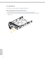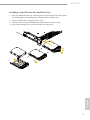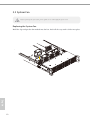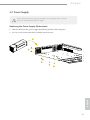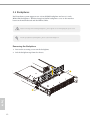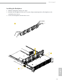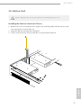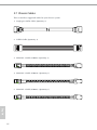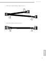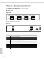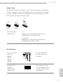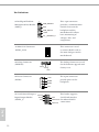
1
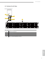
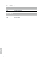
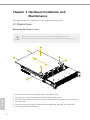
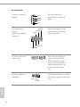
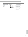
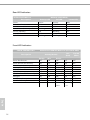
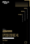
Less Heat, Less Power Consumption
Robust Design, Quality Parts
User Manual
2U12L6SC
Barebone
Stable and
Reliable Solution
STABLE
GREEN
OPEN
Industry Standard, Flexible Architecture
Version 1.0
Published August 2013
Copyright©2013 ASRockRack Inc. All rights reserved.
Copyright Notice:
No part of this documentation may be reproduced, transcribed, transmitted, or
translated in any language, in any form or by any means, except duplication of
documentation by the purchaser for backup purpose, without written consent of
ASRockRack Inc.
Products and corporate names appearing in this documentation may or may not
be registered trademarks or copyrights of their respective companies, and are used
only for identiication or explanation and to the owners’ beneit, without intent to
infringe.
Disclaimer:
Speciications and information contained in this documentation are furnished
for informational use only and subject to change without notice, and should
not be constructed as a commitment by ASRockRack. ASRockRack assumes no
responsibility for any errors or omissions that may appear in this documentation.
With respect to the contents of this documentation, ASRockRack does not provide
warranty of any kind, either expressed or implied, including but not limited to
the implied warranties or conditions of merchantability or itness for a particular
purpose.
In no event shall ASRockRack, its directors, oicers, employees, or agents be liable
for any indirect, special, incidental, or consequential damages (including damages
for loss of proits, loss of business, loss of data, interruption of business and the
like), even if ASRockRack has been advised of the possibility of such damages
arising from any defect or error in the documentation or product.
his device complies with Part 15 of the FCC Rules. Operation is subject to the following
two conditions:
(1) this device may not cause harmful interference, and
(2) this device must accept any interference received, including interference that
may cause undesired operation.
CALIFORNIA, USA ONLY
he Lithium battery adopted on this motherboard contains Perchlorate, a toxic substance
controlled in Perchlorate Best Management Practices (BMP) regulations passed by the
California Legislature. When you discard the Lithium battery in California, USA, please
follow the related regulations in advance.
“Perchlorate Material-special handling may apply, see www.dtsc.ca.gov/hazardouswaste/
perchlorate”
ASRockRack’s Website: www.ASRockRack.com
Important Safety Instructions
Pay close attention to the following safety instructions before performing any of
the operation. Basic safety precautions should be followed to protect yourself from
harm and the product from damage:
• Operation of the product should be carried out by suitably trained, qualiied, and
certiied personnel only to avoid risk of injury from electrical shock or energy hazard.
• Disconnect the power cord from the wall outlet when installing or removing main
system components, such as the motherboard and power supply unit.
• Place the system on a stable and lat surface.
• Use extreme caution when working with high-voltage components.
• When handling parts, use a grounded wrist strap designed to prevent static discharge.
• Keep the area around the system clean and clutter-free.
• Keep all components and printed circuit boards (PCBs) in their antistatic bags when
not in use.
• Handle a board by its edges only; do not touch its components, peripheral chips,
memory modules or contacts.
Contact Information
If you need to contact ASRockRack or want to know more about ASRockRack,
you’re welcome to visit ASRockRack’s website at www.ASRockRack.com; or you
may contact your dealer for further information.
ASRockRack Incorporation
6F., No.37, Sec. 2, Jhongyang S. Rd., Beitou District,
Taipei City 112, Taiwan (R.O.C.)
Contents
Chapter 1 Introduction
1
1.1
Package Contents
1
Chapter 2 Chassis Overview
2
2.1
System Components
2
2.2
System Front View
3
2.3
System Rear View
5
Chapter 3 Hardware Installation and Maintenance
6
3.1
Chassis Cover
6
3.2
Hard Drives
8
3.3
System Fan
10
3.4
Power Supply
11
3.5
Backplanes
12
3.6
Add-on Card
15
3.7
Chassis Cables
16
Chapter 4 Backplane Speciications
18
Appendix A Rails Installation
26
2U12L6SC
Chapter 1 Introduction
hank you for purchasing 2U12L6SC, a reliable barebone system produced
under ASRockRack’s consistently stringent quality control. It delivers excellent
performance with robust design conforming to ASRockRack’s commitment to
quality and endurance.
Because the hardware speciications might be updated, the content of this documentation
will be subject to change without notice. In case any modiications of this documentation
occur, the updated version will be available on ASRockRack’s website without further
notice. If you require technical support related to this product, please visit our website for
speciic information about the model you are using.
ASRockRack’s Website: www.ASRockRack.com
he illustrations shown in this manual are examples only, the actual system may difer
slightly .
1.1 Package Contents
2U12L6SC (2U Form Factor)
Power Supply Unit (pre-installed)
System Fan (pre-installed)
HDD Backplanes x 3 (pre-installed)
Chassis Cables
Screws x 72 (includes 24ea SFF and 48ea LFF)
User Manual
If any items are missing or appear damaged, contact your authorized dealer.
English
•
•
•
•
•
•
•
1
Chapter 2 Chassis Overview
his chapter provides diagrams showing the location of important components of
the server chassis.
2.1 System Components
Cover
Power Supply Units
Air Baffle
M/B
Max. PWM Fan (4 pcs)
Front Controls and Indicators
English
2
12 x 3.5” Hot-Swap HDD Carriers
2U12L6SC
2.2 System Front View
Front Control Panel
1
3
2
4
1
2
3
4
5
Description
System reset button
Power LED
Power Switch
LAN1, LAN2 Activity LED
12 x 3.5" Hot-Swap HDD Carriers
English
No.
5
3
Status LED Deinitions
Power LED
Status
Description
Blue
Of
System is turned on
Power of
LAN1, LAN2 LED
English
4
Status
Description
Green
Of
LAN linked
LAN not linked
2U12L6SC
2.3 System Rear View
1
2
3
4
1
2
3
4
Description
Power supply unit
6 x 2.5" Hot-Swap HDD Carriers
3 x Low Proile PCI Express slots
I/O shield (depends on the speciication of the motherboard)
English
No.
5
Chapter 3 Hardware Installation and
Maintenance
his chapter helps you assemble the chassis and install components.
3.1 Chassis Cover
Removing the Chassis Cover
1. Before removing the top cover, power of the server and unplug the power cord.
2. he system must be operated with the chassis top cover installed to ensure proper cooling.
5
2
3
2
1
4
3
1
English
1. Unscrew the two screws from the sides of the chassis cover.
2. Unscrew the two screws from the back side of the chassis cover.
3. Press the release tabs to remove the cover from the locked position. Press both tabs at
the same time.
4. Once the top cover is released from the locked position, slide the cover outward.
5. Lit the top cover of the chassis.
6
2U12L6SC
Installing the Chassis Cover
2
2
2
1
2
English
1. Slide the chassis cover toward the front of the chassis.
hen latch the cover securely to the chassis.
2. Secure the chassis cover with the screws.
7
3.2 Hard Drives
he 2U12L6SC chassis supports hot-swappable hard drives.
Removing Hard Drive Trays from the Chassis
1. Press the locking lever latch on the drive tray to unlock the retention lever.
2. Rotate the lever out and away from the module bay and pull the hard drive out of the
HDD carrier.
2
1
English
8
2U12L6SC
Installing a Hard Drive to the Hard Drive Tray
1. Place the HDD into the tray with the printed circuit board side facing down.
Carefully align the mounting holes in the hard drive and the tray.
2. Secure the hard drive using the four screws.
3. Slide the drive tray into the HDD bay until the drive is fully seated.
4. Push in the locking lever to lock the HDD tray into place.
3
4
1
English
2
9
3.3 System Fan
Before replacing the system fan, power of the server and unplug the power cord.
Replacing the System Fan
Hold the clip and put the fan module into fan bar. Push all the way until it clicks into place.
English
10
2U12L6SC
3.4 Power Supply
Before replacing the power supply, power of the server, unplug the power cord, and
disconnect all wiring from the power supply.
Replacing the Power Supply (Redundant)
1. Slide the PSU into the power supply module bay until it clicks into place.
2. Use six screws to ix whole PSU assembly on the chassis.
1
2
2
2
English
2
11
3.5 Backplanes
Each barebone system supports one 3.5-inch HDD backplane and two 2.5-inch
HDD/SDD backplanes. he Hot-Swap SAS/SATA backplanes serve as the interface
between the motherboard and the HDDs/SDDs.
Before removing and installing backplanes, power of the server and unplug the power cord.
For the speciication of backplanes, please refer to the Chapter 4.
Removing the Backplane
1. Loosen the securing screws on the backplane.
2. Lit the backplane up from the chassis.
2
1
1
English
12
2U12L6SC
Installing the Backplane
1. Hold the backplane only by the edges.
2. Position the backplane in the server system. Align mounting holes of backplane to the
standof on the chassis.
3. Secure the backplane with the four screw.
1
2
3
English
3
13
he following diagram shows the location of blackplanes on the server chassis.
BP_2x20_S3x4
BP_S2x2_25
BP_S2x1_25
English
14
2U12L6SC
3.6 Add-on Card
Before installing the add-on card, power of the server and unplug the power cord.
Installing the Add-on Card in the Chassis
English
1. Remove the screw securing the cover in place for each low proile add-on slot you want
to use. Keep this screw for later use.
2. Align the add-on card and insert into place.
3. Secure each card to the chassis using the screw previously removed.
15
3.7 Chassis Cables
his section lists supported cables for your chassis system.
1. Single port SATA Cable (Quantity: 2)
2. SGPIO Cable (Quantity: 1)
3. MiniSAS-1 Cable (670mm) (Quantity: 1)
Port 0-3
4. MiniSAS-2 Cable (670mm) (Quantity: 1)
Port 4-7
5. MiniSAS-1 Cable (970mm) (Quantity: 1)
Port 4-7
English
16
2U12L6SC
Rear
P
2x1 B
6. MNG Cable (520mm+100mm)_SMB (Quantity: 1)
Fron
SMB1
t 3x
4 BP
7. MNG Cable (960mm)_SMB (Quantity: 1)
Rear 2
x2
English
BP
SMB3
17
Chapter 4 Backplane Speciications
3.5-inch Hard Drive Backplane ( to connect 12 HDDs)
BP_2x20_S3x4
Front View
CON1
CON2
CON3
CON4
CON5
CON6
CON7
CON8
CON9
CON10
CON11
CON12
12 x SAS/SATA Hot-swap Connectors
Rear View
1
3
2
5
4
PWR2
SMB_1
1
MINI_SAS1
PWR4
UART_SEL
1
SMB_2
1
1
SMB_3
1
MINI_SAS2
DEBUG 1
PWR1
1
BP_2x20_S3x4
PWR3
11
English
18
10
No.
Description
1
2
3
4
5
6
7
8
9
10
11
Power Connector (PWR2)
Power Connector (PWR4)
Mini-SAS Connector (MINI_SAS1)
Mini-SAS Connector (MINI_SAS2)
SMB Connector (SMB_1)
SMB Connector (SMB_3)
SMB Connector (SMB_2)
Debug Connector (DEBUG1)
UART Jumper (UART_SEL1)
Power Connector (PWR1)
Power Connector (PWR3)
9
8
7
6
2U12L6SC
Jumper Setup
he illustration shows how jumpers are setup. When the jumper cap is placed on
the pins, the jumper is “Short”. If no jumper cap is placed on the pins, the jumper
is “Open”. he illustration shows a 3-pin jumper whose pin1 and pin2 are “Short”
when a jumper cap is placed on these 2 pins.
#9 UART Jumper
(UART_SEL1)
1-2:
Conigure the setting of Debug connector for
updating irmware by SDB_TX/RX.
2-3 (Default):
Conigure the setting of Debug connector for
updating debug console by UART.
Pin Deinitions
#3, 4 Mini-SAS
Connector
(MINI_SAS1)
(MINI_SAS2)
he 4-pin connectors
provide power to the
backplane.
+5V
GND1
GND2
+12V
his connector is used
to connect RAID card or
the mini-SAS port on the
motherboard.
English
#1, 2, 10, 11 Power
Connector
(PWR1)
(PWR2)
(PWR3)
(PWR4)
19
#5, 6, 7 SMB Connector
(SMB_1)
(SMB_2)
(SMB_3)
Present#
he SMB (SubMiniature
version B) connector
provides a communication
interface between the
backplane and the
motherboard.
+3V
he Debug Connector is used
for the irmware upgrade and
factory reset.
1
SDA
GND
SCL
+3VSB
TX
#8 Debug Connector
(DEBUG1)
GND
RX
1
English
20
2U12L6SC
2.5-inch Hard Drive Backplane ( to connect 4 HDDs)
BP_S2x2_25
( to connect 4 HDDs)
Front View
CON2
CON4
CON1
CON3
2 x SAS/SATA Hot-swap Connectors
Rear View
1
2 3
1
1
PWR1
DEBUG 1
SGPIO1
MINI_SAS 1
SMB_1
1
BP_S2x2_25
5
4
1
2
3
4
5
Description
Intelligent Platform Management Bus Header (SMB_1)
Mini-SAS Connector (MINI_SAS1)
Debug Connector (DEBUG1)
Power Connector (PWR1)
SGPIO Connector (SGPIO1 )
English
No.
21
Pin Deinitions
#1 Intelligent Platform
Management Bus Header
(SMB_1)
1
IPMB_SMBDATA
GND
IPMB_SMBCLK
+3VSB
I2C_1_PRESENT_N
#2 Mini-SAS Connector
(MINI_SAS1)
his 4-pin connector
provides a communication
interface between the
backplane and the
motherboard. It allows
basic monitoring of
voltages, fans, and
temperature.
his connector is used
to connect RAID card or
the mini-SAS port on the
motherboard.
#3 Debug Connector
(DEBUG1)
he Debug Connector is used
for the irmware upgrade and
factory reset.
1
Debug
#4 Power Connector
(PWR1)
RST#
GND
he 4-pin connectors
provide power to the
backplane.
+12V
GND2
GND1
+5V
#5 Serial General Purpose
Input/Output Header
(SGPIO_1)
SCLOCK
SLOAD
GND
SDATAOUT0
GND
SDATAIN0
1
English
22
his header supports
Serial Link interface
for onboard SATA
connections.
2U12L6SC
BP_S2x1_25 ( to connect 2 SSDs)
Front View
2x SAS/SATA Hot-swap Connectors
CON2
CON1
Rear View
1
2
3
SGPIO1
SAS2
4
1
1
DEBUG 1
BP_S2x1_25
SAS1
PWR1
SMB_1
6
1
2
3
4
5
6
Description
Power Connector (PWR1)
SGPIO Connector (SGPIO1 )
SAS Connector (SAS2)
Debug Connector (DEBUG1)
SAS Connector (SAS1)
Intelligent Platform Management Bus Header (SMB_1)
English
No.
5
23
Pin Deinitions
#1 Power Connector
(PWR1)
+12V
GND2
GND1
he 4-pin connectors
provide power to the backplane.
+5V
#2 Serial General
Purpose
Input/Output Header
(SGPIO_1)
SCLOCK
SLOAD
GND
his header supports Serial
Link interface for onboard
SATA connections.
1
GND
SDATAOUT0
SDATAIN0
#3, 5 SAS Connectors
(SAS1, SAS2)
SAS_2
#4 Debug Connector
(DEBUG1)
1
Debug
English
24
SAS_1
RST#
GND
hese two SAS connectors
support SAS/SATA data
cables for internal storage
devices. he current SAS2/
SATA3 interface allows up
to 6.0 Gb/s data transfer
rate.
he Debug Connector is used for
the irmware upgrade and factory
reset.
2U12L6SC
GND
IPMB_SMBCLK
+3VSB
I2C_1_PRESENT_N
his 4-pin connector
provides a communication
interface between the
backplane and the
motherboard. It allows
basic monitoring of
voltages, fans, and
temperature.
English
IPMB_SMBDATA
1
#6 Intelligent Platform
Management Bus
Header
(SMB_1)
25
Rear LED Indicators
SGPIO-SDATAOUT bit
Description
Status
Drive Not Present
Drive Present, No Activity
Drive Present, Activity
Locate (Identify)
Drive Fail
Rebuild
MG9081 (SATA HDD)
Activity LED
Green
Of
On
Blinking
Of
Of
Blinking
Fail LED
Orange
Of
Of
Of
Blinking
Of
Blinking
Locate LED
Blue
Of
On
On
On
Of
On
Front LED Indicators
SGPIO-SDATAOUT bit
ASRock Rack BPB LED Behavior (SAS/SATA HDD)
Description
Drive Not Present
Drive Present, No Activity
Drive Present, Activity
Locate (Identify)
Drive Fail
Rebuild
PFA (Predicted Failure Analysis)
Hotspare
In A Critical Array
In A Failed Array
English
26
Activity(Green)
Empty
Idle
Access
Of
Of
Of
Of
Of
Of
Of
Of
Of
Of
Of
On
Of
Of
Of
Of
On
Of
On
On
Of
Of
Blinking
Of
Of
Blinking
Of
Of
Of
Of
Blink Freq
0.25 s
Fail
(Red)
Of
Of
Of
Blink
Of
Blinking
Blinking
Of
Blinking
Blinking
Blink Freq
0.5 s
Locate
(Blue)
Of
On
On
On
Of
On
Of
Of
Of
Of
2U12L6SC
Appendix A Rails Installation
he rails installation instructions in this manual are example only, your actual rail
assembly procedure may difer slightly .
Installing the Rails
1. Pull out the inner rail from rail assembly by pulling the front activating release latch
forward.
3
English
2. Secure the inner rails directly to the sides of the chassis using screws.
27
3. Each slide is pre-attached with front and rear adjustable EIA brackets.
Loosen the nuts on the both brackets, and decide the proper setback distance to the
opening, then tighten the nuts on the front brackets.
4. Extend the rear brackets to where it reaches the rear rack. Do not fully tighten rear
bracket mounting screws until inal adjustment is made.
Repeat Step 3&4 above for other side of outer slide member.
5. Attach the L-shaped bracket to the front mounting lange using screws and nylon ring.
Repeat Step 5 for the other side of slide.
English
28
2U12L6SC
Optional Slide Rail Kit
he optional slide rail kit is available for you to order, as listed below.
Vendor
Model name
Chenbro
84H341300-002
English
Optional Accessory – Slide Rail Kit
29