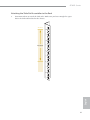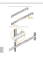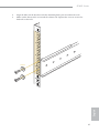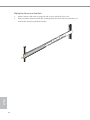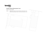
1
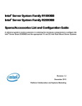
4U60L Series
User Manual
Version 1.0
Published June 2015
Copyright©2015 ASRock Rack INC. All rights reserved.
Version 1.0
Published June 2015
Copyright©2015 All rights reserved.
Copyright Notice:
No part of this documentation may be reproduced, transcribed, transmitted, or translated
in any language, in any form or by any means, except duplication of documentation by the
purchaser for backup purpose, without written consent of us.
Products and corporate names appearing in this documentation may or may not be
registered trademarks or copyrights of their respective companies, and are used only for
identiication or explanation and to the owners’ beneit, without intent to infringe.
Disclaimer:
Specifications and information contained in this documentation are furnished for
informationa l use only and subject to change without notice, and should not be
constructed as a commitment by us. We assumes no responsibility for any errors or
omissions that may appear in this documentation.
With respect to the contents of this documentation, we do not provide warranty of any
kind, either expressed or implied, including but not limited to the implied warranties or
conditions of merchantability or itness for a particular purpose.
In no event shall we, our directors, oicers, employees, or agents be liable for any indirect,
special, incidental, or consequential damages (including damages for loss of proits, loss of
business, loss of data, interruption of business and the like), even if we have been advised
of the possibility of such damages arising from any defect or error in the documentation or
product.
his device complies with Part 15 of the FCC Rules. Operation is subject to the following
two conditions:
(1) this device may not cause harmful interference, and
(2) this device must accept any interference received, including interference that
may cause undesired operation.
CALIFORNIA, USA ONLY
he Lithium battery adopted on this motherboard contains Perchlorate, a toxic substance
controlled in Perchlorate Best Management Practices (BMP) regulations passed by the
California Legislature. When you discard the Lithium battery in California, USA, please
follow the related regulations in advance.
“Perchlorate Material-special handling may apply, see www.dtsc.ca.gov/hazardouswaste/
perchlorate”
Important Safety Instructions
Pay close attention to the following safety instructions before performing any of
the operation. Basic safety precautions should be followed to protect yourself from
harm and the product from damage:
• Operation of the product should be carried out by suitably trained, qualiied, and
certiied personnel only to avoid risk of injury from electrical shock or energy hazard.
• Disconnect the power cord from the wall outlet when installing or removing main
system components, such as the motherboard and power supply unit.
• Place the system on a stable and lat surface.
• Use extreme caution when working with high-voltage components.
• When handling parts, use a grounded wrist strap designed to prevent static discharge.
• Keep the area around the system clean and clutter-free.
• Keep all components and printed circuit boards (PCBs) in their antistatic bags when
not in use.
• Handle a board by its edges only; do not touch its components, peripheral chips,
memory modules or contacts.
Contents
Chapter 1 Introduction
1
1.1
System Package Contents
2
1.2
Speciications
3
Chapter 2 Server System Overview
4
2.1
System Components
5
2.2
Board Arrangement
7
2.3
System Front Panel
8
2.4
System Rear Panel
9
2.5
Front Control Panel Buttons and LEDs
10
2.6
Drive Tray LEDs
12
2.7
PSU LED
13
2.8
Fan Failed LED (Middle System Fan)
13
2.9
Backplane LEDs
14
Chapter 3 Hardware Installation and Maintenance
15
3.1
Server Top Cover
16
3.2
Hard Drive
18
3.2.1 Installing a Hard Disk Drive into 2.5" Hard Drive Tray
18
3.2.2 Installing a 3.5” or 2.5” Hard Disk Drive into the Hard
Drive Carrier
20
3.3
Power Supply
24
3.4
Add-on Card
26
3.5
System Fan
28
3.6
Motherboard
30
3.7
Daughter Board
32
Appendix A
35
Installing the CPU (Socket: LGA2011)
35
Installing the CPU Fan and Heatsink
38
Installation of Memory Modules (DIMM)
39
Appendix B
40
Installing the Server in a Rack
40
4U60L Series
Chapter 1 Introduction
hank you for purchasing ASRock Rack 4U60L Series, a reliable barebone system
produced under ASRockRack’s consistently stringent quality control. It delivers excellent
performance with robust design conforming to ASRockRack’s commitment to quality and
endurance.
Because the hardware speciications might be updated, the content of this documentation
will be subject to change without notice. In case any modiications of this documentation
occur, the updated version will be available on ASRockRack’s website without further
notice. If you require technical support related to this product, please visit our website for
speciic information about the model you are using.
ASRockRack’s Website: www.ASRockRack.com
English
he illustrations shown in this manual are examples only, the actual system may difer
slightly .
1
1.1 System Package Contents
he system can be conigured to operate in three diferent modes: HA (High Availability),
Zoning, and Single Node (JBOD).* Please refer to the table below for the required
components for each mode.
Quantity for Diferent Mode
Item
4U60L Series Barebone (4U form factor)
HA
Zoning
Single Node
1
1
1
Motherboards (MB)**
2
2
1
Expander Board (EXPB)
2
1
1
Expander Board (EXPBZ)
0
1
0
HA Daughter Board (DBH)***
1
0
0
Zoning Daughter Board (DBZ)***
0
1
0
Single Node Daughter Board (DBJ)***
0
0
1
Right Power Distribution Board (RPDB)
1
1
0
Let Power Distribution Board (LPDB)
1
1
1
Middle Plane Board (MPB)
1
1
1
3.5"/2.5" HDD Back Plane Board (BPB)
5
5
5
2.5" HDD Back Plane Board (BPB)
2
2
1
Front Panel Board (FPB)
2
2
1
Power Supply Units
4
4
4
System Fans
9
9
9
Accessory Box
1
1
1
Support CD
1
1
1
User Manual
1
1
1
* For more details about motherboard conigurations, please refer to the section entitled “3.6 Motherboard“.
** he system supports E3C224D4HM-8R motherboard. Please go the oicial website for the latest supported
list and information.
*** Only one of the daughter boards is pre-installed. You can ind the other two in the accessory box.
If any items are missing or appear damaged, contact your authorized dealer.
English
2
4U60L Series
1.2 Speciications
4U60L Series
System Physical Status
Form Factor
4U Rackmount
Dimension
35.4"* x 16.9" x 6.94" (900* x 430 x 176.5 mm)
*Chassis ears excluded
(D x W x H)
Support MB Size Half Width, 13'' x 5.96'' (330 x 151 mm)
Front Panel (1 for each motherboard)
Buttons
LEDs
• 2 x Power On/Of buttons
• 2 x ID buttons
• 2 x System reset buttons
• 2 x NMI buttons
• 2 x Power LEDs
• 2 x ID LEDs
• 2 x HDD activity LEDs
• 8 x LAN activity LEDs
• 2 x System Event LEDs*
*System Event LED is not supported for E3C224D4HM-8R motherboard.
I/O Ports
Drive Bay
External
System Cooling
Fan (Front)
Fan (Middle)
Power Supply
Capacity
Output Watts
Eiciency
4 x USB 2.0 ports
• 60 x 3.5'' Bay HDD (12Gb/s)
• 4 x 2.5'' Bay HDD (2 for each motherboard)
5 x 80*38 mm system fans
4 x 92*38 mm system fans
4 (3+1) Redundant
800W
Platinum
English
Please refer to the user manual of the motherboard you use for detailed information about
motherboard components and features.
3
Chapter 2 Server System Overview
his chapter provides diagrams showing the location of important components of
the server system.
4U60L Series:
English
4
4U60L Series
2.1 System Components
1
2
5
4
31
HDD3
HDD59
HDD2
HDD58
6
HDD1
HDD57
13
10
12
14
English
11
9
HDD0
8
HDD4
HDD8
HDD12
HDD56
7
5
No.
English
6
Item
1
Front System Fan (Fan5)
2
Front System Fan (Fan4)
3
Front System Fan (Fan3)
4
Front System Fan (Fan2)
5
Front System Fan (Fan1)
6
60 x 3.5'' or 2.5" HDD Bays (HDD0~HDD59)
7
Middle System Fan (Fan9)
8
Middle System Fan (Fan8)
9
Middle System Fan (Fan7)
10
Middle System Fan (Fan6)
11
Node2
12
Node1
13
2 x 2.5” Hot-Swap HDD Trays (for Node 2)
14
2 x 2.5” Hot-Swap HDD Trays (for Node 1)
4U60L Series
2.2 Board Arrangement
1
2
3
4
5
6
8
10
12
14
7
9
11
13
15
No.
Item
1
3.5"/2.5" HDD Backplane Board 5 (BPB5)
2
3.5"/2.5" HDD Backplane Board 4 (BPB4)
3
3.5"/2.5" HDD Backplane Board 3 (BPB3)
4
3.5"/2.5" HDD Backplane Board 2 (BPB2)
5
3.5"/2.5" HDD Backplane Board 1 (BPB1)
6
Daughter Board (DB)*
7
Middle Plane Board (MPB)
Expander Board 2 (EXPB2)
*Not required for the Single Node Mode
**Use the EXPBZ Expander Board instead for the Zoning Mode
9
Expander Board 1 (EXPB1)
10
Let Power Distribution Board (LPDB)
11
Right Power Distribution Board (RPDB)
12
Motherboard 2 (MB2)
*Not required for Single Node Mode
13
Motherboard 1 (MB1)
14
2.5" HDD Backplane Board for Node 2 (BPB7)
15
2.5" HDD Backplane Board for Node 1 (BPB6)
*You can change the Daughter Board (DBH/DBZ/DBJ) to support diferent modes and toggle among HA, Zoning
or Single Node. Node 2 doesn't support Single Node function. For more information, please refer to 3.6 Motherboard Conigurations.
English
8
7
2.3 System Front Panel
1
No.
English
8
2
3
Item
1
Control Panel Buttons and LEDs (Let) (for Node 1)
2
2 x USB 2.0 Ports (Let) (for Node 1)
3
5 x HDD Backplane Trays
4
2 x USB 2.0 Ports (Right) (for Node 2)
5
Control Panel Buttons and LEDs (Right) (for Node 2)
4
5
4U60L Series
2.4 System Rear Panel
WARNING! Do NOT open the trays if the server
is not powered down or while it is still running.
!
1
No.
2
3
4
5
6
7
8
9 10 11 12
Item
Add-on Card Slot (MB2)
1
*Supports Low proile and FHHL (Full High Half Length) add-on cards
**When the PCIE1 slot on the E3C224D4HM-8R motherboard is populated, the LSI SAS connectors will be disabled.
2
I/O Shield (depends on the speciication of the motherboard) (MB2)
3
2.5" HDD trays (MB2)*
4
*WARNING! Please do NOT open the tray if the server is not powered down or while it is still
running.
5
Mezzanine Card Support for 1GbE x 2, 10GbE x2 or SFP+ (Fiber) x2 (MB2)
6
Rear Vent
Motherboard Node Tray Handle (Node2)|
Add-on Card Slot (MB1)
7
*Supports Low proile and FHHL (Full High Half Length) add-on cards
**When the PCIE1 slot on the E3C224D4HM-8R motherboard is populated, the LSI SAS connectors will be disabled.
8
I/O Shield (depends on the speciication of the motherboard) (MB1)
9
2.5" HDD trays (MB1)*
10
*WARNING! Please do NOT open the tray if the server is not powered down or while it is still
running.
11
Mezzanine Card Support for 1GbE x 2, 10GbE x2 or SFP+ (Fiber) x2 (MB1)
12
4 x Power Supply Units
English
Motherboard Node Tray Handle (Node1)
*To conigure an appliance for High Availability (HA) mode , the 2.5" HDD trays are dedicated for OS installation per node.
9
2.5 Front Control Panel Buttons and LEDs
Front Control Panel Boards
PWR
BTN
1
PWR
BTN
8
UID
2
UID
9
L1
L2
L3
L4
3
L1
L2
L3
L4
!
4
6
!
5
7
NMI
No.
10
11
13
RST
12
14
NMI
RST
Item
1
MB1 Power Button and LED
2
MB1 ID Button and LED*
3
MB1 LAN1, LAN2, LAN3, LAN4 Activity LEDs*
4
MB1 HDD Activity LED
5
MB1 System Event LED*
6
MB1 NMI (Nonmaskable Interrupt) Button*
7
MB1 System Reset Button
8
MB2 Power Button and LED
9
MB2 ID Button and LED*
10
MB2 LAN1, LAN2, LAN3, LAN4 Activity LEDs*
11
MB2 HDD Activity LED
12
MB2 System Event LED*
13
MB2 NMI (Nonmaskable Interrupt) Button*
14
MB2 System Reset Button
*Please be noted that the functions are supported depending on the type of the motherboard.
English
Power Button
Press the power switch button to toggle the system power on and of.
To remove all power from the system completely, disconnect the power cord from the
server.
10
4U60L Series
ID Button
Press the ID button to toggle the front panel ID LED and the baseboard ID LED on and
of. You are able to locate the server you’re working on from behind a rack of servers.
NMI (Nonmaskable Interrupt) Button
Press the NMI button with a paper clip or pin to generate a nonmaskable interrupt and to
put the server in a halt state for examination.
System Reset Button
When the system is completely unresponsive, press the system reset button to reboot the
server without shutting it of and initialize the system.
Status LED Deinitions
Power LED
Status
Description
Green
Of
Power on
Power of
ID LED
Status
Description
Blue
Of
System identiication is active.
System identiication is disabled.
LAN1, LAN2, LAN3, LAN4 LEDs
Status
Description
Green
Blinking Green
Link between system and network or no access
Network access
HDD Activity LED
Status
Description
Blinking Green
Of
HDD access
HDD idle
Status
Description
Of
Red
Running or normal operation
At least one sensor has critical alert
English
System Event LED*
*System Event LED is not supported for E3C224D4HM-8R motherboard.
11
2.6 Drive Tray LEDs
1
2
No.
Description
1
2
HDD Power LED
HDD Activity LED
Status LED Deinitions
HDD Power LED
Status
Description
Blue
Of
HDD powered-on
No power to HDD
HDD Activity LED
English
12
Status
Description
Solid Green
Blinking Green
Red
Of
HDD active
HDD accessing or reading
HDD failed
HDD powered-of
4U60L Series
2.7 PSU LED
PSU LED
PSU Status LED
Status
Description
Green blinking at 1Hz
Green
Amber continuously
Amber blinking at 1Hz
Green blinking at 0.5Hz
Standby/Cold redundant state or PDB fault/protection
Normal work
Module fault/protection in operating mode
Warning
Power cord unplugged/AC loss
2.8 Fan Failed LED (Middle System Fan)
Fan Failed LED
Fan LED
Status
Description
Solid Amber
Of
Fan failed
Normal
English
* To know the status of the front system fans, please check the Fan LED indicators on the corresponding
backplane boards.
13
2.9 Backplane LEDs
BPB1
1
2
3
BPB2
4
5
6
7
BPB3
8
9
10
11
BPB4
12
13
14
15
BPB5
16
17
18
20
No.
LED
Status
Description
1
2
3
4
5
6
7
8
9
10
11
12
13
14
15
16
17
18
19
20
BPB1 HDD Activity
BPB1 HDD Error
BPB1 PWR Error
BPB1 FAN Error
BPB2 HDD Activity
BPB2 HDD Error
BPB2 PWR Error
BPB2 FAN Error
BPB3 HDD Link
BPB3 HDD Error
BPB3 PWR Error
BPB3 FAN Error
BPB4 HDD Link
BPB4 HDD Error
BPB4 PWR Error
BPB4 FAN Error
BPB5 HDD Link
BPB5 HDD Error
BPB5 PWR Error
BPB5 FAN Error
Blinking Green
Solid Red
Solid Amber
Solid Amber
Blinking Green
Solid Red
Solid Amber
Solid Amber
Blinking Green
Solid Red
Solid Amber
Solid Amber
Blinking Green
Solid Red
Solid Amber
Solid Amber
Blinking Green
Solid Red
Solid Amber
Solid Amber
HDD0~HDD11 active and accessing*
BPB1 HDD error
BPB1 power error
BPB1 Fan1 error
HDD12~HDD23 active and accessing*
BPB2 HDD error
BPB2 power error
BPB2 Fan2 error
HDD24~HDD35 active and accessing*
BPB3 HDD error
BPB3 power error
BPB3 Fan3 error
HDD36~HDD47 active and accessing*
BPB4 HDD error
BPB4 power error
BPB4 Fan4 error
HDD48~HDD59 active and accessing*
BPB5 HDD error
BPB5 power error
BPB5 Fan5 error
*Please refer to the 2.1 System Components (p.5) for the locations and numbering of the hard drives.
English
14
19
4U60L Series
Chapter 3 Hardware Installation and
Maintenance
his chapter helps you assemble the chassis and install components.
Before You Begin
Before you work with the server, pay close attention to the “Important Safety Instructions”
at the beginning of this manual.
1. Make sure the server is powered of.
Power down the server if it is still running.
(1) Press the Power button to power of the server from full-power mode to power-of
mode. he Power LED at the front turns from solid green to of.
(2) Disconnect the power cord irst from the AC outlet and then from the server.
he power LED turns of.
he server is not completely powered down when you press the Power button on the front
panel. Some internal circuitry remain active in the Power-of mode. To remove all power
from the system completely, be sure to disconnect the power cord from the server.
2. Ensure you have a clean and stable working environment. Avoid dust and dirt because
contaminants may cause malfunctions.
3. Ground yourself properly before touching any system component. A discharge of static
electricity may damage components. Wear a grounded wrist strap if available.
English
Ater all components are well installed, then you can connect the power cord to the AC
outlet and then press the Power button to power on the server.
15
3.1 Server Top Cover
Removing the Server Top Cover
1. Before removing the top covers, power of the server and unplug the power cord.
2. he system must be operated with all the chassis top covers installed to ensure proper cooling.
1. Remove the eight screws that secure the top cover to the chassis.
2. Push the top cover toward the FRONT of the chassis to remove the cover from the
locked position.
3. Lit up and remove the top cover.
1
3
2
1
English
16
4U60L Series
Installing the Server Top Cover
1. Lower the top cover on the chassis, making sure the side latches align with the cutouts.
2. Slide the top front cover toward the REAR of the chassis.
3. Secure the top cover with the eight screws.
3
1
2
English
3
17
3.2 Hard Drive
3.2.1 Installing a Hard Disk Drive into 2.5" Hard Drive Tray
he 4U60L series chassis supports hot-swappable 2.5" hard drives. Four 2.5" hard
drive trays are located on the rear of the chassis.
Removing 2.5” Hard Drive Trays from the Chassis
1. Press the locking lever latch on the drive tray to unlock the retention lever.
2. Rotate the lever out and away from the module bay and pull the hard drive out of the
HDD tray.
2
1
English
18
4U60L Series
Installing a 2.5” Hard Drive to the Hard Drive Tray
1. Place a 2.5" HDD into the tray with the printed circuit board side facing down.
Carefully align the mounting holes in the hard drive and the tray.
2. Secure the hard drive using the two screws.
3. Slide the drive tray into the HDD bay until the drive is fully seated.
4. Push in the locking lever to lock the HDD tray into place.
2
3
4
English
1
19
3.2.2 Installing a 3.5” or 2.5” Hard Disk Drive into the Hard Drive Carrier
Removing a Hard Drive Carrier from the Chassis
1. Push back the black release latch.
2. While holding the latch back in the unlocked position, pull the hard drive carrier up
and out towards you. Release the latch ater the carrier has been removed.
2
1
English
20
4U60L Series
Installing a 3.5” Hard Drive to the Hard Drive Carrier
1. Remove the screws to disengage the hard drive mounting bracket from the carrier.
2. Place the 3.5" HDD into the bracket with the label facing up and the connector end
toward the opening of the bracket.
Carefully align the mounting holes in the hard drive and the carrier.
3. Use the four screws to secure the hard drive into the bracket.
1
Hard Drive Mounting Bracket
3
English
2
21
Installing a 2.5” Hard Drive to the Hard Drive Carrier
1. Place the 2.5" HDD into the carrier with the label facing up and the connector end toward
the rear of the carrier.
Carefully align the mounting holes in the hard drive and the carrier.
2. Secure the hard drive using the four screws.
3. Place the hard drive carrier back to into the chassis.
1
English
22
2
4U60L Series
Installing a Hard Drive Carrier into the Chassis
1. Gently slide the HDD carrier into the chassis evenly.
2. Push the carrier downwards until it is irmly seated and locks into place.
1
2
English
2
23
3.3 Power Supply
The 4U60L Series can accommodate four CRPS (Common Redundant Power Supplies)
power supplies in the bay at the rear of the chassis. Each unit provides up to 800 Watts
of power. hree power supplies are required for operation, with the other power supply
purely as a redundant, load-sharing backup. It can be removed without afecting system
operation.
Before replacing the power supply, power of the server, unplug the power cord, and disconnect all wiring from the power supply.
Installing and Removing the Power Supply
Installing the Power Supply Unit
1. Align the power supply unit with the power supply slot. Ensure that the LED appears
on the lower right when you are installing the power supply unit.
2. Carefully slide the PSU all the way into the power supply bay until it clicks into place.
1
2
English
24
4U60L Series
Removing the Power Supply Unit
To remove a failed power supply, identify the failed power supply by checking the
power supply LEDs on the PSU.
1. Hold onto the power supply handle while pressing the locking lever towards the power
supply handle.
2. Pull to remove the power supply from the chassis.
2
1
1
English
1. Before replacing the power supply, power of the server, unplug the power cord, and
disconnect all wiring from the power supply.
2. In a redundant system, you do not need to power down the server.
25
3.4 Add-on Card
Before installing the add-on card, power of the server and unplug the power cord.
Installing the Add-on Card in the Chassis
1. Remove the screw securing the cover in place for each low proile add-on slot you want
to use. Keep this screw for later use.
2. Align the add-on card and insert into place.
3. Secure each card to the chassis using the screw previously removed.
English
1. You can install an add-on card to the chassis only when you have a riser card installed on the
motherboard.
2. Before installing the add-on card, power of the server and unplug the power cord.
26
4U60L Series
Removing the Blanking Plate for a LAN Mezzanine Card
You can use an optional Ethernet mezzanine card for additional LAN ports. Please be
aware that the mezzanine card must be used in conjunction with a matching I/O module.\
English
Remove the two screws that secure the blanking plate on the chassis. Keep this
screw for later use.
27
3.5 System Fan
he 4U60L series chassis supports hot-swappable system fans.
Replacing the System Fan
Before replaceing the system fan, remove the top cover from the chassis. (See p. 16 for more
details.)
Front Fan Module
1. Push back the release latch at the top of the front fan.
2. While holding the latch back in the unlocked position, pull the fan up and out towards
you. Release the latch ater the fan has been removed.
1
2
English
28
4U60L Series
Middle Fan Module
1. Press and hold the clip on the middle fan
2. Lit the system fan away from the chassis.
1
English
2
29
3.6 Motherboard
Attention! DO NOT open the motherboard tray if the server is not powered down or while
it is still running.
Replacing the Motherboard
You must remove all connected cables from the motherboard to avoid damaging the
motherboard and its components when you remove it later.
1.
2.
3.
4.
5.
Release the thumb screw on the tray if it is tightened.
Pull the motherboard node tray handle downward.
Slide back the motherboard node tray.
Carefully slide the tray completely out of the chassis.
Remove the screws that secure the motherboard to the node tray. Lit to remove the
motherboard.
6. Reverse the procedure to install a motherboard.
1
3
2
5
English
4
30
4U60L Series
Motherboard Conigurations
Board
HA Mode
Zoning Mode
Single Node Mode
DB
DBH
DBZ
DBJ
EXPB1
EXPB
EXPB
EXPB
EXPB2
EXPB
EXPBZ
N/A
MB
MB1
HDD
MB2
MB1
MB2
MB1
MB2
V
V
V
N/A
30
30
60
N/A
V
V
60
idle
idle
60
HA(High Availability) Mode:
Node1 and Node2 support 60 SAS HDDs. When one of the nodes operates
normally, the other node idles. If an unexpected error, crash or shutdown occurs on
the operating node, the idle node then takes over the job.
To support HA, you need to install both motherboard 1 in Node1 and motherboard
2 in Node 2 and change your daughter board to DBH.
Zoning Mode:
Each node runs the job individaully. Each node supports 30 SAS or SATA HDDs.
To support Zoning, you need to install both motherboard 1 in Node1 and
motherboard 2 in Node 2 and change your daughter board to DBZ.
Single Node Mode:
Only Node1 supports 60 SAS or SATA HDDs. Node2 is not functioning.
To support Single Node, you only need to install motherboard 1 in Node1 and
change your daughter board to DBJ.
English
To know more about how to change a daughter board, refer to the section entitled
"3.7 Daughter Board".
Refer to the user manual of the motherboard you use for instructions on how to install
motherboard components.
31
3.7 Daughter Board
Replacing the Daughter Board
Depending on the HA mode, Zoning mode or Single Node mode you require for
your system, install the compatible daughter board for proper functionality.
HA Mode
Zoning Mode
Single Node Mode
DBH
DBZ
DBJ
CON1
CON3
CON1
CON3
CON1
4U60L_DBH
CON3
4U60L_DBZ
4U60L_DBJ
CON2
CON4
CON2
CON4
Before replacing a daughter board, you must power down the system completely.
1. Remove the top cover. For more details, please refer to the section entitled "3.1 Server
Top Cover".
2. Remove the screws that secure the daughter board bracket to the chassis. Remove the
daughter board bracket and set it aside for re-assembly.
English
32
4U60L Series
3. Gently and vertically lit up and remove the daughter board from the Expander Board
(EXPB).
ZONING MOD
E
4. Correctly orientate the daughter board you need. When facing the rear of the chassis,
the CON1 on the daughter board you are about to install should be at the right-bottom
corner.
DB
CON1
Node1
(MB1)
English
Node2
(MB2)
1. he daughter board must be lit up or installed vertically. Installing the daughter board
incorrrectly may cuase irreparable damage to the connector pins.
2. When you change the daughter board to switch among diferent system modes, do not forget to
change the relavant cable connections as you need.
33
5. Align the connectors on the daughter board with the Expander Board card connectors.
Vertically install the daughter board to the the Expander Board card with a little
pressure.
6. hen install the daughter board bracket back to the chassis with screws.
English
7. Replace the top cover.
34
4U60L Series
Appendix A
Installing the CPU
1. Before you insert the 1150-Pin CPU into the socket, please check if the PnP cap is on the socket,
if the CPU surface is unclean, or if there are any bent pins in the socket. Do not force to insert
the CPU into the socket if above situation is found. Otherwise, the CPU will be seriously damaged.
2. Unplug all power cables before installing the CPU.
1
A
B
3
English
2
35
4
5
6
English
Please save and replace the cover if the processor is removed. he cover must be placed if
you wish to return the motherboard for ater service.
36
4U60L Series
Installing the CPU Fan and Heatsink
Before you installed the heatsink, you need to spray thermal interface material between the
CPU and the heatsink to improve heat dissipation.
2
English
1
37
Installation of Memory Modules (DIMM)
he DIMM only its in one correct orientation. It will cause permanent damage to the
motherboard and the DIMM if you force the DIMM into the slot at incorrect orientation.
For more information about DIMM installation, please refer to the User Manual that
comes with the serverboard you use.
1
2
3
English
38
4U60L Series
Appendix B
Installing the Server in a Rack
his section describes how to rackmount the server with slide rail assemblies.
1. he rails installation instructions in this manual are example only, your actual rail
assembly procedure may difer slightly .
2. Please purchase the rail assembly seperately if needed.
he slide rail assembly consists of a chassis rail and a slide rail.
You need to attach the chassis rails to the server and attach the slide rail assemblies to the
rack.
Slide Rail
3
Chassis Rail
Removing the Chassis Rail from the Slide Rail Assembly
3.
Pull out the inner chassis rail from the rail assembly.
Push the white chassis rail release button toward the front, and simultaneously
withdraw the chassis rail from the slide rail assembly.
Repeat for the remaining rail assembly.
2
English
1.
2.
1
39
To slide a chassis rail back into the slide rail assembly, slide the blue release tab toward the
rear, and simultaneously slide the chassis rail into the slide rail assembly until it is locked
and cannot be pushed further.
Attaching the Chassis Rails to the Server
1.
2.
3.
English
40
Position a chassis rail along one side of the chassis, and align the keyhole openings on
the chassis rail with the keyhole openings on the side of the chassis.
Secure the chassis rail to the server chassis with screws.
Repeat for the remaining chassis rail.
4U60L Series
Attaching the Slide Rail Assemblies to the Rack
Determine where to attach the slide rails. Make sure you have enough free space
above the slide rail bracket for the chassis.
4U Server
12
U
Free Space
11U
1
10
U
9U
8U
English
1.
41
2.
Extend the pre-attached front and rear adjustable brackets on the slide.
Rear Bracket
Front Bracket
3.
Adjust the brackets to accommodate the depth of the rack.
11U
English
42
4U60L Series
Align the holes on the brackets with the mounting holes you selected on the rack.
Add a washer between the screw and the cabinet rail. Tighten the screw to secure the
slide rails to the rack.
12
U
11U
10
U
Washer
9U
8U
English
4.
5.
43
Sliding the Server into the Rack
1.
2.
English
44
Ensure that the slide rails are properly and securely attached to the rack.
Fully extend the slide rails from the rack by pulling the inner rails out until they are
locked and cannot be pulled out further.
4U60L Series
Slide the release tabs on both sides and slide the server slowly and evenly all the way
into the cabinet to ensure that the slide assemblies are working correctly.
he server is heavy. For safe liting, two or more persons are required to install the server
into the rack.
Release Tab
English
3.
45
4.
5.
Tighten the two thumb screws on the front of the server to secure the server to the
rack.
To remove the server from the rack, reverse these instructions.
When connecting cables to the server, make sure there is enough cable slack so you can slide
the server in and out of the rack without accidentally unplugging a cable.
Optional Accessory
Please purchase the following optional accessory seperately if needed.
Rail Assembly Kit
English
46
Vendor
Model Name
KINGSLIDE
AR60-940