1
TA502
Installation Instructions
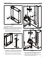
NOTE: Ensure screws are far enough from block end to
prevent interference with framing screws installed in InWall Enclosure Installation section.
3.
If necessary, cut rectangular hole in horizontal framing to
accommodate the PAC-GB1 Listed electrical box accessory
(not included).
4.
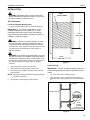
Attach horizontal framing to each support block with two
#10 x 2-1/2" countersunk wood screws (not provided).
(See Figure 2)
7
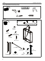
(D) x 4
In-Wall Enclosure Installation
1.
Install PAC-GB1 Listed electrical box accessory (not
included) into the TA502 (A) following instructions included
with the PAC-GB1.
2.
Connect electrical wiring.
3.
Route audio/visual cables into housing.
4.
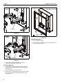
Center TA502 (A) in opening and insert into opening.
5.
Align front of box with front face of wall. (See Figure 3)
(B) x 4
Figure 4
(A)
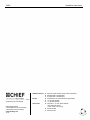
8.
Drill four 3/16" diameter pilot holes in horizontal framing at
mounting holes.
9.
Attach the TA502 (A) to horizontal framing using four M7 x
40mm Allen head connector screws (C) using an M4 Allen
head drill bit (F). (See Figure 5)
Side Mounting
Holes
9
(C) x 4
Figure 3
WARNING: ELECTRICAL SHOCK HAZARD! CUTTING
OR DRILLING INTO ELECTRICAL WIRES OR
CABLES CAN CAUSE DEATH OR SERIOUS
PERSONAL INJURY! ALWAYS make certain area behind
mounting surfaces is free of electrical wires and cables
before cutting, drilling, or installing fasteners.
6.
Drill four 3/16" diameter pilot holes in studs at side mounting
holes. (See Figure 3)
7.
Attach the TA502 (A) using four M7 x 50mm Allen head
connector screws (D) and four spacers (B) into pilot holes
using an M4 Allen head drill bit (F). (See Figure 4)
NOTE: The TA502 has 1/2" total clearance between the two
studs. The spacers allow side to side adjustment.
6
Figure 5
DANGER: IMPROPER WIRING CAN LEAD TO DEATH
OR SEVERE PERSONAL INJURY! Grounding must be
installed by qualified personnel using a UL Recognized No.
12AWG grounding wire connected to grounding lug on
mount.