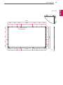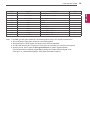
1
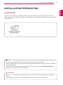
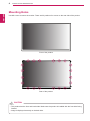
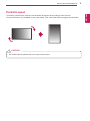
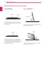
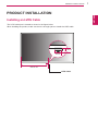
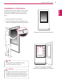
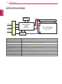
ENG
ENGLISH
OWNER’S MANUAL
MONITOR SIGNAGE
Please read this manual carefully before operating the your set and
retain it for future reference.
MONITOR SIGNAGE MODELS
47TS50MF
www.lg.com
2
CONTENTS
ENGLISH
ENG
CONTENTS
3
INSTALLATION PREPARATION
3
Accessories
4
Mounting Holes
5
Portrait Layout
6
Storage Method for Panel Protection
6
- Correct Method
6
- Incorrect Method
7
PRODUCT INSTALLATION
7
Installing an LVDS Cable
8
Lighting Installation
9
Installation in Enclosure
10
Precaution
10
- Correct Method
10
- Incorrect Method
11
TROUBLESHOOTING
12 SPECIFICATIONS
14 LVDS PIN MAP GUIDE
NOTE
The warranty will not cover any damages caused by using the product in an excessively dusty
yy
environment.
INSTALLATION PREPARATION
3
Accessories
Check your product box for the following items. If there are any missing accessories, contact the local
dealer where you purchased your product. The illustrations in this manual may differ from the actual product
and accessories.
CD (Owner's Manual)/
Easy Setup Guide
NOTE
The accessories supplied with your product may vary depending on the model.
yy
Product specifications or contents in this manual may be changed without prior notice due to upgrade
yy
of product functions.
LVDS cable is optional and not provided with the product. Please refer to LVDS Pin Map Guide on
yy
pages 14 to 15 for the LVDS cable assembly.
CAUTION
Do not use any unapproved or counterfeit parts or accessories to ensure the safety and product life
yy
span.
Any damages or injuries by using unapproved items are not covered by the warranty.
yy
ENG
ENGLISH
INSTALLATION PREPARATION
4
INSTALLATION PREPARATION
Mounting Holes
ENGLISH
ENG
Use M3 screws to mount the monitor. There are 20 positions for screws on the rear side of the product.
Front of the product
Rear of the product
CAUTION
This product has the front and back sides. Make sure the product is installed with the front side facing
yy
forward.
Image is displayed reversely on the back side.
yy
INSTALLATION PREPARATION
5
Portrait Layout
CAUTION
The scaler board is optional and it is not part of the product.
yy
ENG
ENGLISH
To install in portrait mode, rotate the set clockwise 90 degrees when looking at from the front.
The portrait mode is only available on the scaler board. (The scaler board should support portrait mode.)
6
INSTALLATION PREPARATION
Storage Method for Panel Protection
ENGLISH
ENG
Correct Method
Panel
Incorrect Method
Cushion
Panel
When laying the product on a flat floor, pit it face
down on a cushion or blanket to prevent scratching and damage.
Panel
If there is no a cushion or a soft cloth available,
ensure the floor is clean. Then lay the product
down carefully with the panel facing either upward
or downward. At this time, make sure that no
object falls on the panel.
If the product is tilted onto the bezel, the bottom of
the panel may be damaged.
Panel
If the product is tilted onto the edge of the panel,
the panel may be damaged.
PRODUCT INSTALLATION
Installing an LVDS Cable
The LVDS cable port is located as shown in the figure below.
When installing the product, make sure there is enough space to install the LVDS cable.
30 mm
45 mm
542.25 mm
LVDS Cable
ENG
ENGLISH
PRODUCT INSTALLATION
7
8
PRODUCT INSTALLATION
Lighting Installation
ENGLISH
ENG
This product must be installed with backlighting.
Lighting must be installed behind the product so that the display can be seen clearly.
600 lux or more
(When the Full Screen
is White.)
Lighting
If something obstructs the backlighting, additional lighting may be required.
Additional lighting
600 lux or more
(When the Full Screen
is White.)
Object
Lighting
Additional lighting
PRODUCT INSTALLATION
9
Installation in Enclosure
ENG
ENGLISH
Install the product in the enclosure. Wear working
gloves when installing the product. Do not use
bare hands. Otherwise, it may cause personal
injury.
1 Place the product in the enclosure.
2 Attach the product using the prepared screw
holes and an additional enclosure guide frame.
Example of the product in the enclosure
NOTE
This product can be installed in various
yy
locations besides the enclosure.
CAUTION
The panel of this product is so thin that it can
yy
be easily broken when it is exposed to the
outside. Use a clear protective cover to keep
the product from exposure to the elements.
Example of the lighting installation
Lighting must be installed in the enclosure.
10
PRODUCT INSTALLATION
Precaution
ENGLISH
ENG
Correct Method
Incorrect Method
Do not hold the screen area when holding the
product.
Do not lift up the product by holding a corner.
CAUTION
Use a soft cloth moistened with n-hexane to
remove dust or stains on the screen.
CAUTION
If a fixed image displays on the screen for a
yy
long period of time, it will be imprinted and
become a permanent disfigurement on the
screen. This is image burn or burn-in and not
covered by the warranty.
To prevent image sticking, do not play a still
yy
image for more than two hours.
Recommended operation time for optimum
yy
performance and reliability is 12 hours or
less per day.
Make sure the power is disconnected before
yy
moving or installing the product. Otherwise
electric shock may occur.
Wear working gloves when installing the
yy
product. Do not use bare hands. Otherwise,
it may cause personal injury.
If you install the product on a ceiling or
yy
slanted wall, it may fall and result in severe
injury.
Do not fasten the screws too tightly; this may
yy
cause damage to the product and void your
warranty.
Use M3 x 4 mm screws to mount the
yy
monitor. Any damages or injuries caused by
misuse or use of improper accessories are
not covered by the warranty.
TROUBLESHOOTING
11
After-image appears on the product.
Problem
After-image appears when the
product is turned off.
Resolution
yy If you use a fixed image for a long time, the pixels may be damaged
quickly. Use the screen-saver function.
yy When a dark image is displayed on the screen after an image with
high contrast (black and white or gray), this may cause image sticking.
This is normal for LCD screen.
Screen color is abnormal.
Problem
creen color is unstable or
S
mono-colored.
Do black spots appear on the
screen?
Resolution
yy Check the connection status of the LVDS cable.
yy Check whether the LVDS cable is connected correctly following the
LVDS Pin Map Guide.
yy Several pixels (red, green, white or black color) may appear on the
screen, which can be attributable to the unique characteristics of the
LCD panel. It is not a malfunction of the LCD.
ENG
ENGLISH
TROUBLESHOOTING
12
SPECIFICATIONS
ENGLISH
ENG
SPECIFICATIONS
EEPROM
EPI(RGB)
Source Driver Circuit
SCL
SDA
S1
S1920
LVDS 1,2
LVDS 2Port
Option
signal
LVDS Select
CN1
(51pin)
I2C
G1
Timing Controller
LVDS Rx
Intergrated
TFT - LCD Panel
(1920 x RGB x 1080 pixels)
[Gate In Panel]
Control
Signals
+12.0V
G1080
Power Circuit
Block
Power Signals
Screen Size
46.96 inch (1192.87mm) diagonal
Dimension (W x H x D)
1084.5 mm x 653 mm x 11.2 mm
Pixel Pitch
0.5415 mm x 0.5415 mm
Pixel Format
1920 horiz. by 1080 vert. Pixels, RGB stripe arrangement
Color Depth
8Bit (D), 16.7 Million colors
Transmittance (With POL)
6.4 % (Typ.)
Viewing Angle (CR>10)
Viewing angle free ( R/L 178 (Min.), U/D 178 (Min.))
Power Consumption
Total 6.1 W (Typ.)(TBD)
Weight (head)
2.9 kg
Display Operating Mode
Transmissive mode, Normally black
Surface Treatment (Top)
Hard coating (3H), Anti-glare treatment (Reflectance < 2 %),
Possible Display Type
Landscape and Portrait Enabled
SPECIFICATIONS
13
3
3
1084.5
130
304.5
130
130
130
130
130
130
105.4
130
105.4
130
1084.5
130
160
130
127.6
127.6
130
160
130
20-M3 Tap Hole
130
130
130
304.5
11.2
ENG
ENGLISH
(Unit : mm)
14
LVDS PIN MAP GUIDE
ENGLISH
ENG
LVDS PIN MAP GUIDE
yyLCD Connector(CN1) : FI-RE51S-HF or Equivalent, Refer to below table.
yyMating Connector : FI-RE51HL
Cable length: 1 m of coaxial cable or less
yy
Pin No.
Symbol
1
NC or GND
Description
Note
2
NC
No Connection
4
3
NC
No Connection
4
4
NC
No Connection
4
5
NC
No Connection
4
6
NC
No Connection
4
7
LVDS Select
8
NC
No Connection
9
NC
No Connection
10
NC
No Connection
11
GND
Ground
12
R1AN
FIRST LVDS Receiver Signal(A-)
13
R1AP
FIRST LVDS Receiver Signal(A+)
14
R1BN
FIRST LVDS Receiver Signal(B-)
15
R1BP
FIRST LVDS Receiver Signal(B+)
16
R1CN
FIRST LVDS Receiver Signal(C-)
17
R1CP
FIRST LVDS Receiver Signal(C+)
18
GND
Ground
19
R1CLKN
FIRST LVDS Receiver Clock Signal(-)
20
R1CLKP
FIRST LVDS Receiver Clock Signal(+)
21
GND
Ground
22
R1DN
FIRST LVDS Receiver Signal(D-)
23
R1DP
FIRST LVDS Receiver Signal(D+)
24
NC
No Connection
4
25
NC
No Connection
4
26
NC or GND
No Connection or Ground
'H' = JEIDA, 'L' = VESA
1
1
1
No Connection or Ground
27
NC
28
R2AN
No Connection
SECOND LVDS Receiver Signal(A-)
29
R2AP
SECOND LVDS Receiver Signal(A+)
30
R2BN
SECOND LVDS Receiver Signal(B-)
31
R2BP
SECOND LVDS Receiver Signal(B+)
32
R2CN
SECOND LVDS Receiver Signal(C-)
33
R2CP
SECOND LVDS Receiver Signal(C+)
34
GND
Ground
35
R2CLKN
SECOND LVDS Receiver Clock Signal(-)
36
R2CLKP
SECOND LVDS Receiver Clock Signal(+)
37
GND
Ground
38
R2DN
SECOND LVDS Receiver Signal(D-)
39
R2DP
SECOND LVDS Receiver Signal(D+)
40
NC
No Connection
4
1
1
4
LVDS PIN MAP GUIDE
Symbol
41
NC
Description
42
NC or GND
No Connection or Ground
43
NC or GND
No Connection or Ground
44
GND
Ground
45
GND
Ground
46
GND
Ground
47
NC
48
VLCD
Power Supply+12.0V
2
49
VLCD
Power Supply+12.0V
2
50
VLCD
Power Supply+12.0V
2
51
VLCD
Power Supply+12.0V
2
No Connection
Note
4
5
No Connection
Note : 1. All GND (ground) pins should be connected together to the LCD module’s metal frame.
2. All VLCD (power input) pins should be connected together.
3. All Input levels of LVDS signals are based on the EIA 644 Standard.
4. #1~#6 & #8~#10 NC (No Connection) These pins are used only for LGD (Do not connect)
5. Specific pin No. #44 is used for No signal detection of system signal interface.
It should be GND for NSB (No Signal Black) during the system interface signal is not.
If this pin is H, LCD Module displays AGP (Auto Generation Pattern).
ENG
ENGLISH
Pin No.
15
Make sure to read the Safety Precautions
before using the product.
Keep the Owner's Manual (CD) in an
accessible place for future reference.
The model and serial number of the SET is
located on the back and one side of the SET.
Record it below should you ever need service.
MODEL
SERIAL
Temporary noise is normal when powering ON or
OFF this device.