1
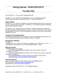
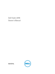
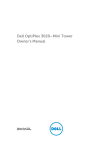
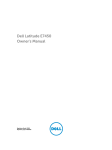
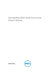
Dell Vostro 470
Owner's Manual
Regulatory Model: D10M
Regulatory Type: D10M002
Notes, Cautions, and Warnings
NOTE: A NOTE indicates important information that helps you make better use of your computer.
CAUTION: A CAUTION indicates potential damage to hardware or loss of data if instructions are not followed.
WARNING: A WARNING indicates a potential for property damage, personal injury, or death.
Information in this publication is subject to change without notice.
© 2012 Dell Inc. All rights reserved.
Reproduction of these materials in any manner whatsoever without the written permission of Dell Inc. is strictly forbidden.
Trademarks used in this text: Dell™, the DELL logo, Dell Precision™, Precision ON™,ExpressCharge™, Latitude™, Latitude ON™,
OptiPlex™, Vostro™, and Wi-Fi Catcher™ are trademarks of Dell Inc. Intel®, Pentium®, Xeon®, Core™, Atom™, Centrino®, and Celeron®
are registered trademarks or trademarks of Intel Corporation in the U.S. and other countries. AMD® is a registered trademark and
AMD Opteron™, AMD Phenom™, AMD Sempron™, AMD Athlon™, ATI Radeon™, and ATI FirePro™ are trademarks of Advanced Micro
Devices, Inc. Microsoft®, Windows®, MS-DOS®, Windows Vista®, the Windows Vista start button, and Office Outlook® are either
trademarks or registered trademarks of Microsoft Corporation in the United States and/or other countries. Blu-ray Disc™ is a trademark
owned by the Blu-ray Disc Association (BDA) and licensed for use on discs and players. The Bluetooth® word mark is a registered
trademark and owned by the Bluetooth® SIG, Inc. and any use of such mark by Dell Inc. is under license. Wi-Fi® is a registered
trademark of Wireless Ethernet Compatibility Alliance, Inc.
Other trademarks and trade names may be used in this publication to refer to either the entities claiming the marks and names or their
products, Dell Inc. disclaims any proprietary interest in trademarks and trade names other than its own.
2012 – 03
Rev. A00
Contents
Notes, Cautions, and Warnings...................................................................................................2
1 Working on Your Computer.......................................................................................................5
Before Working Inside Your Computer.....................................................................................................................5
Recommended Tools................................................................................................................................................6
Turning Off Your Computer.......................................................................................................................................6
After Working Inside Your Computer........................................................................................................................6
2 Removing The Cover...................................................................................................................7
Installing The Cover..................................................................................................................................................8
3 Removing The Memory..............................................................................................................9
Installing The Memory..............................................................................................................................................9
4 Removing The Expansion Card ..............................................................................................11
Installing The Expansion Card................................................................................................................................12
5 Removing The Optical Disk Drive...........................................................................................13
Installing The Optical Disk Drive.............................................................................................................................14
6 Removing The Hard Disk Drive...............................................................................................15
Installing The Hard Disk Drive................................................................................................................................16
7 Removing The Memory Card Reader.....................................................................................19
Installing The Memory Card Reader.......................................................................................................................20
8 Removing The Rear System Fan.............................................................................................21
Installing The Rear System Fan..............................................................................................................................22
9 Removing The Coin-Cell Battery.............................................................................................23
Installing The Coin-Cell Battery..............................................................................................................................23
10 Removing The Heat Sink........................................................................................................25
Installing The Heat Sink..........................................................................................................................................26
11 Removing The Processor.......................................................................................................27
Installing The Processor.........................................................................................................................................27
12 Removing The Power Supply Unit........................................................................................29
Installing The Power Supply Unit............................................................................................................................32
13 Removing The System Board................................................................................................33
Installing The System Board...................................................................................................................................35
14 Removing The Front Bezel.....................................................................................................37
Installing The Front Bezel.......................................................................................................................................38
15 Removing The WLAN Card....................................................................................................39
Installing The WLAN Card......................................................................................................................................40
16 Removing The Power Switch And The Hard Drive Activity LED.....................................41
Installing The Power Switch And The Hard Drive Activity LED..............................................................................42
17 Removing The Front Audio Module......................................................................................45
Installing The Front Audio Module..........................................................................................................................46
18 Removing The Front USB Module........................................................................................47
Installing The Front USB Module............................................................................................................................47
19 System Setup Overview.........................................................................................................49
Entering System Setup............................................................................................................................................49
System Setup Screens............................................................................................................................................49
System Setup Options.............................................................................................................................................50
Main.................................................................................................................................................................50
Advanced.........................................................................................................................................................51
Security............................................................................................................................................................53
Boot..................................................................................................................................................................53
Exit....................................................................................................................................................................53
20 Diagnostic Error Messages...................................................................................................55
Diagnostic Beep Codes..........................................................................................................................................56
System Messages...................................................................................................................................................56
21 Specifications..........................................................................................................................59
22 Contacting Dell........................................................................................................................63
Contacting Dell.......................................................................................................................................................63
Working on Your Computer
1
Before Working Inside Your Computer
Use the following safety guidelines to help protect your computer from potential damage and to help to ensure your
personal safety. Unless otherwise noted, each procedure included in this document assumes that the following
conditions exist:
•
You have read the safety information that shipped with your computer.
•
A component can be replaced or--if purchased separately--installed by performing the removal procedure in
reverse order.
WARNING: Before working inside your computer, read the safety information that shipped with your computer. For
additional safety best practices information, see the Regulatory Compliance Homepage at www.dell.com/
regulatory_compliance.
CAUTION: Many repairs may only be done by a certified service technician. You should only perform
troubleshooting and simple repairs as authorized in your product documentation, or as directed by the online or
telephone service and support team. Damage due to servicing that is not authorized by Dell is not covered by your
warranty. Read and follow the safety instructions that came with the product.
CAUTION: To avoid electrostatic discharge, ground yourself by using a wrist grounding strap or by periodically
touching an unpainted metal surface, such as a connector on the back of the computer.
CAUTION: Handle components and cards with care. Do not touch the components or contacts on a card. Hold a
card by its edges or by its metal mounting bracket. Hold a component such as a processor by its edges, not by its
pins.
CAUTION: When you disconnect a cable, pull on its connector or on its pull-tab, not on the cable itself. Some
cables have connectors with locking tabs; if you are disconnecting this type of cable, press in on the locking tabs
before you disconnect the cable. As you pull connectors apart, keep them evenly aligned to avoid bending any
connector pins. Also, before you connect a cable, ensure that both connectors are correctly oriented and aligned.
NOTE: The color of your computer and certain components may appear differently than shown in this document.
To avoid damaging your computer, perform the following steps before you begin working inside the computer.
1.
Ensure that your work surface is flat and clean to prevent the computer cover from being scratched.
2.
Turn off your computer (see Turning Off Your Computer).
CAUTION: To disconnect a network cable, first unplug the cable from your computer and then unplug the cable
from the network device.
3.
Disconnect all network cables from the computer.
4.
Disconnect your computer and all attached devices from their electrical outlets.
5.
Press and hold the power button while the computer is unplugged to ground the system board.
6.
Remove the cover.
5
CAUTION: Before touching anything inside your computer, ground yourself by touching an unpainted metal
surface, such as the metal at the back of the computer. While you work, periodically touch an unpainted metal
surface to dissipate static electricity, which could harm internal components.
Recommended Tools
The procedures in this document may require the following tools:
•
Small flat-blade screwdriver
•
#0 Phillips screwdriver
•
#1 Phillips screwdriver
•
Small plastic scribe
•
Flash BIOS update program CD
Turning Off Your Computer
CAUTION: To avoid losing data, save and close all open files and exit all open programs before you turn off your
computer.
1.
Shut down the operating system:
–
In Windows Vista :
, then click the arrow in the lower-right corner of the Start menu as shown below, and then
Click Start
click Shut Down.
–
In Windows XP:
Click Start → Turn Off Computer → Turn Off . The computer turns off after the operating system shutdown
process is complete.
2.
Ensure that the computer and all attached devices are turned off. If your computer and attached devices did not
automatically turn off when you shut down your operating system, press and hold the power button for about 4
seconds to turn them off.
After Working Inside Your Computer
After you complete any replacement procedure, ensure you connect any external devices, cards, and cables before
turning on your computer.
1.
Replace the cover.
CAUTION: To connect a network cable, first plug the cable into the network device and then plug it into the
computer.
2.
Connect any telephone or network cables to your computer.
3.
Connect your computer and all attached devices to their electrical outlets.
4.
Turn on your computer.
5.
Verify that the computer works correctly by running the Dell Diagnostics.
6
Removing The Cover
1.
Follow the procedures in Before working Inside your computer.
2.
Remove the two thumbscrews securing the computer cover to the computer.
2
Figure 1.
3.
Slide the computer cover towards the back of the computer, and then remove it from the computer.
Figure 2.
4.
Lift the computer cover away from the computer.
7
Figure 3.
Installing The Cover
1.
Place the computer cover on the computer and slide it inwards from the back of the computer.
2.
Replace and tighten the thumbscrews that secure the computer cover on the computer.
3.
Follow the procedures in After Working Inside Your Computer.
8
Removing The Memory
1.
Follow the procedures in Before Working Inside Your Computer.
2.
Remove the cover.
3.
Press down on the memory retaining tabs on each side of the memory modules and lift the memory module
upwards to remove it from the computer.
3
Figure 4.
Installing The Memory
1.
Align the notch on the memory-card with the tab in the system-board connector.
2.
Insert the memory module into the memory socket.
3.
Press down on the memory module until the securing clips secure the memory in place.
4.
Install the cover.
5.
Follow the procedures in After Working Inside Your Computer.
9
10
Removing The Expansion Card
1.
Follow the procedures in Before Working Inside Your Computer.
2.
Remove the cover.
3.
Press down on the blue retainer tab in an outward direction and push the retention panel downwards.
4
Figure 5.
4.
Press down the latch and pull the expansion card away from the computer.
Figure 6.
11
Installing The Expansion Card
1.
Push the expansion card into the card slot and secure the latch.
2.
Install the expansion card retainer module to the chassis.
3.
Install the cover.
4.
Follow the procedures in After Working Inside Your Computer.
12
Removing The Optical Disk Drive
1.
Follow the procedures in Before Working Inside Your Computer.
2.
Remove the cover.
3.
Disconnect the power cable and the data cable from the back of the optical drive.
5
Figure 7.
4.
Remove the screws that secure the optical drive to the drive cage.
Figure 8.
5.
Slide out the optical drive through the front of the computer.
13
Figure 9.
Installing The Optical Disk Drive
1.
Slide the optical drive in through the front of the computer.
2.
Replace the screws that secure the optical drive to the drive cage.
3.
Connect the power cable and data cable to the optical drive.
4.
Install the cover.
5.
Follow the procedures in After Working Inside Your Computer.
14
Removing The Hard Disk Drive
1.
Follow the procedures in Before Working Inside Your Computer.
2.
Remove the cover.
3.
Disconnect the power cable and the data cable from the back of the hard drive.
6
Figure 10.
4.
Remove the screws that secure the hard drive cage to the chassis.
Figure 11.
15
5.
Slide out the hard drive by lifting it in an upward direction.
Figure 12.
6.
Remove the screws that secure the hard drive to the drive cage.
Figure 13.
7.
Pry the hard drive cage in the direction indicated to remove the hard drive from the hard drive cage.
Figure 14.
Installing The Hard Disk Drive
1.
Tighten the screws that secure the hard drive to the drive cage.
2.
Place the hard drive into the slot and tighten the screws that secure the hard drive cage to the chassis.
16
3.
Connect the power cable and data cable to the hard drive.
4.
Install the cover.
5.
Follow the procedures in After Working Inside Your Computer.
17
18
Removing The Memory Card Reader
1.
Follow the procedures in Before Working Inside Your Computer.
2.
Remove the cover.
3.
Disconnect the memory card cable from the system board.
7
Figure 15.
4.
Unroute the memory card reader cable from the retention clip.
Figure 16.
5.
Remove the screws that secure the memory card reader to the drive cage.
19
Figure 17.
6.
Slide the multimedia card reader out through the front of the computer.
Figure 18.
Installing The Memory Card Reader
1.
Slide the memory card-reader in through the front of the computer.
2.
Replace and tighten the screws that secure the multimedia card-reader to the drive cage.
3.
Route the memory card reader cable through the retention clip.
4.
Connect the memory card reader cable to the system board connector.
5.
Install the cover.
6.
Follow the procedures in After Working Inside Your Computer.
20
Removing The Rear System Fan
1.
Follow the procedures in Before Working Inside Your Computer.
2.
Remove the cover.
3.
Disconnect the fan cable from the system board.
8
Figure 19.
4.
Remove the screws that secure the fan to the chassis and lift the fan out of the computer.
Figure 20.
21
Installing The Rear System Fan
1.
Place the fan towards the center of the computer into the chassis.
2.
While holding the chassis fan in place, replace the screws that secure the fan to the chassis.
3.
Reconnect the fan cable to the system board.
4.
Install the cover.
5.
Follow the procedures in After Working Inside Your Computer.
22
Removing The Coin-Cell Battery
1.
Follow the procedures in Before Working Inside Your Computer.
2.
Remove the cover.
3.
Remove the expansion card.
4.
Press the release latch away from the battery and pop up the battery from the socket on the system board.
9
Figure 21.
Installing The Coin-Cell Battery
1.
Insert the coin-cell battery into the slot.
2.
Install the expansion card.
3.
Install the cover.
4.
Follow the procedures in After Working Inside Your Computer.
23
24
Removing The Heat Sink
1.
Follow the procedures in Before Working Inside Your Computer.
2.
Remove the cover.
3.
Disconnect the heat sink fan cable from the system board.
10
Figure 22.
4.
Remove the screws that secure the heat sink assembly to the system board and remove the heat sink from the
computer.
Figure 23.
25
Installing The Heat Sink
1.
Connect the heat sink fan cable to the system board.
2.
Install the screws that secure the heat sink assembly to the system board.
3.
Install the cover.
4.
Follow the procedures in After Working Inside Your Computer.
26
Removing The Processor
11
1.
Follow the procedures in Before Working Inside Your Computer.
2.
Remove the cover.
3.
Remove the heat sink assembly.
4.
Push the processor release lever down and then press it outward to release it from the retention hook that secures
it.
5.
Raise the processor cover and lift up the processor to remove it from the computer.
Figure 24.
Installing The Processor
1.
Install the processor into the socket.
2.
Press down the processor cover to secure it inside the socket.
3.
Push the release lever down and then press it inward to hold the retention hook that secures it.
4.
Install the heat sink assembly.
5.
Install the cover.
6.
Follow the procedures in After Working Inside Your Computer.
27
28
Removing The Power Supply Unit
1.
Follow the procedures in Before Working Inside Your Computer.
2.
Remove the cover.
3.
Press the release latch and lift up the cable holder to disconnect it from the latch on the system board.
12
Figure 25.
4.
Disconnect the power supply cable from the back of the hard drive.
Figure 26.
29
5.
Disconnect the power supply cable from the back of the optical drive.
Figure 27.
6.
Disconnect the power supply cable from the system board.
Figure 28.
7.
30
Remove the screws that secure the power supply unit to the computer chassis.
Figure 29.
8.
Push the blue release tab beside the power supply and slide the power supply unit towards the front of the
computer.
Figure 30.
9.
Lift the power supply unit out of the computer.
31
Figure 31.
Installing The Power Supply Unit
1.
Install the power supply unit into the computer.
2.
Slide the power supply unit towards the back of the computer till it snaps into place.
3.
Install the screws that secure the power supply unit to the computer.
4.
Connect all the power supply cables to the system board and drives.
5.
Install the cover.
6.
Follow the procedures in After Working Inside Your Computer.
32
Removing The System Board
1.
Follow the procedures in Before Working Inside Your Computer.
2.
Remove the cover.
3.
Remove the memory modules.
4.
Remove the expansion card.
5.
Remove the heat sink.
6.
Remove the processor.
7.
Remove the hard drive.
8.
Remove the optical drive.
9.
Remove the memory card reader.
13
10. Disconnect and unthread all the cables on the system board.
Figure 32.
11. Remove the screws that secure the system board to the computer chassis.
33
Figure 33.
12. Slide the system board towards the front of the computer.
Figure 34.
13. Lift the system board out of the computer.
34
Figure 35.
Installing The System Board
1.
Place the system board into the computer.
2.
Slide the system board towards the back of the computer.
3.
Install the screws that secure the system board to the computer chassis.
4.
Thread and connect all the cables to the system board.
5.
Install the processor.
6.
Install the heat sink.
7.
Install the memory modules.
8.
Install the optical drive.
9.
Install the hard drive.
10. Install the expansion card.
11. Install the cover.
12. Follow the procedures in After Working Inside Your Computer.
35
36
Removing The Front Bezel
1.
Follow the procedures in Before Working Inside Your Computer.
2.
Remove the cover.
3.
Lift the retention clips slightly upward to release that edge of the bezel from the chassis.
14
Figure 36.
4.
Remove the front bezel from the computer.
Figure 37.
37
Installing The Front Bezel
1.
Rotate the bezel towards the computer to place the hooks on the chassis.
2.
Place the retention clips downwards to lock the edge of the bezel on the chassis.
3.
Install the cover.
4.
Follow the procedures in After Working Inside Your Computer.
38
Removing The WLAN Card
1.
Follow the procedures in Before Working Inside Your Computer.
2.
Remove the cover.
3.
Remove the front bezel.
4.
Disconnect the antenna cables from the WLAN card.
5.
Remove the screw that secures the WLAN card and remove it from the card slot.
15
Figure 38.
6.
Release the WLAN card cable from the routing clips and lift them in an upward direction.
Figure 39.
7.
Remove the WLAN card cable from the computer by sliding it around from the front of the computer.
39
Figure 40.
Installing The WLAN Card
1.
Route the WLAN card cable around the securing clips.
2.
Slide the WLAN card into its slot.
3.
Tighten the screws to secure the WLAN card in place.
4.
Connect the antenna cables according to the color code on the WLAN card.
5.
Install the front bezel.
6.
Install the cover.
7.
Follow the procedures in After Working Inside Your Computer.
40
16
Removing The Power Switch And The Hard Drive
Activity LED
1.
Follow the procedures in Before Working Inside Your Computer.
2.
Remove the cover.
3.
Remove the front bezel.
4.
Disconnect the power switch cable from the system board.
Figure 41.
5.
Unthread the power switch cable from the routing clips.
Figure 42.
6.
Unthread the hard drive activity LED cable from the routing clips near the front bezel.
41
Figure 43.
7.
Press the hard drive activity LED on the sides to release it and then push in the hard drive activity LED to remove it
from the front bezel.
Figure 44.
8.
Press the Power switch on the sides to release it and then push in the power switch to remove it from the front
bezel.
Figure 45.
Installing The Power Switch And The Hard Drive Activity LED
1.
Thread the power switch cable and the hard drive activity LED cable through the routing clips.
2.
Connect the power-button cable to the system board.
3.
Insert the power button and hard drive activity LED into the front of the computer.
4.
Install the front bezel.
5.
Install the cover.
42
6.
Follow the procedures in After Working Inside Your Computer.
43
44
Removing The Front Audio Module
1.
Follow the procedures in Before Working Inside Your Computer.
2.
Remove the cover.
3.
Remove the front bezel.
4.
Disconnect the front audio module cable from the system board.
17
Figure 46.
5.
Remove the front audio module routing cable through the routing clips on the chassis.
Figure 47.
45
6.
Remove the screw that secures the front audio module to the front bezel and remove the front audio module from
the computer.
Figure 48.
Installing The Front Audio Module
1.
Place the front audio module on the front bezel and install the screw that secures it.
2.
Route the front audio module cable through the routing clips on the chassis.
3.
Connect the front audio module cable to its connector on the system board.
4.
Install the front bezel.
5.
Install the cover.
6.
Follow the procedures in After Working Inside Your Computer.
46
Removing The Front USB Module
1.
Follow the procedures in Before Working Inside Your Computer.
2.
Remove the cover.
3.
Remove the front bezel.
4.
Disconnect the front USB module data cable and the power cable from the system board.
18
Figure 49.
5.
Remove the screw that secures the front USB module to the front bezel and remove the front USB module from the
computer.
Figure 50.
Installing The Front USB Module
1.
Place the front USB module on the front bezel and install the screw that secures the front USB module to the front
bezel.
2.
Connect the front USB module cable to the system board.
3.
Install the front bezel.
47
4.
Install the cover.
5.
Follow the procedures in After Working Inside Your Computer.
48
19
System Setup Overview
System Setup allows you to:
•
change the system configuration information after you add, change, or remove any hardware in your computer.
•
set or change a user-selectable option such as the user password.
•
read the current amount of memory or set the type of hard drive installed.
Before you use System Setup, it is recommended that you write down the System Setup screen information for future
reference.
CAUTION: Unless you are an expert computer user, do not change the settings for this program. Certain changes
can cause your computer to work incorrectly.
Entering System Setup
1.
Turn on (or restart) your computer.
2.
When the blue DELL logo is displayed, you must watch for the F2 prompt to appear.
3.
Once the F2 prompt appears, press <F2> immediately.
NOTE: The F2 prompt indicates that the keyboard has initialized. This prompt can appear very quickly, so you must
watch for it to display, and then press <F2> . If you press <F2> before you are prompted, this keystroke will be lost.
4.
If you wait too long and the operating system logo appears, continue to wait until you see the Microsoft Windows
desktop. Then, shut down your computer and try again.
System Setup Screens
Table 1. System Setup Screens
Menu — Appears on top of the System Setup window. This field provides a menu to access the System Setup options.
Press < Left Arrow > and < Right Arrow > keys to navigate. As a Menu option is highlighted, the Options List lists the
options that define the hardware installed on your computer.
Options List — Appears on the left
side of the System Setup window. The
field lists features that define the
configuration of your computer,
including installed hardware, power
conservation, and security features.
Scroll up and down the list with the
up- and down-arrow keys. As an
option is highlighted, the Options Field
displays the option's current and
available settings.
Options Field — Appears on the right
side of Options List and contains
information about each option listed in
the Options List. In this field you can
view information about your computer
and make changes to your current
settings. Press < Enter> to make
changes to your current settings.
Press <ESC> to return to the Options
List.
Help — Appears on the right side of
the System Setup window and
contains help information about the
option selected in Options List.
49
NOTE: Not all settings listed in the
Options Field are changeable.
Key Functions— Appears below the Options Field and lists keys and their functions within the active system setup
field.
Use the following keys to navigate through the System Setup screens:
Table 2. System Setup Screens Navigation
Keystroke
Action
< F2 >
Displays information on any selected item in the System
Setup.
< Esc >
Exit from current view or switch the current view to the
Exit page in the System Setup.
< Up Arrow > or < Down Arrow >
Select an item to display.
< Left Arrow > or < Right Arrow >
Select a menu to display.
– or +
< Enter >
Change existing item value.
Select the sub menu or execute command.
< F9 >
Load setup default.
< F10 >
Save current configuration and exit System Setup.
System Setup Options
Main
The Main tab lists out the primary hardware features of the computer. The table below defines the function of each
option.
Table 3. System Information
Option
Description
BIOS Revision
Displays the BIOS revision.
BIOS Build Date
Displays the BIOS build date.
System Name
Displays the computer model number.
System Time
Re-sets the time on the computer's internal
clock.
System Date
Re-sets the date on the computer's internal
calendar.
Service Tag
Displays the service tag of your computer.
Service Tag Input
Enables the user to input the service tag.
Asset Tag
Displays the asset tag of your computer.
System Information
50
Option
Description
Option
Description
Processor Type
Displays the type of processor.
Processor ID
Displays the processor ID.
Processor Core Count
Displays the number of processor cores.
L1 Cache Size
Displays the processor L1 cache size.
L2 Cache Size
Displays the processor L2 cache size.
L3 Cache Size
Displays the processor L3 cache size.
Option
Description
Memory Installed
Displays the total computer memory.
Memory Available
Displays the available computer memory.
Memory Speed
Displays the memory speed.
Memory Technology
Displays the type and technology.
Option
Description
SATA 1
Displays the model number and capacity of
the hard drive.
SATA 2
Displays the model number and capacity of
the hard drive.
SATA 3
Displays the model number and capacity of
the hard drive.
eSATA /mSATA
Displays the model number and capacity of an
eSATA or mSATA hard drive.
Processor Information
Memory Information
SATA Information
Advanced
The Advanced tab allows you to set various functions that affect the performance of the computer. The table below
defines the function of each option and its default value.
Table 4. CPU Configuration
Option
Description
Intel Hyper-Threading Technology
Enable or disable processor hyperthreading.
Default: Enabled
Intel SpeedStep
Enable or disable the Intel SpeedStep
feature.
Default: Enabled
51
Option
Description
Intel Virtualization Technology
Enable or disable the Intel
Virtualization feature.
CPU XD Support
Enable or disable the CPU XD feature. Default: Enabled
Limit CPUID Value
Enable or disable the Limit CPUID
Value feature.
Default: Enabled
Multi Core Support
Displays the number of active cores.
Default: Enabled
Intel Turbo Boost Technology
Enable or disable the Intel Boost
Technology feature.
Default: Enabled
AMD Cool 'N' Quiet
Enable or disable the AMD Cool 'N'
Quiet Technology feature.
Default: Enabled
Secure Virtual Machine Mode
Enable or disable the Secure Virtual
Machine Mode (SVM).
Default: Enabled
Default: Enabled
Table 5. CPU Configuration
USB Configuration
Option
Description
Front USB Ports
Enable or disable the Front USB Ports. Default: Enabled
Rear USB Ports
Enable or disable the Rear USB Ports. Default: Enabled
Side USB Ports
Enable or disable the Side USB Ports.
Default: Enabled
Table 6. Onboard Device Configuration
Onboard Device Configuration
Option
Description
Onboard Audio Controller
Enable or disable the onboard audio
controller.
Default: Enabled
SATA Mode
Allows you to choose the SATA
operation mode.
Default: AHCI
Intel Multi-Display
Enable or disable the Intel MultiDisplay feature.
Default: Disabled
Onboard LAN Controller
Enable or disable the onboard LAN
controller.
Default: Enabled
Onboard LAN Boot ROM
Enable or disable the onboard LAN
boot ROM.
Default: Disabled
Onboard 1394 Controller
Enable or disable the USB controller.
Default: Enabled
Table 7. Power Management
Power Management
Option
52
Description
Power Management
Wake Up by Integrated LAN/WLAN
Enable or Disable the Wake Up by
Integrated LAN/WLAN feature.
Default: Disabled
AC Recovery
Allows the computer to restore the AC Default: Power Off
power Loss.
USB PowerShare in S4/S5 State
Allows the computer to be remotely
turned on.
Default: Enabled
USB PowerShare in Sleep State
Enable or disable the USB ports in
sleep state.
Default: Normal
Auto Power On
Enable or disable the computer to
power on automatically.
Default: Disabled
Auto Power On Mode
Enable or disable the computer to
power on at a selected day.
Every Day ; Selected Day
Auto Power On Date
Enable or disable the computer to
power on at a selected date.
15
Auto Power On Time
Enable or disable the computer to
power on at a selected time.
Hour : 0–23 ; Minutes: 0–59 ; Second ;
0–59
Security
The Security tab displays the security status and allows you to manage the security features of the computer.
Table 8. Security
Supervisor Password Status
Specifies whether an admin password has been assigned.
User Password Status
Specifies whether an user password has been assigned.
Set Supervisor Password
Allows you to set an admin password.
User Access Level
Specifies the user access level.
Set User Password
Allows you to set an user password.
Password Check
Allows you to check the password while invoking setup.
Boot
The Boot tab allows you to change the boot sequence.
Exit
This section allows you to save, discard, and load default settings before exiting from System Setup.
53
54
20
Diagnostic Error Messages
If the computer has an issue or error, it may display a System Message that will help the user identify the cause and
action needed to resolve the issue. If the message received is not listed in the following examples, see the
documentation for either the operating system or the program that was running when the message appeared.
Diagnostic Error Messages
Description
Alert! Previous attempts at booting this system have failed The computer failed to complete the boot routine three
at checkpoint [nnnn]. For help in resolving this problem,
consecutive times for the same error.
please note this checkpoint and contact Dell Technical
Support.
System fan failure
Possible fan failure
CPU fan failure
CPU fan has failed
Hard-disk drive failure
Possible hard disk drive failure during POST.
Hard-disk drive read failure
Possible hard disk drive failure during HDD boot test.
Keyboard failure
Keyboard failure or loose cable. If reseating the cable
does not solve the problem, replace the keyboard.
RTC is reset, BIOS Setup default has been loaded. Strike
the F1 key to continue, F2 to run the setup utility.
RTC Jumper may be wrongly set.
No boot device available
No bootable partition on hard disk drive, the hard disk
drive cable is loose, or no bootable device exists.
•
If the hard drive is your boot device, ensure that
the cables are connected and that the drive is
installed properly and partitioned as a boot
device.
•
Enter system setup and ensure that the boot
sequence information is correct.
No timer tick interrupt
A chip on the system board might be malfunctioning or
motherboard failure
USB over current error
Disconnect the USB device. The USB device needs more
power for it to function properly. Use an external power
source to connect the USB device, or if the device has
two USB cables, connect both of them.
CAUTION - Hard Drive SELF MONITORING SYSTEM has
reported that a parameter has exceeded its normal
operating range. Dell recommends that you back up your
data regularly. A parameter out of range may or may not
indicate a potential hard drive problem.
S.M.A.R.T error, possible hard disk drive failure.
55
Diagnostic Beep Codes
The computer may emit a series of beeps during start-up if the display cannot show errors or problems. These series of
beeps, called beep codes, identify various problems. The delay between each beep is 300 ms, the delay between each
set of beeps is 3 seconds, and the beep sound lasts 300 ms. After each beep and each set of beeps, the BIOS should
detect if the user presses the power button. If so, BIOS will jump out from looping and execute the normal shutdown
process and power system.
Code Cause and Troubleshooting Steps
1
BIOS ROM checksum in progress or failure
System board failure, covers BIOS corruption or ROM error.
2
No RAM detected.
No memory detected
3
Chipset Error (North and South Bridge Chipset, DMA/IMR/ Timer Error) , Time-Of-Day Clock test failure , Gate
A20 failure , Super I/O chip failure , Keyboard controller test failure.
System board failure.
4
RAM Read/Write failure.
Memory failure.
5
Real-time clock power fail.
CMOS battery failure.
6
Video BIOS test failure.
Video card failure.
7
Processor failure.
Processor failure.
System Messages
If your computer has an issue or error, it may display a System Message that will help you identify the cause and action
needed to resolve the issue.
NOTE: If the message received is not listed in the following examples, see the documentation for either the
operating system or the program that was running when the message appeared.
Table 9. System Messages
System Message
Description
Alert! Previous attempts at booting this system have failed at
checkpoint [nnnn]. For help in resolving this problem, please
note this checkpoint and contact Dell Technical Support
The computer failed to complete the boot routine
three consecutive times for the same error.
CMOS checksum error
Possible motherboard failure or RTC battery low.
CPU fan failure
CPU fan has failed.
System fan failure
System fan has failed.
Hard-disk drive failure
Possible hard disk drive failure during POST.
56
System Message
Description
Hard-disk drive read failure
Possible hard disk drive failure during HDD boot test.
Keyboard failure
Keyboard failure or loose cable. If re-seating the
cable does not solve the problem, replace the
keyboard
No boot device available
No bootable partition on hard disk drive, the hard disk
drive cable is loose, or no bootable device exists.
•
•
If the hard drive is your boot device, ensure
that the cables are connected and that the
drive is installed properly and partitioned as a
boot device.
Enter system setup and ensure that the boot
sequence information is correct.
No timer tick interrupt
A chip on the system board might be malfunctioning
or motherboard failure.
USB over current error
Disconnect the USB device. The USB device needs
more power for it to function properly. Use an external
power source to connect the USB device, or if the
device has two USB cables, connect both of them.
CAUTION - Hard Drive SELF MONITORING SYSTEM has
reported that a parameter has exceeded its normal operating
range. Dell recommends that you back up your data regularly.
A parameter out of range may or may not indicate a potential
hard drive problem
S.M.A.R.T error, possible hard disk drive failure.
57
58
21
Specifications
NOTE: Offerings may vary by region. The following specifications are only those required by law to ship with your
computer. For more information regarding the configuration of your computer, click Start → Help and Support and
select the option to view information about your computer.
Table 10. System Information
System Information
Model
Vostro 470
Processor
Intel Core i3 (2nd Generation)
Intel Core i5 (3rd Generation)
Intel Core i7 (3rd Generation)
L2 cache
256 KB
L3 cache
up to 8 MB
System chipset
Intel H77 Express Chipset
DMI speed
5.0 GT/s
Processor data width
64 bits
RAID support (internal SATA drives only)
RAID 0, RAID 1, RAID 5 and RAID 10
Table 11. Dimensions
Dimensions
Height
without base
360.00 mm (14.17 inches)
with base
362.90 mm (14.29 inches)
Width
175.00 mm (6.89 inches)
Depth
445.00 mm (17.52 inches)
Weight
9.66 kg – 11.22 kg (21.30 lb – 24.74 lb)
Table 12. Memory
Memory
Connectors
four internally-accessible DDR3 DIMM sockets
Type
unbuffered, Non-ECC, quad‑channel DDR3
Speed
up to 1600 MHz
59
Memory
Capacities
2 GB, 4 GB, 8 GB, 24 GB, and 32 GB.
NOTE: The capacities supported by your computer may
vary depending on the configuration ordered.
Configurations supported
2 GB, 4 GB, 8 GB, 12 GB, and 16 GB.
Minimum memory
2 GB
Maximum memory
32 GB
Table 13. Video
Video
Video controller
NA
Integrated
Intel HD Graphics 2500/4000
Discrete
one PCI Express x16, single-width, full length graphics card.
Video memory
Integrated
upto 1024 MB
Discrete
upto 2 GB discrete video memory
NOTE: The available video memory will depend on the
graphics card installed on the computer.
Table 14. Ports
Ports
Back panel Ports
Network Adapter
one RJ–45 port
USB
four 4-pin USB 2.0-compliant ports
two 9-pin USB 3.0-compliant ports
Audio
five audio output/headphone ports
one optical S/PDIF port
one audio input/microphone port
Video
one VGA port
one HDMI port
Front Panel Ports
USB
two 9-pin USB 3.0-compliant ports
Table 15. Communications
Communications
Network adapter
60
10/100/1000 Mbps integrated network card
Communications
Wireless
Wi-Fi and Bluetooth wireless technology
Table 16. Audio
Audio
Type
integrated 7.1 channel, High Definition Audio with S/PDIF
support
Controller
ALC3800-CG
Table 17. Drives
Drives
Externally accessible
two 5.25-inch drive bays for a Blu-ray Disc combo
(optional), Blu-ray Disc Writer (optional), or DVD+/-RW
Internally accessible
two 3.5-inch drive bays for SATA hard drives
one mSATA SSD drive (optional)
Table 18. Expansion Bus
Expansion Bus
PCI Express x1
Connectors
three
Connector size
36-pin
PCI Express x16
Connectors
one
Connector size
164-pin
PCI-E mini-card
Connectors
one
Connector size
52-pin
Table 19. Power
Power
Input voltage
100-127 VAC / 200-240 VAC
Input frequency
50/60 Hz
Rated input current
8.0 A/4.0 A
61
Table 20. Environmental
Environmental
Temperature:
Operating
10 °C to 35 °C (50 °F to 95 °F)
Storage
–10 °C to 45 °C (–14 °F to 113 °F)
Relative humidity:
20 % to 80 % (noncondensing)
Maximum vibration:
Operating
0.25 Grms
Non-Operating
2.20 Grms
Maximum shock:
Operating
40 G for 2 ms with a change in velocity of 20 inches/s (51 cm/s)
Non-Operating
50 G for 26 ms with a change in velocity of 320 inches/s (813 cm/s)
Altitude:
Operating
–15.20 m to 3048 m (–50 ft to 10,000 ft)
Storage
–15.20 m to 10,668 m (–50 ft to 35,000 ft)
Airborne contaminant level
62
G2 or lower as defined by ISA-S71.04-1985
Contacting Dell
22
Contacting Dell
NOTE: If you do not have an active Internet connection, you can find contact information on your purchase invoice,
packing slip, bill, or Dell product catalog.
Dell provides several online and telephone-based support and service options. Availability varies by country and
product, and some services may not be available in your area. To contact Dell for sales, technical support, or customer
service issues:
1.
Visit support.dell.com.
2.
Select your support category.
3.
If you are not a U.S. customer, select your country code at the bottom of the support.dell.com page, or select All to
see more choices.
4.
Select the appropriate service or support link based on your need.
63