1
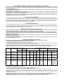
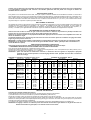
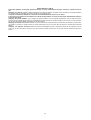
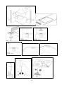
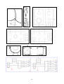
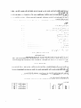
(GB) INSTRUCTIONS FOR THE INSTALLATION, MAINTENANCE AND USE OF FIXED HOBS WITH GAS OR MIXED SUPPLY 59X50 cm (TYPE P61/P61V) 86X50 cm (TYPE P91/P91V) (FR) INSTRUCTIONS POUR L'INSTALLATION, L'ENTRETIEN ET L'UTILISATION DES TABLES DE CUISSON ENCASTRABLES GAZ ET MIXTES 59X50 cm (MODELE P61/P61V) 86X50 cm (MODELE P91/P91V) 310605 (GB) READ THE INSTRUCTION BOOKLET BEFORE INSTALLING AND USING THE APPLIANCE. These instructions are valid only for those countries which are indicated by their identification symbol on the front cover of the instruction booklet and on the label on the appliance. The manufacturer cannot be held responsible for any damage to things or persons caused by an incorrect installation or by incorrect use of the appliance. The manufacturer cannot be held responsible for any inaccuracies due to errors in printing or writing contained in this booklet. The appearance of the figures shown is also only approximate. The manufacturer reserves the right to make changes to his products when it is considered necessary and useful without effecting the essential features regarding safety and function. INDEX: TECHNICAL MANUAL FOR THE INSTALLER ........................................................................................................ pag. 2 Inserting the hob ......................................................................................................................................................... pag. 2 Fixing the hob – Advice about installation ................................................................................................................... pag. 2 Ventilation and airing of the premises – Connection to the gas supply ....................................................................... pag. 3 Adaptation to different types of gas ............................................................................................................................ pag. 3 Regulation of the burners ............................................................................................................................................ pag. 3 Connection to the electricity supply ............................................................................................................................. pag. 4 MAINTENANCE OF THE APPLIANCE – Replacing parts ........................................................................................ pag. 4 USE AND MAINTENANCE MANUAL ........................................................................................................................ pag. 4 Description of types of hobs ........................................................................................................................................ pag. 4 Use of the burners ....................................................................................................................................................... pag. 5 Cleaning of the appliance ............................................................................................................................................ pag. 5 Figures ........................................................................................................................................................................ pag. 12 Electrical Diagran ........................................................................................................................................................ pag. 13 THIS APPLIANCE HAS BEEN DESIGNED FOR NON PROFESSIONAL USE IN HOUSEHOLDS. This appliance is not intended for use by persons (including children) with reduced mental or motorial capacities or who have no experience and knowledge unless under supervision or instructed on use of the appliance by a person responsible for their safety. Children must be watched to ensure that they do not play with the appliance. The appliance is not constructed to operate with an external timer or other remote control system TECHNICAL MANUAL FOR THE INSTALLER INFORMATION FOR THE INSTALLER The installation, all regulations, changes and maintenance referred to in this part must only be carried out by qualified staff. A wrong installation can cause damage to persons, animals or things which the manufacturer cannot be held responsible for. The safety and automatic regulation devices on the appliances can only ever be changed by the manufacturer or by the supplier which has been authorised to do so. INSERTING THE HOB When you have removed the various adjustable parts from their internal and external packaging, check that the hob is intact. If you are in doubt do not use the appliance and contact the qualified staff. The parts which make up the packaging ( polystyrene, bags, boxes, nails etc. ), are dangerous objects and must be kept out of children’s reach. Taking into consideration the specific dimensions of the appliance (see table N°1), make an opening in the work surface (see figure): Hobs type P61/P61V (59x50 cm) P91/P91V (86x50 cm) with right angle corner Fig. 1. using the measurements indicated in table N°.1 The appliance must be classified in class 3 and thus it is subject to all the regulations indicated by the norms regarding these appliances. Table N°.1 P6 P9 W (cm) 57 84 D (cm) 48 48 L1 min (cm) L2 min (cm) L3 min (cm) L4 min (cm) 6 4 10 70 FIXING THE HOB In order to prevent liquids from accidentally leaking into the kitchen unit underneath the appliance is equipped with a special seal. To put on this seal follow the instructions below very carefully. 1) Stretch out the seal along the edge of the opening, taking care to overlap the joining points. (fig. 2). 2) Insert the hob into the opening in the kitchen unit. 3) With a screwdriver assemble the 4 plates A with the special screw B (fig. 3). 4) Move the plates along and fix them using screw B. 5) Reinsert the part of the seal on the outside of the hob. 2 IMPORTANT INFORMATION CONCERNING THE INSTALLATION OF THE APPLIANCE We inform the installer that this hob is of the Y type and thus it can be installed by itself, in an isolated position or inserted between two kitchen units or between one kitchen unit and a wall. Furthermore the back wall and surrounding surfaces must resist a temperature of 65 K. To prevent the plastic layer which covers the kitchen unit from ungluing, the glue used to join the two surfaces together must resist temperatures of up to 150 °C The installation of the appliance must be carried out according to the norms in force of the country concerned and the appliance must be installed in a well ventilated place. This appliance is not equipped with devices to remove the products of combustion. The appliance must therefore be connected following the norms for installation mentioned above. Special attention must be paid to the information below regarding aeration and ventilation of the premises. VENTILATION OF THE PREMISES To guarantee that the appliance works correctly it is necessary that the place where the appliance is installed is continuously ventilated. The volume of the premises must not be less than 25 m³ and the quantity of air needed must be based on the regular combustion of gas and on the ventilation of the premises. The natural flow of air will take place through permanent openings made in the wall of the premises to be ventilated: these openings will be connected to the outside and must have a minimum section of 100 cm² ( see Fig. 4 ). These openings must be made in such a way that they cannot be obstructed. POSITION AND VENTILATION The cooking appliances that use gas must always remove the products of combustion via a hood linked to chimneys, chimney flues or via a direct connection to the outside ( see Fig. 5A ). If it is not possible to fit a hood it is possible to use a fan, fitted on the window or facing directly outside, which operates when the appliance is in use. ( see Fig. 5B ). In this way the norms in force of the country concerned regarding the ventilation of premises are strictly followed. CONNECTING THE APPLIANCE TO THE GAS SUPPLY Before connecting the appliance to the gas supply you first need to remove the plastic protective plug for the gas supply which is inserted under pressure in the gas inlet connection. To remove the plug simply unscrew it. Then make sure that the details shown on the label on the lower part of the case are compatible with those of the gas supply. A label on the last page of this manual and on the lower part of the case indicates the conditions for regulating the appliance: type of gas and pressure used. IMPORTANT: This appliance must be installed in accordance with the norms in force of the country concerned and it must only be used in a well-ventilated place. ATTENTION: Remember that the gas inlet connection for the appliance is threaded 1/2 gas cylindrical male in accordance with the norms UNI-ISO 228-1. (Fig. 6) ADAPTING TO DIFFERENT TYPES OF GAS Before carrying out any maintenance work, disconnect the appliance from the gas and electric supply. - CHANGING THE NOZZLES FOR USE WITH OTHER TYPES OF GAS: To change the nozzles of the burners use the following procedure: Lift up the burners and unscrew the nozzles ( Fig. 7) using an adjustable spanner of 7 mm and change the nozzles with those designed for the new gas supply according to the information given in TABLE N° 2 shown below. ATTENTION: After carrying out the changes described above, the technician must put the label corresponding to the new gas supply on the appliance to take the place of the old label. This label is found in the bag containing spare nozzles. TABLE N°2: Adapting to different types of gas APPLIANCE CATEGORY: II2H3+ Burner Type of Gas Pressure Nozzle Nominal Charge Reduced Charge Diameter diameter by-pass 1/100mm mbar 1/100mm g/h l/h Kw kcal/h kw kcal/h No saf. safety Natural G20 20 77 95 1 860 0,3 258 27 27 Auxiliary Butane G30 28 50 73 1 860 0,3 258 27 27 Propane G31 37 50 71 1 860 0,3 258 27 27 SemiNatural G20 20 101 167 1,75 1505 0,44 378 34 31 Rapid Butane G30 28 66 127 1,75 1505 0,44 378 34 31 Propane G31 37 66 125 1,75 1505 0,44 378 34 31 Natural G20 20 129 286 3 2580 0,75 645 44 42 Rapid Butane G30 28 87 218 3 2580 0,75 645 44 42 Propane G31 37 87 214 3 2580 0,75 645 44 42 In 70 In 34reg Natural G20 20 476 5 4300 0,48 413 N.A. Out 110 out 65reg Dual In 46 In 34reg Butane G30 30 334 4,6 3956 0,48 413 N.A. Out 69 out 65reg In 46 In 34reg Propane G31 37 328 4,6 3956 0,48 413 N.A. Out 69 out 65reg REGULATION OF BURNERS: 1) Regulation of the "MINIMUM" on the burners To regulate the minimum on the burners carry out the following procedure indicated below: 1) Turn on the burner and put the knob onto position MINIMUM ( small flame ). 2) Remove the knob ( Fig. 8) of the tap which is set for standard pressure. The knob is found on the bar of the tap itself. 3) Beside the tap bar on the work top, use a small screwdriver that fits the screw (gold) found on the lower part of the tap (auxiliary, semirapid, rapid Fig. 8) (dual fig.9) and turn the fixing screw to the right or left until the flame of the burner is regulated in the most suitable way to MINIMUM. 4) Make sure that that the flame does not go out when changing the position quickly from MAXIMUM to the MINIMUM position. ATTENTION: The regulation described above can be carried out only with burners using methane gas and city gas ( where available), while with burners using liquid gas the screw must be fully screwed in, in a clockwise direction. 3 CONNECTION OF THE APPLIANCE TO THE ELECTRICITY SUPPLY: Connection to the electricity supply must be carried out according to the norms and indications of the law in force. Before carrying out the connection check that: - The electric charge of the system and the sockets are suitable for the maximum power of the appliance ( see label on the lower part of the case ). - The socket or system is equipped with an efficient earth connection according to the norms and indications of the law currently in force. No responsibility can be held if these indications are not respected. When the connection to the electricity supply is made with a socket. Fit onto the electric cable a standard plug ( if it is not provided ) which is appropriate for the charge indicated on the label. Connect up the wires according to the diagram in Fig. 10 taking care to respect the corresponding pairs listed below: letter L (phase) = brown coloured wire; letter N (neutral) = blue coloured wire; ” earth = green-yellow coloured wire; symbol” - The electric cable must be positioned so that it cannot reach a temperature of over 75 K at any point. - Do not use reducers, adapters or shunts for the connection as they could cause false contacts and subsequent dangerous overheating. When the connection is made directly with the electricity supply: - Make sure that there is a device to disconnect the appliance from the mains with a contact opening distance sufficient for complete disconnection in category III overvoltage conditions. - Place a single-pole switch between the appliance and the electricity supply. The switch must be of a suitable charge for the appliance with a minimum opening between the contacts of 3 mm. - Remember that the earth wire must not be interrupted by the switch. - Alternatively the electrical connection can also be protected by a differential switch of high sensitivity. - You are strongly advised to fix the special yellow-green earth wire to an efficient earthing system ATTENTION: The appliance conforms to the EEC indication 90/396 regarding gas cooking appliances for domestic use. All our appliances are designed and produced according to the European norms EN 60 335-1 and EN 60 335-2-6 and additional relative amendments. The appliances conform with the indications of the European Low Tension Directive 73/23 and 93/68 as well as conforming with the indications of the European directive 89/336 regarding electromagnetic compatibility. MAINTENANCE OF THE MACHINE CHANGING THE PARTS Before carrying out any maintenance work, disconnect the appliance from the gas and electric supply. To replace different components such as burners, taps and electrical parts you must take out the hob from the kitchen unit by releasing the fixing hooks, unscrew the fixing screws of the burners on the work top, unscrew the fixing nuts of the electric plates which are visible on the lower part of the hob and remove the worktop in order to carry out the replacement of the defective parts. NOTE: If the taps need replacing you also need to unscrew the two fixing screws of the gas ramp at the bottom of the hob which are found on the upper part of the latter. For appliances equipped with automatic “ON” switches you must dismantle the “ON” switch chain before replacing the taps. You are advised to change the seal on the tap every time you replace a tap in order to ensure a perfect hold between the body and ramp. WARNING: The electric cable which is provided with the appliance is connected to the appliance with a type X connection (in accordance with the norms EN 60335-1, EN 60335-2-6 and successive variations) and thus can be replaced with the same type of cable as that installed without using special tools. In the event of wear or damage to the mains cable, replace it following the indications shown below in table n°3: TABLE N° 3: Types and sections of the electric mains cable for hobs Dimensions of hob Type of hob 59 x 50 cm. 86 x 50 cm. gas burners Type/ section of mains cable H05RR-F 3x0,75 mm2 WARNING: If you replace the electric mains cable the installer must have the earth conductor about 2 cm longer than the phase conductors and must also take heed of the warnings regarding electric connection. Oiling the taps: (This must be carried out by qualified staff from a technical assistance centre) If a tap becomes difficult to move you must oil the tap, without delay, following the instructions given below: 1) Dismantle the main part of the tap by unscrewing the two screws that can be found on the bar of the tap itself. (Fig. 11) 2) Take out and clean the holding cone and its setting with a cloth soaked in diluent. 3) Oil the cone lightly with the special oil. 4) Insert the cone, move it a few times, take it out again, remove the excess oil and make sure that the areas where the gas flows are not obstructed. 5) Reassemble all the pieces in the reverse order to that followed for the dismantling and check that the tap is working properly. 4 USE AND MAINTENANCE MANUAL DESCRIPTION OF HOBS 1 2 3 4 5 6 GAS HOB TYPE P680, GAS HOB TYPE P910, GAS HOB TYPE P960, DESCRIPTIVE CAPTION FOR HOB (Figs. 12 13 14) Auxiliary burner Semi-rapid burner Rapid burner Dual burner Front left burner knob Front right burner knob see Fig. 12 see Fig. 13 see Fig. 14 - Electrical Diagram A - Electrical Diagram B - Electrical Diagram B---- CAPTION FOR ELECTRICAL DIAGRAM (Diagrams A B) 1 Electric panel 2 Lighter button 3 Ignition device 4 Lighting plugs L Brown (phase) N Blue (neutral) 7 Back left burner knob 8 Back right burner knob 9 Central burner knob 10 Front central burner knob 11 Back central burner knob ‘ ’ Yellow/Green (earth) USE OF THE BURNERS On the control panel above every knob there is a diagram which indicates which burner the knob in question refers to. The burners can be turned on in several ways according to the type of appliance and its individual features: - Manual “On” switch ( this is always possible even if the electric current is cut off ): Turn the knob corresponding to the selected burner in an anticlockwise direction so that the knob is at MAXIMUM (this corresponds to a large flame) and then put a lit match to the burner. - Electric “On” switch: Turn the knob corresponding to the selected burner in an anticlockwise direction so that the knob is at MAXIMUM (this corresponds to a large flame) and then press the lighter button and let it go as soon as the burner is alight.. - Automatic Electric “On” switch: Turn the knob corresponding to the selected burner in an anticlockwise direction so that the knob is at MAXIMUM (this corresponds to a large flame) and then press in the knob. Let it go as soon as the burner is alight. - “On “ switch for burners with safety device ( thermocouples ): Turn the knob corresponding to the selected burner in an anticlockwise direction so that the knob is at MAXIMUM (this corresponds to a large flame) and then use one of the lighting devices described above. When the burner is lit keep the knob pressed in for about 10 seconds in order to allow the flame to heat up the thermocouple. If the burner goes out when letting the knob go, repeat the operation all over again. Use of the Dual burner (Fig.15) This model controls both the central and the external crown of the burner with just one valve. To ignite the central crown and the external crown of the burner, press and turn the knob to the maximum delivery position 1 and hold it down until ignition; in this position both the internal and the external flame are at maximum. Turn the knob to position 2 to have the external crown at minimum and the internal crown at maximum flame Turn the knob to position 3 to have the internal crown at maximum and the external crown off Turn the knob to position 4 to have the internal crown at minimum and the external crown off. N.B.: You are advised not to try and light a burner if its flame divider is not correctly in place. Advice for the best use of the burners: - Use suitable pans for each burner ( see tab. n° 4 and Fig. 16 ). - When boiling point is reached turn the knob on to MINIMUM. - Always use pans with a lid. TABLE N°4: Recommended pan diameters. BURNER PAN DIAMETERS recommended (cm.) Auxiliary 12 - 14 Semi-rapid 14 - 26 Rapid 18 - 26 Dual 22 - 26 ATTENTION: use containers with a flat bottom ATTENTION: If there is no electric current you can light the burners with matches. Lighting the burners with safety thermocouples can only be carried out when the knob is on MAXIMUM (large flame) .When cooking food with oil or fat which can easily set alight, the user must not leave the appliance. Do not use sprays near the appliance when it is in use. When using the burners make sure that the pan handles are in the correct position. Keep children away. If the hob has a lid, before closing it, make sure that the surrounding work surface is cleaned of any food that has been left there. NOTE: The use of a gas cooking appliance produces heat and humidity in the place where it is installed. Therefore you need to ensure that the place is well ventilated, keeping clear the natural ventilation openings (Fig. 4 ) and using the mechanical ventilation device/ flue or electric fan ( Fig. 5A and 5B ). Intensive or prolonged use of the appliance may require additional entilation such as by opening a window or an increased ventilation efficiency obtained by increasing the power of the echanical ventilators if it is present. CLEANING OF THE APPLIANCE Before carrying out any cleaning operation disconnect the appliance from the electric mains and turn off the main tap which supplies the appliance with gas. Cleaning the worktop: Periodically the burner heads, enamelled steel grills, enamelled lids and flame dividers must be cleaned with warm soapy water, rinsed and dried well. Any liquid which overflows from the pan must always be removed with a cloth. If opening or closing any tap is difficult do not force it but ask for an urgent check from the technical assistant. Cleaning of the enamelled parts: To maintain the features of the enamelled parts they must be cleaned frequently with soapy water. Never use abrasive powders. Avoid leaving acid or alkaline substances on the enamelled parts (vinegar, lemon juice, salt, tomato juice etc.) and washing the enamelled parts when they are still warm. 5 Cleaning of the stainless steel parts: Clean the parts with soapy water and then dry them with a soft cloth. The shininess is maintained by periodically cleaning with the special products normally available on the market. Never use abrasive powders. Cleaning of the burner flame dividers: as they are not fixed, the flame dividers can be cleaned by simply removing them and cleaning with soapy water. After drying them well and checking that the holes are not blocked, put them back into their correct position. 6 (FR) LISEZ ATTENTIVEMENT CETTE NOTICE AVANT D'INSTALLER ET D'UTILISER L'APPAREIL. Les instructions contenues dans cette notice ne sont valables que pour les pays dont le sigle d'identification est reporté sur la couverture de la notice et sur la plaquette de l'appareil. Le fabricant décline toute responsabilité en cas de dégâts à des personnes ou à des biens provoqués par une mauvaise installation ou une utilisation impropre de l'appareil. Le fabricant n'est pas responsable des inexactitudes éventuelles présentes dans cette notice, dues à des erreurs d'impression ou de transcription Les dessins et les illustrations aussi ne sont donnés qu'à titre indicatif. Le fabricant se réserve le droit d'effectuer toutes les modifications qu'il jugera nécessaire et utile, sans toucher néanmoins aux principales caractéristiques de sécurité et de fonctionnement. TABLE DES MATIERES : NOTICE TECHNIQUE POUR L'INSTALLATEUR...................................................................................................... Encastrement de la table de cuisson......................................................................................................................... Fixation de la table de cuisson - Conseils sur l'installation......................................................................................... Ventilation et aération de la pièce - Raccordement au réseau du gaz........................................................................ Adaptation aux différents types de gaz...................................................................................................................... Réglage des brûleurs................................................................................................................................................. Branchement électrique............................................................................................................................................. ENTRETIEN DE LA TABLE - Changement des composants .................................................................................. NOTICE DE MODE D'EMPLOI ET D'ENTRETIEN................................................................................................... Descriptions des modèles de tables de Cuisson....................................................................................................... Utilisation des brûleurs.............................................................................................................................................. Nettoyage de la table................................................................................................................................................. Dessins .................................................................................................................................................................... Schéma Electrique ................................................................................................................................................... page 7 page 7 page 7 page 8 page 8 page 8 page 9 page 9 page 10 page 10 page 10 page 11 page 12 page 13 CETTE TABLE DE CUISSON A ETE CONCUE POUR UN USAGE DOMESTIQUE NON PROFESSIONNEL. Cet appareil ne doit pas être utilisé par des personnes (y compris les enfants) ayant des capacités psychiques et motrices réduites ou n’ayant pas l’expérience et la connaissance suffisante, sauf sous la supervision ou selon les instructions d’une personne responsable de leur sécurité quant à l’emploi de l’appareil. Les enfants doivent être surveillés afin de s’assurer qu’ils ne jouent pas avec l’appareil. L’appareil n’est pas conçu pour fonctionner avec un minuteur extérieur ou tout autre système de contrôle à distance. NOTICE TECHNIQUE DESTINEE A L'INSTALLATEUR INFORMATIONS DESTINEES A L'INSTALLATEUR L'installation, les réglages, les transformations et les opérations d'entretien décrits dans cette section doivent être exclusivement effectués par un personnel qualifié. Une mauvaise installation peut provoquer des dégâts à des personnes, animaux ou biens pour lesquels le fabricant décline toute responsabilité. Les dispositifs de sécurité ou de réglage automatique des appareils pendant la durée de l'installation ne pourront être modifiés que par le fabricant ou le fournisseur expressément autorisé. ENCASTREMENT DE LA TABLE DE CUISSON Après avoir déballé les différentes pièces, contrôlez le parfait état de la table. En cas de doute ne la montez pas et faites appel à un personnel qualifié. Les composants de l'emballage (polystyrène expansé, sachets, carton, clous, etc.), doivent être tenus loin de la portée des enfants car ils représentent une source potentielle de danger. En tenant compte des dimensions de la table (cfr. tableau N°1), pratiquez une ouverture dans la table (cfr. dessins) : Tables modèle P61/P61V (59x50 cm) P91/P91V (86x50 cm) à angle droit FIG. 1A. en vous basant sur les mesures reportées dans le tableau N°1 La table doit se classer en 3 et elle est donc soumise à toutes les prescriptions prévues par la réglementation en vigueur. Tableau N°1 P6 P9 W (cm) 57 84 D (cm) 48 48 L1 min (cm) L2 min (cm) L3 min (cm) L4 min (cm) 6 4 10 70 FIXATION DE LA TABLE DE CUISSON Afin de prévenir toute infiltration de liquide dans le meuble en-dessous, la table est équipée d'un joint spécial. Pour appliquer ce joint, suivez scrupuleusement les opérations décrites ci-dessous : 1) Etalez le joint tout le long du bord de l'ouverture en ayant soin de superposer les points de jonction (FIG.2). 2) Introduisez la table dans l'ouverture du meuble. 3) A l'aide d'un tournevis, montez les 4 plaquettes A avec la vis spéciale B (FIG.3). 4) Faites glisser les plaquettes et fixez-les avec la vis B. 5) Ebarbez ensuite la partie du joint dépassant de la table. INFORMATIONS IMPORTANTES CONCERNANT L'INSTALLATION DE LA TABLE L'installateur est informé que cette table de cuisson est de type Y. Elle peut donc être montée individuellement ou intégrée entre deux meubles de cuisine ou entre un meuble et une cloison en maçonnerie. La cloison et les surfaces qui l'entourent doivent être en mesure de résister à une température de 65 K. Pour prévenir le décollement du laminé en plastique qui recouvre le meuble, la colle qui les assemble doit être en mesure de résister à une température de 150 °C au moins. La table doit être installée conformément à la réglementation nationale en vigueur dans un endroit bien ventilé. 7 La table n'est pas branchée à des dispositifs d'évacuation des produits de la combustion. Elle devra donc l'être conformément à la réglementation d'installation citée ci-dessus. Une attention particulière doit être prêtée aux consignes en matière de ventilation décrites ci-dessous. VENTILATION DE LA PIECE Pour garantir un bon fonctionnement de la table, il faut que la pièce où elle sera installée soit continuellement ventilée. Le volume de la pièce doit être de 25 m³ minimum et la quantité d'air nécessaire proportionnelle à la combustion régulière de gaz et à la ventilation de la pièce. L'afflux naturel d'air s'effectuera à travers des ouvertures permanentes pratiquées dans les cloisons de la pièce à ventiler : ces ouvertures doivent être raccordées avec l'extérieur et avoir une section minimum de 100 cm² ( cfr. FIG.4 ). Ces ouvertures devront être conçues de façon à ce qu'elles ne puissent pas être obstruées. EMPLACEMENT ET AERATION Les appareils de cuisson au gaz doivent toujours évacuer les produits de combustion au moyen de hottes reliées à des cheminées, des conduits de fumée ou directement vers l'extérieur ( cfr. FIG.5A ). Si l'installation d'une hotte est impossible, on pourra utiliser un ventilateur sur une fenêtre ou donnant directement sur l'extérieur qui devra être mis en fonction en même temps que l'appareil ( cfr. FIG.5B ), à condition que la réglementation nationale en vigueur en matière de ventilation soit obligatoirement respectée. RACCORDEMENT DE LA TABLE AU RESEAU DU GAZ Avant de raccorder la table au réseau du gaz, il faut avant tout enlever le bouchon de protection en plastique introduit sous pression dans le raccord d'entrée du circuit du gaz. Il suffit simplement de le dévisser. Vérifiez si les données reportées sur la plaquette d'identification appliquée au bas du caisson sont compatibles avec celles du réseau de distribution du gaz. La plaquette appliquée sur la dernière page de cette notice et au bas du caisson reporte les conditions de réglage de la table, le type de gaz et la pression d'exercice. IMPORTANT : La table doit être installée conformément à la réglementation nationale en vigueur dans un endroit bien ventilé. ATTENTION : Il est rappelé que le raccord d'arrivée du gaz de la table est fileté ½ B.S.P. cylindrique mâle conformément à la norme UNI-ISO 228-1. (FIG.6) ADAPTATION AUX DIFFERENTS TYPES DE GAZ Avant toute opération d'entretien, débranchez la table du réseau d'alimentation du gaz et électrique. - CHANGEMENT DES BUSES POUR FONCTIONNER AVEC D'AUTRES TYPES DE GAZ : Pour changer les buses des brûleurs, procédez de la façon suivante : Soulevez les brûleurs et dévissez les buses ( FIG.7) à l'aide d'une clé anglaise de 7 mm. et remplacez-les par celles prévues pour le nouveau gaz en vous basant sur le TABLEAU N° 2 ci-dessous. ATTENTION : Après avoir effectué les modifications ci-dessus, le technicien devra les signaler en remplaçant la plaquette existante par une nouvelle reportant le nouveau réglage effectué. Cette plaquette se trouve dans le sachet des buses de rechange. TABLEAU N°2: Adaptation aux différents types de gaz. Brûleur Type de Gaz Pression Diamètre Buse mbar 1/100mm. g/h Naturel G20 20 77 Auxiliaire Naturel G25 25 77 Butane G30 28 50 73 Propane G31 37 50 71 Naturel G20 20 101 Semi-Rapide Naturel G25 25 101 Butane G30 28 66 127 Propane G31 37 66 125 Naturel G20 20 129 Rapide Naturel G25 25 129 Butane G30 28 87 218 Propane G31 37 87 214 Int 70 Naturel G20 20 ext 110 Int 70 Naturel G25 25 Dual ext 110 Int 46 Butano G30 30 334 Ext 69 Int 46 Propano G31 37 328 Ext 69 APPAREIL DE CATEGORIE : II2E+3+ Débit Nominal Débit Réduit Diamètre by-pass 1/100mm l/h Kw kcal/h kW kcal/h Non sécurité sécurité 95 1 860 0,3 258 27 27 111 1 860 0,3 258 27 27 1 860 0,3 258 27 27 1 860 0,3 258 27 27 167 1,75 1505 0,44 378 34 31 194 1,75 1505 0,44 378 34 31 1,75 1505 0,44 378 34 31 1,75 1505 0,44 378 34 31 286 3 2580 0,75 645 44 42 332 3 2580 0,75 645 44 42 3 2580 0,75 645 44 42 3 2580 0,75 645 44 42 int 34reg 476 5 4300 0,48 413 N.A. ext 65reg Int 34reg 554 5 4300 0,48 413 N.A. ext 65reg Int 34reg 4,6 3956 0,48 413 N.A. ext 65reg int 34reg 4,6 3956 0,48 413 N.A. ext 65reg REGLAGE DES BRULEURS : 1) Réglage de la flamme minimale des brûleurs Pour le réglage de la flamme minimale des brûleurs, procédez de façon et dans l'ordre suivants : 1) Allumez le brûleur et tournez la manette sur la position de MINIMUM ( petite flamme ). 2) Enlevez la manette ( FIG.8) du robinet qui est fixée par simple pression sur la tige de ce dernier. 3) Enfoncez la pointe d'un petit tournevis à côté de la tige du robinet de la table en correspondance de la vis dorée située sur la partie inférieure du robinet (Auxiliaire, Semi-Rapide, Rapide FIG.8) (Daul fig.9) et tournez la vis à droite ou à gauche jusqu'à ce que la flamme du brûleur soit réglée correctement au MINIMUM. 4) Contrôlez qu'en passant rapidement de la position de MAXIMUM à la position de MINIMUM la flamme ne s'éteigne pas. ATTENTION: Le réglage ci-dessus ne s'effectue qu'avec des brûleurs fonctionnant au gaz méthane ou au gaz de ville. Pour les brûleurs fonctionnant au gaz liquide, la vis doit être vissée à fond à droite. 8 BRANCHEMENT ELECTRIQUE DE LA TABLE: Le branchement électrique doit être exécuté conformément aux normes et à la législation en vigueur. Avant d'effectuer le branchement, vérifiez si : - Le débit électrique de l'installation et des prises de courant est adapté à la puissance maximale de la table (cfr. la plaquette d'identification appliquée au bas du caisson). - La prise ou l'installation est dotée d'une mise à la terre efficace et conforme à la réglementation en vigueur. Le fabricant décline toute responsabilité en cas de non respect de ces dispositions. Si le branchement au secteur s'effectue à travers une prise : - Montez une fiche normalisée sur le cordon d'alimentation (si ce dernier n'en est pas pourvu), adaptée à la puissance reportée sur la plaquette d'identification. Branchez les fils en vous basant sur le schéma du dessin 10 en ayant soin de respecter les indications suivantes : lettre L (phase) = fil marron, lettre N (neutre) = fil bleu, ” terre = fil jaune-vert. symbole” - Le cordon d'alimentation doit être positionné de façon à ce qu'il n'atteigne jamais tout au long de son parcours une température de 75K - N'utilisez pas de réductions, adaptateurs ni déviateurs car ils pourraient provoquer de faux contacts et, par conséquent, des surchauffes dangereuses. Si le branchement se fait directement sur le secteur : - Il faut prévoir un dispositif qui assure la déconnexion du réseau avec une distance d’ouverture des contacts permettant la déconnexion complète dans les conditions de la catégorie de surtension III, conformément aux réglementations d’installation en vigueur. - Interposez entre la table et le secteur un interrupteur unipolaire, proportionné à la charge de la table avec une ouverture minimale entre les contacts de 3 mm. - Rappelez-vous que le câble de terre ne doit pas être interrompu par l'interrupteur. - En alternative, le branchement électrique peut aussi être protégé avec un interrupteur différentiel à haute sensibilité. - Il est vivement recommandé de relier le fil de terre jaune-vert à une mise à la terre efficace. ATTENTION: La table est conforme aux prescriptions de la directive CEE 90/396 relative aux appareils de cuisson au gaz à usage domestique. Tous nos appareils ont été conçus et fabriqués conformément aux normes européennes EN 60 335-1 et EN 60 335-2-6 ainsi que leurs amendements relatifs selon les dispositions de la Directive Européenne Basse Tension 73/23 et 93/68. Ils sont aussi conformes aux dispositions de la directive européenne 89/336 concernant la compatibilité électromagnétique. ENTRETIEN DE LA TABLE CHANGEMENT DES COMPOSANTS Avant toute opération d'entretien, débranchez la table du réseau d'alimentation du gaz et électrique. Pour changer les composants comme les brûleurs, robinets et pièces électriques, il faut extraire la table de cuisson du meuble en débloquant les crochets de fixation. Dévissez ensuite les vis de fixation des brûleurs, les écrous de fixation des plaques électriques visibles dans la partie inférieure de la table, extrayez la table et procédez enfin au remplacement des composants défectueux. NOTE : Pour changer les robinets, dévissez aussi les deux vis de fixation de la rampe du gaz au fond de la table qui se trouvent dans la partie supérieure. Sur les tables dotées de l'allumage automatique, démontez d'abord la caténaire des interrupteurs de l'allumage avant de changer les robinets. Il est conseillé de changer le joint du robinet à chaque remplacement de robinet afin de garantir une parfaite étanchéité entre le corps et la rampe. ATTENTION : Le cordon d'alimentation fourni en dotation est branché à la table à travers un branchement de type X (conformément aux normes EN 60335-1,EN 60335-2-6 et leurs variantes successives). Il peut donc être remplacé sans l'utilisation d'outils spéciaux, par un cordon du même type. En cas d'usure ou de détérioration du cordon d'alimentation, remplacez-le en suivant les indications reportées dans le tableau n°3 cidessous: TABLEAU N° 3: Types et sections des cordons d'alimentation des tables de cuisson Dimensions table de cuisson Modèle de table de cuisson Modèle et section du cordon d'alimentation 59 x 50 cm. 86 x 50 cm. brûleurs gaz H05RR-F 3x0,75 mm2 ATTENTION: En cas de remplacement du cordon d'alimentation, l'installateur devra prévoir un conducteur de terre plus long de 2 cm environ par rapport aux conducteurs de phase et il devra aussi respecter les consignes concernant le branchement électrique. Graissage des robinets : (cette opération doit impérativement être exécutée par un personnel qualifié d'un centre de service après-vente). Dès qu'un robinet devient dur à manoeuvrer, il faut le graisser sans plus attendre en suivant les instructions reportées ci-dessous : 1) Démontez le corps du robinet en dévissant les deux vis qui se trouvent sur le corps de ce dernier (FIG. 11) 2) Extrayez et nettoyez le cône d'étanchéité et son logement avec un chiffon imbibé de diluant. 3) Graissez légèrement le cône avec de la graisse spéciale. 4) Introduisez le cône et manoeuvrez-le plusieurs fois. Extrayez-le à nouveau, éliminez la graisse superflue et contrôlez que les zones de passage du gaz ne soient pas obstruées. 5) Remontez toutes les pièces dans l'ordre inverse du démontage et vérifiez le bon fonctionnement du robinet. 9 MODE D'EMPLOI ET ENTRETIEN 1 2 3 4 5 6 DESCRIPTION DES TABLES DE CUISSON TABLE DE CUISSON AU GAZ MODELE P680, cfr. FIG.12 - Schéma Electrique A TABLE DE CUISSON AU GAZ MODELE P910, cfr. FIG.13 - Schéma Electrique B TABLE DE CUISSON AU GAZ MODELE P960, cfr. FIG.14 - Schéma Electrique B---LEGENDE POUR LA DESCRIPTION DES TABLES ELECTRIQUES (Dessins 12 13 14) Brûleur auxiliaire Brûleur semi-rapide Brûleur rapide Brûleur Dual Plaque électrique Manette brûleur avant gauche LEGENDE POUR LES SCHEMAS ELECTRIQUES (Schémas A B) 1 Bornier 2 Bouton d'allumage 3 Générateur d'étincelles 4 Bougies d'allumage L Marron (phase) N Bleu (neutre) 7 Manette brûleur avant droite 8 Manette brûleur arrière gauche 9 Manette brûleur arrière droite 10 Manette brûleur avant central 11 Manette brûleur arrière central ‘ ’ Jaune Vert (terre) UTILISATION DES BRULEURS Au dessus de chaque manette sur le bandeau, un schéma est gravé qui indique à quel brûleur correspond la manette. L'allumage des brûleurs s'effectue de différentes façons en fonction du modèle de table choisi et de ses caractéristiques : - Allumage manuel (il est toujours possible même en cas de coupure du courant électrique ): Tournez à gauche la manette correspondant au brûleur sélectionné et placez-la sur la position de MAXIMUM en correspondance de la grande flamme. Approchez une allumette allumée du brûleur. - Allumage électrique: Tournez à gauche la manette correspondant au brûleur sélectionné et placez-la sur la position de MAXIMUM en correspondance de la grande flamme, pressez ensuite le bouton d'allumage et lâchez-le dès que le brûleur s'est allumé. - Allumage électrique automatique: Tournez à gauche la manette correspondant au brûleur sélectionné et placez-la sur la position de MAXIMUM en correspondance de la grande flamme et pressez la manette; lâchez-la dès que le brûleur s'est allumé. - Allumage des brûleurs équipés d'un dispositif de sécurité (thermocouple) : Tournez à gauche la manette correspondant au brûleur sélectionné et placez-la sur la position de MAXIMUM en correspondance de la grande flamme, pressez la manette et activez un des dispositifs d'allumage ci-dessus. Une fois l'allumage intervenu, continuez à presser la manette pendant 10 secondes encore afin de laisser le temps à la flamme de chauffer le thermocouple. Si le brûleur s'éteint après avoir relâché la manette, répétez toute l'opération. Utilisation brûleur Dual fig.15 Ce modèle commande, avec un seul robinet, tant la couronne centrale du brûleur que la couronne externe. Pour allumer la couronne centrale et la couronne externe du brûleur, il faut appuyer sur la manette, puis la tourner sur la position 1 de distribution maximum et la maintenir pressée jusqu’à l’allumage, dans cette position on a le réglage maximum tant de la flamme interne que de la flamme externe. Tourner la manette sur la position 2 pour avoir la couronne externe au minimum et la couronne interne au maximum de la flamme En tournant la manette sur la position 3 on a la couronne interne au maximum et la couronne externe éteinte En tournant la manette sur la position 4, on a la couronne interne au minimum et la couronne externe éteinte. N.B.: Il est conseillé de ne pas allumer de brûleur si le chapeau n'est pas correctement positionné. Conseils pour une utilisation optimale des brûleurs: - Utilisez un récipient d'un diamètre adapté à chaque brûleur ( cfr. tab. n° 4 et FIG.16 ). - Lorsque l'ébullition est atteinte, tournez la manette sur la position de MINIMUM. - Utilisez toujours un couvercle. TABLEAU N°4: Diamètres des récipients conseillés. BRULEUR DIAMETRES RECIPIENTS conseillés (cm.) Auxiliaire 12 - 14 Semi-rapide 14 - 26 Rapide 18 - 26 Dual 22 - 26 ATTENTION: utilisez toujours des récipients à fond plat. ATTENTION: En cas de coupure de courant, les brûleurs peuvent être allumés avec des allumettes. L'allumage des brûleurs avec thermocouple de sécurité n'est possible que si la manette est sur la position de MAXIMUM (grande flamme). Pendant la cuisson d'aliments avec de l'huile ou de la graisse, facilement inflammables, l'utilisateur ne doit pas s'éloigner de la table de cuisson. Il est interdit d'utiliser des sprays à proximité de la table lorsque celle-ci est en fonction. Pendant l'utilisation des brûleurs, veillez à ce que les manches des casseroles soient orientés vers l'intérieur. Ne laissez pas approcher les enfants. Si la table est dotée de couvercle, celle-ci devra être nettoyée avant d'abaisser le couvercle. NOTE: L'utilisation d'un appareil de cuisson au gaz produit de la chaleur et de l'humidité dans la pièce où il est installé. Il faudra donc prévoir une bonne ventilation de la pièce en veillant à ne jamais obstruer les ouvertures de ventilation naturelle. (FIG. 4) et en activant le dispositif mécanique d'aération / hotte d'aspiration ou ventilateur électrique ( FIG. 5A et 5B ). Une utilisation intensive et prolongée de la table, peut nécessiter une aération supplémentaire, par exemple l'ouverture d'une fenêtre ou une ventilation plus efficace par augmentation de la puissance d'aspiration mécanique, si elle existe. 10 NETTOYAGE DE LA TABLE Avant toute opération de nettoyage, débranchez la table du réseau d'alimentation électrique et fermez le robinet d'arrivée du gaz. Nettoyage de la table de cuisson : nettoyez régulièrement les têtes des brûleurs, les grilles en acier émaillé, les couvercles émaillés et les chapeaux avec de l'eau tiède savonneuse. Rincez-les puis séchez-les bien. Le liquide éventuellement débordé des casseroles doit immédiatement être séché avec un chiffon. Si la manoeuvre d'ouverture et de fermeture d'un robinet devenait difficile, ne forcez pas mais faites immédiatement intervenir le service après-vente. Nettoyage des parties émaillées : pour protéger les parties émaillées, il faut les nettoyer régulièrement avec de l'eau savonneuse. N'utilisez pas de produits abrasifs. Eliminez immédiatement les taches acides ou alcalines (vinaigre, jus de citron, sel, sauce tomates, etc.) et lavez les parties émaillées lorsqu'elles sont encore chaudes. Nettoyage des parties en acier Inox: Nettoyez ces pièces avec de l'eau savonneuse en les séchant bien ensuite avec un chiffon doux. Leur brillant se conserve en passant dessus un produit spécial pour Inox que l'on trouve dans le commerce. N'utilisez pas de produits abrasifs. Nettoyage des chapeaux de brûleurs: Etant donné qu'ils sont simplement posés, il suffit de les extraire de leur logement et de les laver avec de l'eau savonneuse. Après les avoir bien séchés et vérifié que les trous ne sont pas obstrués, replacez-les dans leur position. 11 Fig.1 Fig.2 Fig.3 Fig.4 Fig.5B Fig.7 Fig.5A Fig.6A Fig.6B Fig. 8 Fig. 9 12 Fig.10 Fig.11 Fig.12 Fig.13 Fig.15 Fig.14 Fig.16 13