1
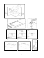
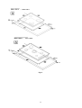
INSTRUCTIONS FOR THE INSTALLATION, MAINTENANCE AND USE OF FIXED HOBS WITH GAS OR MIXED SUPPLY 59X50 cm (TYPE P61/P61V) Model P680 1 PRO X & P680 1 H9 X 86X50 cm (TYPE P91/P91V) Model P910 1 PRO X & P910 1 H9 X READ THE INSTRUCTION BOOKLET BEFORE INSTALLING AND USING THE APPLIANCE. These instructions are valid only for those countries which are indicated by their identification symbol on the front cover of the instruction booklet and on the label on the appliance. The manufacturer cannot be held responsible for any damage to things or persons caused by an incorrect installation or by incorrect use of the appliance. The manufacturer cannot be held responsible for any inaccuracies due to errors in printing or writing contained in this booklet. The appearance of the figures shown is also only approximate. The manufacturer reserves the right to make changes to his products when it is considered necessary and useful without effecting the essential features regarding safety and function. INDEX: TECHNICAL MANUAL FOR THE INSTALLER ........................................................................................................ pag. 2 Inserting the hob ......................................................................................................................................................... pag. 2 Fixing the hob – Advice about installation ................................................................................................................... pag. 3 Ventilation and airing of the premises – Connection to the gas supply ....................................................................... pag. 3 Adaptation to different types of gas ............................................................................................................................ pag. 4 Regulation of the burners ............................................................................................................................................ pag. 4 Connection to the electricity supply ............................................................................................................................. pag. 4 USE AND MAINTENANCE MANUAL ........................................................................................................................ pag. 5 Description of types of hobs ........................................................................................................................................ pag. 5 Use of the burners ....................................................................................................................................................... pag. 5-6 Cleaning of the appliance ............................................................................................................................................ pag. 6 Service & maintenance instructions.............................................................................................................................. pag.6 Figures ........................................................................................................................................................................ pag. 8-11 Electrical Diagran ........................................................................................................................................................ pag. 10 THIS APPLIANCE HAS BEEN DESIGNED FOR NON PROFESSIONAL USE IN HOUSEHOLDS. By ensuring this product is disposed of correctly, you will help prevent potential negative consequences for the environment and human health, which could otherwise be caused by inappropriate waste handling of this product. The symbol on the product indicates that this product may not be treated as household waste. Instead it shall be handed over to the applicable collection point for the recycling of electrical and electronic equipment. Disposal must be carried out in accordance with local environmental regulations for waste disposal. For more detailed information about treatment, recovery and recycling of this product, please contact your local city council office. TECHNICAL MANUAL FOR THE INSTALLER INFORMATION FOR THE INSTALLER The installation, all regulations, changes and maintenance referred to in this part must only be carried out by qualified staff. A wrong installation can cause damage to persons, animals or things which the manufacturer cannot be held responsible for. The safety and automatic regulation devices on the appliances can only ever be changed by the manufacturer or by the supplier which has been authorised to do so. This appliance shall be installed only by authorised persons and in accordance with the manufacturer's installation instructions, local gas fitting regulations, municipal building codes, electrical wiring regulations, local water supply regulations, AS/NZS 5601.1-2010-Gas Installations–General installations and any other statutory regulations. This appliance is not intended to be operated by means of an external timer or separate remote-control system. NOT FOR USE IN MARINE CRAFT, CARAVANS OR MOBILE HOMES UNLESS EACH BURNER IS FITTED WITH FLAME SAFEGUARD. WHERE THIS APPLIANCE IS INSTALLED IN MARINE CRAFT OR IN CARAVANS, IT SHALL NOT BE USED AS A SPACE HEATER. WARNING: SERVICING SHOULD BE CARRIED OUT ONLY BY AUTHORISED PERSONNEL. DO NOT MODIFY THIS APPLIANCE. INSERTING THE HOB When you have removed the various adjustable parts from their internal and external packaging, check that the hob is intact. If you are in doubt do not use the appliance and contact the qualified staff. The parts which make up the packaging ( polystyrene, bags, boxes, nails etc. ), are dangerous objects and must be kept out of children’s reach. Taking into consideration the specific dimensions of the appliance (see table N°1 & Fig. 17), make an opening in the work surface (see figure): Hobs type P61/P61V (59x50 cm) P91/P91V (86x50 cm) with right angle corner Fig. 1. using the measurements indicated in table N°.1 & Fig.17. The appliance must be classified in class 3 and thus it is subject to all the regulations indicated by the norms regarding these appliances. 2 Table N°.1 P6 P9 W (cm) 57 84 D (cm) 48 48 L1 min (cm) L2 min (cm) L3 min (cm) L4 min (cm) 6 4 10 70 FIXING THE HOB In order to prevent liquids from accidentally leaking into the kitchen unit underneath the appliance is equipped with a special seal. To put on this seal follow the instructions below very carefully. 1) Stretch out the seal along the edge of the opening, taking care to overlap the joining points. (fig. 2). 2) Insert the hob into the opening in the kitchen unit. 3) With a screwdriver assemble the 4 plates A with the special screw B (fig. 3). 4) Move the plates along and fix them using screw B. 5) Reinsert the part of the seal on the outside of the hob. Data Label - The Data Label is located on the bottom of the appliance. A duplicate Data Label is supplied to adhere in an accessible area next to the appliance. This appliance is suitable for Natural Gas and Universal LPG; ensure that the available gas supply matches the Data Label and the gas type label. IMPORTANT INFORMATION CONCERNING THE INSTALLATION OF THE APPLIANCE We inform the installer that this hob can be installed by itself, in an isolated position or inserted between two kitchen units or between one kitchen unit and a wall. Furthermore the back wall and surrounding surfaces must resist a temperature of 65 K. To prevent the plastic layer which covers the kitchen unit from ungluing, the glue used to join the two surfaces together must resist temperatures of up to 150 °C The installation of the appliance must be carried out according to the norms in force of the country concerned and the appliance must be installed in a well ventilated place. This appliance is not equipped with devices to remove the products of combustion. The appliance must therefore be connected following the norms for installation mentioned above. Special attention must be paid to the information below regarding aeration and ventilation of the premises. VENTILATION OF THE PREMISES To guarantee that the appliance works correctly it is necessary that the place where the appliance is installed is continuously ventilated. The volume of the premises must not be less than 25 m³ and the quantity of air needed must be based on the regular combustion of gas and on the ventilation of the premises. The natural flow of air will take place through permanent openings made in the wall of the premises to be ventilated: these openings will be connected to the outside and must have a minimum section of 100 cm² ( see Fig. 4 ). These openings must be made in such a way that they cannot be obstructed. POSITION AND VENTILATION The cooking appliances that use gas must always remove the products of combustion via a hood linked to chimneys, chimney flues or via a direct connection to the outside ( see Fig. 5A ). If it is not possible to fit a hood it is possible to use a fan, fitted on the window or facing directly outside, which operates when the appliance is in use. ( see Fig. 5B ). In this way the norms in force of the country concerned regarding the ventilation of premises are strictly followed. WHEN THE APPLIANCE IS INSTALLED SO THAT THE BASE CAN BE TOUCHED, A PROTECTING SHIELD MUST BE FITTED. THIS SHIELD MUST BE AT LEAST 20MM FROM THE LOWEST PART OF THE APPLIANCE AND CAN BE CAPABLE OF WITHSTANDING THE APPLIANCE TEMPERATURES. LOCATION OF CONNECTION POINTS P91 model – The gas inlet connection is located on the underside of the hob. Looking from the front it is located in the top right hand corner 30mm from the right edge and 60mm from the top edge. See figure 6B. The electrical connection exits the terminal block which is mounted on the underside of the hob. It is situated 122mm from the right edge of the hob and 28mm from the top edge. P61 model - The gas inlet connection is located on the underside of the hob. Looking from the front it is located in centre of the base and 60mm from the top edge. See figure 6A. The electrical connection exits the terminal block which is mounted on the underside of the hob. CONNECTING THE APPLIANCE TO THE GAS SUPPLY Before connecting the appliance to the gas supply you first need to remove the plastic protective plug for the gas supply which is inserted under pressure in the gas inlet connection. To remove the plug simply unscrew it. Then make sure that the details shown on the label on the lower part of the case are compatible with those of the gas supply. A label on the last page of this manual and on the lower part of the case indicates the conditions for regulating the appliance: type of gas and pressure used. IMPORTANT: This appliance must be installed in accordance with the norms in force of the country concerned and it must only be used in a well-ventilated place. ATTENTION: Remember that the gas inlet connection for the appliance is threaded 1/2 gas cylindrical male in accordance with the norms UNI-ISO 228-1. (Fig. 16) There are two ways to make the connection to the main gas line: A. The hotplate can be connected with rigid pipe as specified in AS5601 table 3.1. B. The hotplate can be connected with a Flexible Hose, which complies with AS/NZS 1869 (AGA Approved), 10mm ID, class B or D, no more than 1.2m long and in accordance with AS5601. WARNING: Ensure that the hose assembly is restrained from accidental contact with the flue or flue outlet of an underbench oven and it does not contact the hot surfaces of the hotplate, oven, dishwasher or other separate appliance that may be installed underneath or next 3 to the hotplate. The hose should not be subjected to abrasion, kinking or permanent deformation and should be able to be inspected along its entire length. Unions compatible with the hose fittings must be used and connections tested for gas leaks. The supply connection point must be accessible with the appliance installed. Fit the supplied elbow and gasket as shown in Fig.16 The gas inlet connection has a 1/2" BSP male thread. When making the connection, take care not to apply excessive stress by counterbalancing tightening force. Ensure that the available gas supply is the same as the gas type label affixed to the base of the hob. If not, contact Bertazzoni for a Gas Conversion Kit. The gas supply pressure must be adjusted in accordance with the data label for the gas type. Natural Gas The natural gas regulator supplied must be fitted for natural gas. Ensure the arrow on the regulator points towards the direction of the gas flow. The test point pressure must be adjusted to 1.00 kPa with the largest burner operating on maximum flame. U-LPG Fit the Universal LPG test point assembly (supplied in the gas conversion kit). An AGA Approved gas regulator suitable for a supply pressure of 2.75kPa should be part of the gas tank supply. ADAPTING TO DIFFERENT TYPES OF GAS Before carrying out any maintenance work, disconnect the appliance from the gas and electric supply. - CHANGING THE NOZZLES FOR USE WITH OTHER TYPES OF GAS: To change the nozzles of the burners use the following procedure: Lift up the burners and unscrew the nozzles ( Fig. 7) using an adjustable spanner of 7 mm and change the nozzles with those designed for the new gas supply according to the information given in TABLE N° 2 shown below. ATTENTION: After carrying out the changes described above, the technician must put the label corresponding to the new gas supply on the appliance to take the place of the old label. This label is found in the bag containing spare nozzles. TABLE N°2: Adaption to various types of gas Burner Auxiliary Semi-Rapid Rapid Wok (Inner ring) Wok (Inner + Outer ring) Types of Gas NG U-LPG NG U-LPG NG U-LPG NG U-LPG NG Pressure kPa 1.0 2.75 1.0 2.75 1.0 2.75 1.0 2.75 1.0 Nozzle Diameter mm. 0,92 0,56 1,17 0,73 1,55 0,98 0.80 0.50 0.80 (Inner) 1.14 x 2 (Outer) Hourly Gas Consumption (MJ) 4.2 4.0 6,6 6,9 11.5 12.3 3.1 3.1 15.6 (combined) U-LPG 2.75 0.50 (Inner) 0.70 x 2 (Outer) 15.6 (combined) REGULATION OF BURNERS: 1) Regulation of the "MINIMUM" on the burners To regulate the minimum on the burners carry out the following procedure indicated below: 1) Turn on the burner and put the knob onto position MINIMUM ( small flame ). 2) Remove the knob ( Fig. 8) of the tap which is set for standard pressure. The knob is found on the bar of the tap itself. 3) Beside the tap bar on the work top, use a small screwdriver that fits the screw (gold) found on the lower part of the tap (auxiliary, semirapid, rapid Fig. 8) (dual fig.9) and turn the fixing screw to the right or left until the flame of the burner is regulated in the most suitable way to MINIMUM. 4) Make sure that that the flame does not go out when changing the position quickly from MAXIMUM to the MINIMUM position. ATTENTION: The regulation described above can be carried out only with burners using methane gas and city gas ( where available), while with burners using liquid gas the screw must be fully screwed in, in a clockwise direction. CONNECTION OF THE APPLIANCE TO THE ELECTRICITY SUPPLY: Connection to the electricity supply must be carried out according to the norms and indications of the law in force. Before carrying out the connection check that: - The electric charge of the system and the sockets are suitable for the maximum power of the appliance (see label on the lower part of the case). - The socket or system is equipped with an efficient earth connection according to the norms and indications of the law currently in force. No responsibility can be held if these indications are not respected. When the connection to the electricity supply is made with a socket. Fit onto the electric cable a standard plug ( if it is not provided ) which is appropriate for the charge indicated on the label. Connect up the wires according to the diagram in Fig. 10 taking care to respect the corresponding pairs listed below: letter L (phase) = brown coloured wire; letter N (neutral) = blue coloured wire; ” earth = green-yellow coloured wire; symbol” - The electric cable must be positioned so that it cannot reach a temperature of over 75 K at any point. - Do not use reducers, adapters or shunts for the connection as they could cause false contacts and subsequent dangerous overheating. WARNING: The plug must be made accessible after installation for easy servicing and maintenance. 4 WARNING: If the supply cord is damaged, it must be replaced by the manufacturer or its service agent or a similarly qualified person in order to avoid a hazard. When the connection is made directly with the electricity supply: - Make sure that there is a device to disconnect the appliance from the mains with a contact opening distance sufficient for complete disconnection in category III overvoltage conditions. - Place a single-pole switch between the appliance and the electricity supply. The switch must be of a suitable charge for the appliance with a minimum opening between the contacts of 3 mm. - Remember that the earth wire must not be interrupted by the switch. - Alternatively the electrical connection can also be protected by a differential switch of high sensitivity. - You are strongly advised to fix the special yellow-green earth wire to an efficient earthing system BEFORE LEAVING When the installation is complete, always check for gas leaks using a soapy solution. Never use a flame to make this check. Ignite all burners on high flame to ensure correct operation of gas valves, burners and ignition. Turn gas taps to low flame position and observe each burner to ensure they ignite completely at all ports and that the flame is stable. Conduct these checks for each burner individually and concurrently. When satisfied with the hotplate, please instruct the user on the correct method of operation. In case the appliance fails to operate correctly after all checks have been carried out, please call the Bertazzoni Service Centre. USE AND MAINTENANCE MANUAL IMPORTANT SAFETY INSTRUCTIONS DO NOT USE OR STORE FLAMMABLE MATERIALS IN THE APPLIANCE STORAGE DRAWER OR NEAR THIS APPLIANCE. DO NOT SPRAY AEROSOLS IN THE VICINITY OF THIS APPLIANCE WHILE IT IS IN OPERATION. DO NOT STORE OR USE FLAMMABLE LIQUIDS OR ITEMS IN THE VICINITY OF THIS APPLIANCE. DO NOT MODIFY THIS APPLIANCE. WHERE THIS APPLIANCE IS INSTALLED IN MARINE CRAFT OR IN CARAVANS, IT SHALL NOT BE USED AS A SPACE HEATER. WARNING: SERVICING SHOULD BE CARRIED OUT ONLY BY AUTHORISED PERSONNEL. This appliance is not intended for use by persons (including children) with reduced mental or motorial capacities or who have no experience and knowledge unless under supervision or instructed on use of the appliance by a person responsible for their safety. Children must be watched to ensure that they do not play with the appliance DESCRIPTION OF HOBS 1 2 3 4 5 6 GAS HOB TYPE P680, GAS HOB TYPE P910, DESCRIPTIVE CAPTION FOR HOB (Figs. 12 13) Auxiliary burner Semi-rapid burner Rapid burner Dual burner Front left burner knob Front right burner knob see Fig. 12 see Fig. 13 - Electrical Diagram A - Electrical Diagram B CAPTION FOR ELECTRICAL DIAGRAM (Diagrams A B) 1 Electric panel 2 Lighter button 3 Ignition device 4 Lighting plugs L Brown (phase) N Blue (neutral) 7 Back left burner knob 8 Back right burner knob 9 Central burner knob 10 Front central burner knob 11 Back central burner knob ‘ ’ Yellow/Green (earth) USE OF THE BURNERS On the control panel above every knob there is a diagram which indicates which burner the knob in question refers to. The burners can be turned on in several ways according to the type of appliance and its individual features: - Manual “On” switch ( this is always possible even if the electric current is cut off ): Turn the knob corresponding to the selected burner in an anticlockwise direction so that the knob is at MAXIMUM (this corresponds to a large flame) and then put a lit match to the burner. - Electric “On” switch: Turn the knob corresponding to the selected burner in an anticlockwise direction so that the knob is at MAXIMUM (this corresponds to a large flame) and then press the lighter button and let it go as soon as the burner is alight.. 5 - Automatic Electric “On” switch: Turn the knob corresponding to the selected burner in an anticlockwise direction so that the knob is at MAXIMUM (this corresponds to a large flame) and then press in the knob. Let it go as soon as the burner is alight. - “On “ switch for burners with safety device ( thermocouples ): Turn the knob corresponding to the selected burner in an anticlockwise direction so that the knob is at MAXIMUM (this corresponds to a large flame) and then use one of the lighting devices described above. When the burner is lit keep the knob pressed in for about 10 seconds in order to allow the flame to heat up the thermocouple. If the burner goes out when letting the knob go, repeat the operation all over again. Use of the Dual burner (Fig.14) This model controls both the central and the external crown of the burner with just one valve. To ignite the central crown and the external crown of the burner, press and turn the knob to the maximum delivery position 1 and hold it down until ignition; in this position both the internal and the external flame are at maximum. Turn the knob to position 2 to have the external crown at minimum and the internal crown at maximum flame Turn the knob to position 3 to have the internal crown at maximum and the external crown off Turn the knob to position 4 to have the internal crown at minimum and the external crown off. If the flame does not light after the first attempt, wait 5 minutes for the gas to dissipate before attempting to re-light the burner. N.B.: You are advised not to try and light a burner if its flame divider is not correctly in place. Advice for the best use of the burners: - Use suitable pans for each burner ( see tab. n° 4 and Fig. 15). - When boiling point is reached turn the knob on to MINIMUM. - Always use pans with a lid. TABLE N°4: Recommended pan diameters. BURNER PAN DIAMETERS recommended (cm.) Auxiliary 12 - 14 Semi-rapid 14 - 26 Rapid 18 - 26 Dual 22 - 26 ATTENTION: use containers with a flat bottom ATTENTION: If there is no electric current you can light the burners with matches. Lighting the burners with safety thermocouples can only be carried out when the knob is on MAXIMUM (large flame) .When cooking food with oil or fat which can easily set alight, the user must not leave the appliance. Do not use sprays near the appliance when it is in use. When using the burners make sure that the pan handles are in the correct position. Keep children away. If the hob has a lid, before closing it, make sure that the surrounding work surface is cleaned of any food that has been left there. NOTE: The use of a gas cooking appliance produces heat and humidity in the place where it is installed. Therefore you need to ensure that the place is well ventilated, keeping clear the natural ventilation openings (Fig. 4 ) and using the mechanical ventilation device/ flue or electric fan ( Fig. 5A and 5B ). Intensive or prolonged use of the appliance may require additional ventilation such as by opening a window or an increased ventilation efficiency obtained by increasing the power of the mechanical ventilators if it is present. ABNORMAL OPERATION Any of the following are considered to be abnormal operation and may require servicing: • Yellow tipping of the burner flame. • Burners failing to remain alight. • Sooting up of cooking utensils. • Burners extinguished by cupboard doors. • Burners not igniting properly. • Gas valves, which are difficult to turn. In case the appliance fails to operate correctly, contact Bertazzoni. CLEANING OF THE APPLIANCE Before carrying out any cleaning operation disconnect the appliance from the electric mains and turn off the main tap which supplies the appliance with gas. Cleaning the worktop: Periodically the burner heads, enamelled steel grills, enamelled lids and flame dividers must be cleaned with warm soapy water, rinsed and dried well. Any liquid which overflows from the pan must always be removed with a cloth. If opening or closing any tap is difficult do not force it but ask for an urgent check from the technical assistant. Cleaning of the enamelled parts: To maintain the features of the enamelled parts they must be cleaned frequently with soapy water. Never use abrasive powders. Avoid leaving acid or alkaline substances on the enamelled parts (vinegar, lemon juice, salt, tomato juice etc.) and washing the enamelled parts when they are still warm. Cleaning of the stainless steel parts: Clean the parts with soapy water and then dry them with a soft cloth. The shininess is maintained by periodically cleaning with the special products normally available on the market. Never use abrasive powders. Cleaning of the burner flame dividers: as they are not fixed, the flame dividers can be cleaned by simply removing them and cleaning with soapy water. After drying them well and checking that the holes are not blocked, put them back into their correct position. SERVICE & MAINTENANCE INSTRUCTIONS Service and maintenance only to be carried out by an authorised person Routine maintenance Have the condition and efficiency of the gas pipe and the pressure regulator (if installed) checked periodically. If anomalies are found, do not repair components but have the faulty component replaced. To ensure good performance and safety, the gas regulator taps must be greased periodically. Periodic lubrication of the taps and any other appliance service must only be carried out by Authorised Personnel. 6 Changing the parts Before carrying out any maintenance work, disconnect the appliance from the gas and electric supply. To replace different components such as burners, taps and electrical parts you must take out the hob from the kitchen unit by releasing the fixing hooks, unscrew the fixing screws of the burners on the work top, unscrew the fixing nuts of the electric plates which are visible on the lower part of the hob and remove the worktop in order to carry out the replacement of the defective parts. NOTE: If the taps need replacing you also need to unscrew the two fixing screws of the gas ramp at the bottom of the hob which are found on the upper part of the latter. For appliances equipped with automatic “ON” switches you must dismantle the “ON” switch chain before replacing the taps. You are advised to change the seal on the tap every time you replace a tap in order to ensure a perfect hold between the body and ramp. WARNING: The power cord supplied with the appliance is connected to the appliance with a type Y connection (in compliance with standards EN 60335-1, EN 60335-2-6 and subsequent amendments) for which it must be replaced by the manufacturer or its service agent or a similarly qualified person in order to avoid a hazard. In the event of wear or damage to the mains cable, replace it following the indications shown below in table n°3: TABLE N° 3: Types and sections of the electric mains cable for hobs Dimensions of hob Type of hob 59 x 50 cm. 86 x 50 cm. gas burners Type/ section of mains cable H05RR-F 3x0,75 mm2 WARNING: If you replace the electric mains cable the installer must have the earth conductor about 2 cm longer than the phase conductors and must also take heed of the warnings regarding electric connection. Oiling the taps: (This must be carried out by qualified staff from a technical assistance centre) If a tap becomes difficult to move you must oil the tap, without delay, following the instructions given below: 1) Dismantle the main part of the tap by unscrewing the two screws that can be found on the bar of the tap itself. (Fig. 11) 2) Take out and clean the holding cone and its setting with a cloth soaked in diluent. 3) Oil the cone lightly with the special oil. 4) Insert the cone, move it a few times, take it out again, remove the excess oil and make sure that the areas where the gas flows are not obstructed. 5) Reassemble all the pieces in the reverse order to that followed for the dismantling and check that the tap is working properly. After-sales technical service and spare parts Before leaving the factory, this appliance was tested and adjusted by specialist skilled staff to give the best operating results. Any subsequent necessary repairs or adjustments must be carried out with the greatest care and attention by authorised personnel. For this reason, we strongly advise you contact the Bertazzoni Service Center, specifying the nature of the problem, the model of the equipment and the serial number. This data is provided on the data label adhered to the base of the appliance and on the duplicate data label. Always use original Bertazzoni spare parts. BERTAZZONI GROUP ABN 38 069 686 326 650 Bridge Road, Richmond, Victoria 3121 Service & Spare Parts: 1300 748 308 Bertazzoni After Sales Service - P.O. Box 543 SOMERTON VIC 3061 Email: [email protected] 7 Fig.1 Fig.2 Fig.4 Fig.6A Fig.3 Fig.5A Fig.5B Fig.6B Fig.7 8 Fig. 8 Fig. 9 Fig.10 Fig.11 Fig.12 Fig.13 9 Fig.14 Fig.15 Fig.16 10 / P680 1 H9 X / P910 1 H9 X Fig.17 11 Cod. 310693 12