1
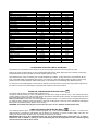
HEIGHT ADJUSTABLE LEGS (Fig.2)
Legs are packed in the top box.
Legs should be installed with the appliance being near the location of final installation, they are not secure for long
transport. After unpacking the range, raise it about a foot to insert the legs in their bases assembled on the lower part of
the cooker and lower the range gently to keep any undue strain from legs and mounting hardware. It is recommended to
use a pallet or lift jack instead of tilting the unit.
BACKGUARD INSTALLATION INSTRUCTION
1)
2)
3)
4)
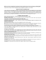
Remove n°2 screws fixing worktop as shown in fig.3
Place front part of the backguard and attach it from bottom side with the two removed screws (point 2) as shown in
fig .4
Fix the front part of the backguard with the screws supplied with the backguard kit (fig.5)
Assemble back part with front part of the backguard and fix them with a screws supplied with the backguard kit
(fig.6)
ANTI-TILTING CHAIN
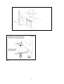
The cooker is supplied with two chains which are connected to the rear left and right of the appliance. The chains should
be connected to the wall directly behind the chains as low as possible to prevent the appliance from tilting forward. If the
appliance is installed between two cupboards, drill a hole on each side of the cupboards, pass the chains through the
holes and anchor the chains within each cupboard. Ensure the chain connections are strong enough to support the
weight of the appliance and taught to prevent it from tilting forward.
WARNING: In order to prevent accidental tipping of the appliance, for example a child climbing onto the open oven door,
the stabilising means must be installed. Ensure the chains are correctly anchored to prevent the appliance from tilting
forward and to prevent strain on the hose when the cooker is pulled forward.
MAKE SURE THE ANTI-TILTING CHAINS ARE TAUGHT WHEN ANCHORED TO PREVENT THE APPLIANCE
TILTING.
APPLIANCE ELECTRIC CONNECTION:
The electric connection must comply with the current legal standards and regulations.
Before making the connection, check that:
- The system electrical rating and the current outlets are adequate for the maximum power output of the appliance (see
the label applied to the bottom of the casing).
- The outlet or the system is equipped with an efficient ground connection in accordance with the current legal standards
and regulations. The company will not be responsible for the non-compliance with these instructions.
When the connection to the power supply network is made using an outlet:
- If the power cord is supplied without a plug, apply a standard plug that is suitable for the load indicated on the label.
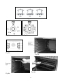
Connect the wires according to the diagram shown in FIG.7 and check that:
letter L (phase) = brown wire;
letter N (neutral) = blue wire;
= green-yellow wire;
ground symbol
- The power cord must be positioned so that an overtemperature of 75 K will not be reached at any point.
- Do not use reductions, adapters or splitters since they might cause false contacts and lead to dangerous overheating.
When the connection is made directly to the electric network:
- Use a device that ensures disconnection from the mains in which the contacts are opened to a distance that permits
complete disconnection according to the conditions for over-voltage category III.
- Remember that the ground wire must not be interrupted by the circuit-breaker.
- As an alternative, the electric connection can also be protected by a high-sensitivity residual current circuit-breaker.
- It is highly recommended to attach the special green-yellow ground wire to an efficient ground system.
WARNING: If the power cord is replaced, the ground wire (yellow-green) connected to the terminal, should be
longer than the other wires by about 2 cm.
WARNING: If the supply cord is damaged, it must be replaced by the manufacturer or its service agent or a
similarly qualified person in order to avoid a hazard.
For New Zealand - This cooking range must be connected to the supply by a supply cord fitted with an appropriately
rated plug that is compatible with the socket-outlet fitted to the final sub-circuit in the fixed wiring that is intended to
supply this cooking range.
TYPES OF POWER CORDS
The appliance is equipped with a terminal for the electric connection placed behind, which is accessible removing the
posterior casing (Fig.8)
The cable of alimentation can be :
Operation at 220-240V~ : use a H05BB-F three-wire cable (cable 3x4 mm²)
Operation at 380-415V2N~ : use a H05RR-F o H07RN-F four-wire cable (cable 4x4 mm²)
3