1
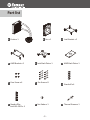
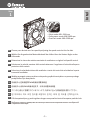
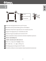
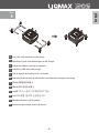
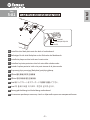
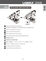
ELC-LM120S-TAA
ELC-LM120S-HP
2 Years Warranty
Index
Limited Warranty
1
Specification
2
Part list
3
Intel Installation
4
AMD Installation
17
Limited Warranty
Please read this limited warranty carefully. Warranty is subject to void under following
criteria:
1. The serial number label or warranty seal is defaced, modified, or removed.
2. Taking apart of the product and/or modification of any component or cable without
ENERMAX’s written authorization.
3. Ignoring connector’s faulty-insertion-prevention design by attaching a connector to a
device under incorrect orientation.
4. Damage caused by natural phenomena or uncontrollable forces, such as lightning,
flooding, fire, earthquake, or misuse, abuse, negligence, accident, wear and tear,
mishandling, misapplication.
This ENERMAX Technology Corporation product is warranted to be free from defects in
material and workmanship for a period of two (2) years from the date of purchase. ENERMAX
Technology Corporation agrees to repair or replace the product, at its own option and at no
charge, if, during the warranty period, it is returned to nearest ENERMAX Technology Corporation subsidiary/agent with all shipping charges prepaid and if inspection reveals that the
product is defective. Please present the proof of purchase for requesting RMA. Charges for
removing or installing the product are excluded under the terms of this warranty agreement.
This warranty shall not apply to any product, which has been subject to connection to a faulty
power source, alteration, negligence, or accident, or to any product, which has been installed
other than in accordance with these instructions. In no event shall ENERMAX Technology
Corporation, or its subsidiaries, or agents be liable for damages for a breach of warranty in an
amount exceeding the purchase price of this product.
If you are uncertain whether or not your ENERMAX liquid cooler is defective, please contact
your dealer/reseller for support!
Web Site: http://www.enermax.com
E-mail: [email protected]
ENERMAX Technology Corporation, 15F-2, No. 888, Jing-Guo Road, Taoyuan City (330),
Taiwan (R.O.C.), Tel. +886-3-316-1675, Fax. +886-3-346-6640
©2013 ENERMAX Technology Corporation. All rights reserved. Specifications are subject to
change without prior notice. Actual product and accessories may differ from illustrations.
Omissions and printing errors excepted. Content of delivery might differ in different countries
or areas. Some trademarks may be claimed as the property of others. Reproduction in any
manner without the written permission of ENERMAX is strictly forbidden.
-1-
Specification
Model
Cold Plate
Pump
Radiator
Tube
ELC-LM120S-HP
ELC-LM120S-TAA
Material
Copper
Bearing
Ceramic Bearing
MTBF
50,000 hrs
Motor Speed
2300 rpm
Rated Voltage
12V
Rated Current
0.3A
Dimension
156 x 120 x 32 mm
Material
Aluminium
Material
FEP
Length
310 mm
505 g
Weight (w/o fan)
Bracket
Fan
Compatibility
Intel® LGA 775/1150/1155/1156/1366/2011
AMD® AM2/AM2+/AM3/AM3+/FM1/FM2
Dimension
120 x 120 x 25 mm
Bearing
Twister Bearing
MTBF
100,000 hrs
Speed
600-1300/2000/2500 rpm
Rated Voltage
Rated Current
12V
0.13A/0.27A/0.45A
0.13A/0.27A/0.45A
Air Flow
28.6~60.3/88.9/111.0 CFM
48.5~102.4/150.9/188.7 m3/h
24.5~51.6/84.6/105.7 CFM
41.6~87.7/143.7/179.7 m3/h
Static Pressure
0.8~1.7/4.7/7.4 mm-H2O
0.8~1.5/2.4/3.7 mm-H2O
Noise Level
15~21.5/27/30 dBA
14~20/27/30 dBA
LED
N/A
12x Blue LED
Connector
4 pin PWM
-2-
Part list
A Cooler x 1
B Fan x 1
D AMD Bracket x 2
E Intel Back Plate x 1
G Case Screw x 4
H Fan Screw x 8
J Stand-off for
Intel LGA 2011 x 4
K Nut Setter x 1
-3-
C Intel Bracket x 2
F AMD Back Plate x 1
I Stand-off x 4
L Thermal Grease x 1
Intel Installation
-4-
Step
Intel
1
– Silent mode: 600~1300 rpm
– Performance mode: 600~2000 rpm
– OverClock mode: 600~2500 rpm
EN Choose your desired max. fan speed by adjusting the speed control at the fan hub.
DE Wählen Sie die gewünschte Maximaldrehzahl des Lüfters über den kleinen Regler an der
Lüfternabe.
FR Déterminez la vitesse de rotation maximale du ventilateur en réglant le dispositif central.
IT Selezionare la velocità massima della ventola attraverso il regolatore di velocità nella parte
posteriore della ventola
ES Seleccione la velocidad máxima del ventilador a través del control de velocidad en la parte
trasera del ventilador
PL Według wymagań systemu wybierz maksymalną prędkość wentylatora za pomocą małego
przełącznika z tyłu wentylatora.
TN 於扇框中心控制鈕選擇PWM風扇所需最高轉速
CN 在扇框中心设有PWM风扇调速开关,可自由调整风扇转速
JP ファン中心部分に搭載されているスイッチで、お好みに合った回転範囲を選択して下さい。
KR 팬 허브에서 속도 조정 장치를 조절하여 원하는 최대 팬 속도를 선택하십시오.
ID Pilih kecepatan kipas yg anda inginkan dengan menyesuaikan kontrol kecepatan pada fan hub.
RU Выберите скорость вращения вентилятора маленьким переключателем на обратной
стороне вентилятора.
-5-
Step
Intel
2
EN Attach the fan and the radiator to the chassis
DE Schrauben Sie den Lüfter und den Radiator am Gehäuse fest.
FR Fixez le ventilateur et le radiateur sur le châssis
IT Fissare la ventola e il radiatore al case
ES Fijar el ventilador y el radiador a la caja
PL Zamontuj wentylator i radiator na obudowie komputerowej.
TN 安裝風扇及散熱排於機殼
CN 将风扇以及散热排安装在机箱上
JP ファンをラジエーターに設置してケースに取り付けて下さい。
KR 팬과 방열기를 PC 케이스에 부착하십시오.
ID Pasang kipas dan radiator ke casing
RU Закрепите вентилятор и радиатор на корпусе.
-6-
Step
Intel
3
LGA775
LGA1150/1155/1156
LGA1366/2011
EN Please select the appropriate hole for your CPU socket.
DE Bitte wählen Sie die passende Bohrung für Ihre CPU-Plattform
FR Sélectionnez l'emplacement approprié pour votre socket de votre CPU
IT Scegliere il foro appropriato per il socket della vostra CPU.
ES Seleccione el agujero apropiado para el socket de la CPU.
PL Wybierz odpowiednie otwóry montażowe w zależności od platformu procesora.
TN 依系統CPU腳位選擇適合孔位
CN 可依据CPU安装位置 选择与其相对应的孔位
JP CPUのソケットに合ったネジ穴を使用して下さい。
KR CPU 소켓에 맞는 나사 홀을 선택하십시오.
ID Pilih lubang yang sesuai dengan socket CPU anda
RU Пожалуйста, выберите соответствующие отверстия для вашего процессора.
-7-
Step
Intel
4
EN Insert the Intel brackets into the pump
DE Montieren Sie die Intel-Halterungen an der Pumpe.
FR Insérez les supports Intel dans la pompe
IT Inserire le staffe Intel nella pompa
ES Fijar el soporte de montaje Intel a la bomba
PL Zamontuj przeznaczone do procesorów Intel wsporniki mocujące na pompę.
TN 將Intel支架固定於水泵上
CN 将intel支架 固定在水泵上
JP Intel用ブラケットをポンプに取り付けて下さい。
KR Intel 브라켓을 펌프에 삽입하십시오.
ID Masukkan bracket intel ke pompa
RU Закрепите крепление «Intel» на насосе.
-8-
5-A1
*LGA775/1150/1155/1156/1366
LGA1366
LGA1150/1155/1156
LGA775
EN Install the Intel back plate onto the back of motherboard.
DE Befestigen Sie die Intel-Backplate an der Rückseite des Mainboards.
FR Installez la plaque arrière Intel sous la carte-mère
IT Installare la piastra posteriore Intel sul retro della scheda madre.
ES Instalar la placa posterior Intel en la parte trasera de la placa madre
PL Przymocuj płytę mocującą (Backplate) pod płytą główną.
TN 將Intel強化背板安裝於主板背面
CN 将Intel 强化背板安装在主板背面
JP Intel 用バックプレートをマザーボードの裏側に設置して下さい。
KR Intel 백 플레이트를 마더보드 후면에 설치하십시오.
ID Pasang plat belakang intel ke belakang motherboard
RU Установите крепёжную пластину «Intel» к обратной стороне на материнской плате.
-9-
Intel
Step
5-A2
*LGA775/1150/1155/1156/1366
Nut Setter
EN Tighten the stand-off to the motherboard
DE Schrauben Sie die Backplate mit den Abstandshaltern am Mainboard fest.
FR Serrez la vis du support à la carte-mère
IT Fissare i montanti alla scheda madre
ES Fijar los tornillos de pilar a la placa madre
PL Przykręć płytę mocującą za pomocą nakrętek dystansowych.
TN 將銅柱固定於主板上
CN 将铜柱固定在主板的相应位置上
JP 専用ネジを使用して、バックプレートをマザーボードに固定してください。
KR 마더보드 지지대를 마더보드에 고정하십시오.
ID Kencangkan stand off ke motherboard
RU Затяните гайки на материнской плате.
- 10 -
Intel
Step
Step
Intel
5-B
*LGA2011
Nut Setter
EN Tighten the Intel LGA 2011 stand-off to the motherboard
*Intel LGA 2011 socket does not require the back plate.
DE Schrauben Sie die Backplate mit den passenden LGA2011-Abstandshaltern am Mainboard fest.
*Die Montage für den Intel-LGA-2011-Sockel bedarf keiner Back-Plate
FR Serrez la vis du support Intel LGA2011 à la carte-mère
*socket Intel LGA2011 n’a pas besoin de plaque arrière
IT Fissare i montanti per Intel LGA 2011 alla scheda madre
*Il socket Intel LGA 2011 non ha bisogno della piastra posteriore
ES Fije los tornillos de pilar para Intel LGA 2011 a la placa madre
*El zócalo Intel LGA 2011 no necesita la placa posterior
PL Przykręć płytę mocującą za pomocą przeznaczonych do platformy LGA2011 nakrętek dystansowych.
*gniazdo platformy Intel LGA 2011 nie wymaga tylnej płyty
TN 將LGA2011銅柱固定於主板上
*安裝Intel LGA 2011不需背板
CN 将LGA2011铜柱固定在主板的相应位置上
*安装Intel LGA 2011不需背板
JP Intel LGA 2011の場合、2011専用ネジを使用しバックプレートをマザーボードに固定して下さい。
*Intel LGA 2011の取り付けにはバックプレートを使用しないため
KR Intel LGA 2011 지지대를 마더보드에 고정하십시오.
*Intel LGA 2011은 백 플레이트가 필요 없으며
ID Kencangkan Intel LGA 2011 stand off ke motherboard
*Soket Intel LGA 2011 Tidak memerlukan penutup bagian belakang
RU Затяните гайки «Intel LGA 2011» на материнской плате.
*Intel LGA 2011 не нуждается в крепёжной пластине. Пожалуйста
- 11 -
Step
Intel
6
EN Apply the thermal grease evenly on the CPU surface
DE Verteilen Sie gleichmäßig eine dünne Schicht Wärmeleitpaste auf der CPU-Oberfläche.
FR Appliquez une couche uniforme de pâte thermique sur la surface du CPU
IT Applicare in modo uniforme la pasta termica sulla superficie della CPU
ES Aplicar de forma uniforme la pasta térmica en la superficie de la CPU
PL Nałóź równomiernie cienką warstwę pasty termoprzewodzącej na metalową osłonę
na procesorze.
TN 將散熱膏均勻的塗抹於CPU表面
CN 请在CPU表面均与涂抹散热硅脂
JP サーマルグリスをCPUの表面に均一になるよう薄く塗って下さい。
KR CPU 표면에 구리스를 평평히 펴 바르십시오.
ID Oleskan secara merata thermal pasta ke permukaan CPU
RU Нанесите термопасту равномерно на поверхность процессора.
- 12 -
Step
Intel
7
EN Remove the protect film from the cold-plate
DE Entfernen Sie die Schutzfolie von der Kühlplatte der Pumpe.
FR Retirez le film protecteur de la plaque-froide
IT Rimuovere la pellicola di protezione dalla piastra di raffreddamento
ES Quite la película de protección del bloque de refrigeración
PL Zdjąć folię ochronną z bloku wodnego.
TN 取下水冷頭保護貼膜
CN 使用时请将水冷头保护贴膜取下
JP コールドプレートの保護フィルムを外して下さい。
KR 콜드 플레이트의 보호 필름을 제거하십시오.
ID Lepaskan pita pelindung dari plat pendingin
RU Пожалуйста, удалите защитную крышку с охлаждающей пластины
- 13 -
Step
Intel
8
EN Place the pump on the CPU and tighten the spring screws until all four corners are secured
DE Platzieren Sie die Pumpe auf der CPU und drehen Sie die Federschrauben fest bis alle vier
Seiten fixiert sind.
FR Placez la pompe sur le CPU et serrez les vis à ressort jusqu'à ce que les quatre coins soient
bien fixés
IT Posizionare la pompa sulla CPU e fissare le viti fino a che tutti e quattro gli angoli siano fissati.
ES Coloque la bomba en la CPU y apriete los tornillos hasta que las cuatro esquinas estén fijadas.
PL Umieść pompę na procesorze i przykręć wszystkie cztery srubki sprężyste.
TN 將水泵至於CPU上並鎖緊四邊彈簧螺絲
CN 将水泵置于CPU上并确认四边的弹簧螺丝拧紧
JP 専用ネジを使用して水冷ポンプをCPUの上に固定して下さい。
KR CPU 에 펌프를 놓고 펌프의 네 코너가 단단히 고정 될 때까지 스프링 나사를
고정하십시오.
ID Tempatkan pompa pada CPU dan kencangkan keempat sekrup sampai keempat sudut aman
RU Установите насос на процессоре и затяните все 4 гайки.
- 14 -
Step
Intel
9
Pump
Pump
or
4 pin
EN Connect the pump power connector to the motherboard
DE Schließen Sie den Stromstecker der Pumpe am Mainboard an.
FR Branchez le connecteur d'alimentation de la pompe à la carte-mère
IT Collegare il connettore di alimentazione della pompa alla scheda madre
ES Conecte el cable de la bomba a la placa madre
PL Podłącz wtyczkę do zasilania pompy do plyty głównej.
TN 連接水泵電源於主板
CN 请将水泵电源与主板相应供电口连接
JP 水冷ポンプのコネクターをマザーボードに接続して下さい。
KR 펌프 전원 커넥터를 마더보드에 연결하십시오.
ID Hubungkan konektor daya pompa ke motherboard
RU Пожалуйста, подключите разъем питания насоса к материнской плате.
- 15 -
3 pin
Step
Intel
10
Fan
4 pin
EN Connect the fan connector to the motherboard
DE Schließen Sie den 4-Pin-PWM-Stecker des Lüfters am Mainboard an.
FR Branchez le connecteur du ventilateur à la carte-mère
IT Collegare il connettore della ventola alla scheda madre
ES Conecte el conector del ventilador a la placa madre
PL Podłącz wtyczkę 4-pin PWM wentylatora do płyty głównej.
TN 連接風扇電源於主板
CN 请将风扇电源与主板上的相应供电口连接
JP ファンコネクターをマザーボードに接続して下さい。
KR 팬 커넥터를 마더보드에 연결하십시오.
ID Hubungkan konektor kipas ke motherboard
RU Пожалуйста, подключите разъем вентилятора к материнской плате.
- 16 -
AMD Installation
- 17 -
Step
– Silent mode: 600~1300 rpm
– Performance mode: 600~2000 rpm
– OverClock mode: 600~2500 rpm
EN Choose your desired max. fan speed by adjusting the speed control at the fan hub.
DE Wählen Sie die gewünschte Maximaldrehzahl des Lüfters über den kleinen Regler an der
Lüfternabe.
FR Déterminez la vitesse de rotation maximale du ventilateur en réglant le dispositif central.
IT Selezionare la velocità massima della ventola attraverso il regolatore di velocità nella parte
posteriore della ventola
ES Seleccione la velocidad máxima del ventilador a través del control de velocidad en la parte
trasera del ventilador
PL Według wymagań systemu wybierz maksymalną prędkość wentylatora za pomocą małego
przełącznika z tyłu wentylatora.
TN 於扇框中心控制鈕選擇PWM風扇所需最高轉速
CN 在扇框中心设有PWM风扇调速开关,可自由调整风扇转速
JP ファン中心部分に搭載されているスイッチで、お好みに合った回転範囲を選択して下さい。
KR 팬 허브에서 속도 조정 장치를 조절하여 원하는 최대 팬 속도를 선택하십시오.
ID Pilih kecepatan kipas yg anda inginkan dengan menyesuaikan kontrol kecepatan pada fan hub.
RU Выберите скорость вращения вентилятора маленьким переключателем на обратной
стороне вентилятора.
- 18 -
AMD
1
Step
AMD
2
EN Attach the fan and the radiator to the chassis
DE Schrauben Sie den Lüfter und den Radiator am Gehäuse fest.
FR Fixez le ventilateur et le radiateur sur le châssis
IT Fissare la ventola e il radiatore al case
ES Fijar el ventilador y el radiador a la caja
PL Zamontuj wentylator i radiator na obudowie komputerowej.
TN 安裝風扇及散熱排於機殼
CN 将风扇以及散热排安装在机箱上
JP ファンをラジエーターに設置してケースに取り付けて下さい。
KR 팬과 방열기를 PC 케이스에 부착하십시오.
ID Pasang kipas dan radiator ke casing
RU Закрепите вентилятор и радиатор на корпусе.
- 19 -
Step
AMD
3
EN Insert the AMD brackets into the pump
DE Montieren Sie die AMD-Halterungen an der Pumpe.
FR Insérez les supports AMD dans la pompe
IT Inserire le staffe AMD nella pompa
ES Fijar el soporte de montaje AMD a la bomba
PL Zamontuj przeznaczone do procesorów AMD wsporniki mocujące na pompę.
TN 將AMD支架固定於水泵上
CN 将AMD支架固定在水泵上
JP AMD用ブラケットをポンプに取り付けて下さい。
KR AMD 브라켓을 펌프에 삽입하십시오.
ID Masukkan bracket AMD ke pompa
RU Закрепите крепление «AMD» на насосе.
- 20 -
Step
AMD
4
EN Install the AMD back plate onto the back of motherboard.
DE Befestigen Sie die AMD-Backplate an der Rückseite des Mainboards.
FR Installez la plaque arrière AMD sous la carte-mère
IT Installare la piastra posteriore AMD sul retro della scheda madre.
ES Instalar la placa posterior AMD en la parte trasera de la placa madre
PL Przymocuj płytę mocującą (Backplate) pod płytą główną.
TN 將AMD強化背板安裝於主板背面
CN 将AMD强化背板安装在主板背面
JP AMD用バックプレートをマザーボードの裏側に設置して下さい。
KR AMD 백 플레이트를 마더보드 후면에 설치하십시오.
ID Pasang plat belakang AMD ke belakang motherboard
RU Установите крепёжную пластину «AMD» к обратной стороне на материнской плате.
- 21 -
Step
AMD
5
EN Apply the thermal grease evenly on the CPU surface
DE Verteilen Sie gleichmäßig eine dünne Schicht Wärmeleitpaste auf der CPU-Oberfläche.
FR Appliquez une couche uniforme de pâte thermique sur la surface du CPU
IT Applicare in modo uniforme la pasta termica sulla superficie della CPU
ES Aplicar de forma uniforme la pasta térmica en la superficie de la CPU
PL Nałóź równomiernie cienką warstwę pasty termoprzewodzącej na metalową osłonę
na procesorze.
TN 將散熱膏均勻的塗抹於CPU表面
CN 请在CPU表面均与涂抹散热硅脂
JP サーマルグリスをCPUの表面に均一になるよう薄く塗って下さい。
KR CPU 표면에 구리스를 평평히 펴 바르십시오.
ID Oleskan secara merata thermal pasta ke permukaan CPU
RU Нанесите термопасту равномерно на поверхность процессора.
- 22 -
Step
AMD
6
EN Remove the protect film from the cold-plate
DE Entfernen Sie die Schutzfolie von der Kühlplatte der Pumpe.
FR Retirez le film protecteur de la plaque-froide
IT Rimuovere la pellicola di protezione dalla piastra di raffreddamento
ES Quite la película de protección del bloque de refrigeración
PL Zdjąć folię ochronną z bloku wodnego.
TN 取下水冷頭保護貼膜
CN 使用时请将水冷头保护贴膜取下
JP コールドプレートの保護フィルムを外して下さい。
KR 콜드 플레이트의 보호 필름을 제거하십시오.
ID Lepaskan pita pelindung dari plat pendingin
RU Пожалуйста, удалите защитную крышку с охлаждающей пластины
- 23 -
Step
AMD
7
EN Place the pump on the CPU and tighten the spring screws until all four corners are secured
DE Platzieren Sie die Pumpe auf der CPU und drehen Sie die Federschrauben fest bis alle vier
Seiten fixiert sind.
FR Placez la pompe sur le CPU et serrez les vis à ressort jusqu'à ce que les quatre coins soient
bien fixés
IT Posizionare la pompa sulla CPU e fissare le viti fino a che tutti e quattro gli angoli siano fissati.
ES Coloque la bomba en la CPU y apriete los tornillos hasta que las cuatro esquinas estén fijadas.
PL Umieść pompę na procesorze i przykręć wszystkie cztery srubki sprężyste.
TN 將水泵至於CPU上並鎖緊四邊彈簧螺絲
CN 将水泵置于CPU上并确认四边的弹簧螺丝拧紧
JP 専用ネジを使用して水冷ポンプをCPUの上に固定して下さい。
KR CPU 에 펌프를 놓고 펌프의 네 코너가 단단히 고정 될 때까지 스프링 나사를
고정하십시오.
ID Tempatkan pompa pada CPU dan kencangkan keempat sekrup sampai keempat sudut aman
RU Установите насос на процессоре и затяните все 4 гайки.
- 24 -
Step
Pump
Pump
or
4 pin
EN Connect the pump power connector to the motherboard
DE Schließen Sie den Stromstecker der Pumpe am Mainboard an.
FR Branchez le connecteur d'alimentation de la pompe à la carte-mère
IT Collegare il connettore di alimentazione della pompa alla scheda madre
ES Conecte el cable de la bomba a la placa madre
PL Podłącz wtyczkę do zasilania pompy do plyty głównej.
TN 連接水泵電源於主板
CN 请将水泵电源与主板相应供电口连接
JP 水冷ポンプのコネクターをマザーボードに接続して下さい。
KR 펌프 전원 커넥터를 마더보드에 연결하십시오.
ID Hubungkan konektor daya pompa ke motherboard
RU Пожалуйста, подключите разъем питания насоса к материнской плате.
- 25 -
3 pin
AMD
8
Step
AMD
9
Fan
4 pin
EN Connect the fan connector to the motherboard
DE Schließen Sie den 4-Pin-PWM-Stecker des Lüfters am Mainboard an.
FR Branchez le connecteur du ventilateur à la carte-mère
IT Collegare il connettore della ventola alla scheda madre
ES Conecte el conector del ventilador a la placa madre
PL Podłącz wtyczkę 4-pin PWM wentylatora do płyty głównej.
TN 連接風扇電源於主板
CN 请将风扇电源与主板上的相应供电口连接
JP ファンコネクターをマザーボードに接続して下さい。
KR 팬 커넥터를 마더보드에 연결하십시오.
ID Hubungkan konektor kipas ke motherboard
RU Пожалуйста, подключите разъем вентилятора к материнской плате.
- 26 -
ELC-LM120S-TAA
ELC-LM120S-HP
© 2013 Enermax Technology Corporation. All rights reserved. Technical changes, printing errors and mistakes excepted.