1
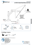
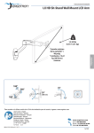
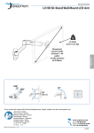
ASSEMBLY INSTRUCTIONS
LX HD Sit-Stand Desk Mount LCD Arm
14-30 lbs
(6.35-13.61 kg)
Maximum Screen
Size* = 46”
*Limited to 30 lbs
maximum
ENGLISH
0.78"-2.56"
(20-65mm)
0.78”-2.25” (20-57mm)
0.5"-2.5" (13-64mm)
360°
70°
360°
20"
(508 mm)
180°
5°
Tools Needed
1/4"
For the latest User Installation Guide please visit: www.ergotron.com
User's Guide - English
Guía del usuario - Español
Manuel de l’utilisateur - Français
Gebruikersgids - Deutsch
Benutzerhandbuch - Nederlands
Guida per l’utente - Italiano
Användarhandbok - svenska
ユーザーガイド : 日本語
用户指南 : 汉语
888-45-311-W-01 rev.E • 11/13
1 of 14
Safety
CAUTION: DO NOT rotate monitor past rear edge of desk. Doing so will create an unstable
situation and may cause equipment damage or personal injury.
ENGLISH
Important! You will need to adjust this product after installation is complete. Make sure all your equipment is properly
installed on the product before attempting adjustments. This product should move smoothly and easily through the
full range of motion and stay where you set it. If movements are too easy or difficult or if product does not stay in
desired positions, follow the adjustment instructions to create smooth and easy movements. Depending on your
product and the adjustment, it may take many turns to notice a difference. Any time equipment is added or removed
from this product, resulting in a change in the weight of the mounted load, you should repeat these adjustment steps
to ensure safe and optimum operation.
888-45-311-W-01 rev.E • 11/13
2 of 14
Components
A
B
C
D
4x
1x
1x
1
4x
M5 x 7mm
1x
1x
2
2.5mm
4x
1x
M4 x 10mm
3
1x
4x
1x
M4 x 10mm
ENGLISH
1x
1x
M3 x 6mm
4
2x
1x 1x
1x
1x
M6
1x
1x
5
8mm
M6 x 45mm
1/4”
5mm
4x
4x
4mm
M5x20mm
4x
6
4x
2x
M4x12mm
M5x12mm
M8 M5 Kit
4x
M6x12mm
M8-M5
Reducer
888-45-311-W-01 rev.E • 11/13
3 of 14
1
CLAMP
GROMMET HOLE
DESK THICKNESS
a
0.78"-1.38" (20-35mm)
1.18"-2.56" (30-65mm)
4mm
ENGLISH
4mm
b
4mm
8mm
1/4”
1/4"
c
4mm
1x
1x
d
1x
1x
CAUTION: Bolt must be
centered in hole.
888-45-311-W-01 rev.E • 11/13
4 of 14
2
Portrait / Landscape Options
OPTION i
If you want full portrait/landscape rotation, skip to step 8 on the next page.
OPTION ii
If you do not want your TV/Monitor to rotate all all, you can stop rotation by inseting
the set screw.
i
ii
ENGLISH
0˚
M3 x 6mm
888-45-311-W-01 rev.E • 11/13
5 of 14
3
Check size of
TV/Monitor hole
pattern
TV/Monitor Hole
Pattern Sizes
VESA Adapter
Configurations
100mm (3-15/16”)
75mm (2-15/16”)
75x75mm
100x100mm
100mm (3-15/16”)
75mm (2-15/16”)
A
100mm (3-15/16”)
7
ENGLISH
200mm (7-7/8”)
B
100x200mm
8
200mm (7-7/8”)
200x200mm
200mm (7-7/8”)
C
8
200mm (7-7/8”)
200x100mm
100mm (3-15/16”)
D
8
888-45-311-W-01 rev.E • 11/13
6 of 14
3
Mount Type A TV/Monitor to Arm
A
75x75mm
100x100mm
4x
M4 x 10mm
100mm (3-15/16”)
75mm (2-15/16”)
M4 x 10mm
100mm (3-15/16”)
75mm (2-15/16”)
ENGLISH
OR
M4 x 10mm
4
10
888-45-311-W-01 rev.E • 11/13
7 of 14
3
Mount VESA Adapters to Arm based on TV/Monitor hole
pattern size (B, C, or D) .
ENGLISH
B
C
D
4x
M5 x 7mm
888-45-311-W-01 rev.E • 11/13
8 of 14
3
Mount Type B, C, or D TV/Monitor to Arm
C
B
D
100mm (3-15/16”)
200mm (7-7/8”)
200mm (7-7/8”)
100mm (3-15/16”)
200mm (7-7/8”)
200mm (7-7/8”)
M5x12mm
NOTE: To reduce M8
holes for use with M5
screws, or if you have a
model with Samsung
holder rings, follow the
M8M5 KIT instructions
on the next page.
OR
10
OR
M4x12mm
M5x12mm
M6x12mm
4
10
888-45-311-W-01 rev.E • 11/13
9 of 14
ENGLISH
M6x12mm
M4x12mm
M8M5 KIT Instructions
NOTE: follow this step only if your TV/monitor has M8 holes which need to be reduced
to M5 or for Samsung models using the holder ring.
Install M8M5 reducer bushing to TV/Monitor and use M5 x 20 mm
monitor screws to secure when using the Samsung holder ring.
TV/Monitor Mounting
M8 size hole
M5 x 20mm
Monitor Screw
M8M5 Reducer Bushing
ENGLISH
Holder Ring
(Not included *Samsung Only)
4
a
2x
Mount extension and arm to pole.
b
c
1x 1x
d
1x
M6
4mm
M6 x 45mm
888-45-311-W-01 rev.E • 11/13
10 of 14
5
Organize and route cables
1x
a
1x
ENGLISH
b
c
888-45-311-W-01 rev.E • 11/13
11 of 14
Adjustment Step
Important! You will need to adjust this product after installation is complete. Make sure all your equipment is
properly installed on the product before attempting adjustments. This product should move smoothly and easily
through the full range of motion and stay where you set it. If movements are too easy or difficult or if product
does not stay in desired positions, follow the adjustment instructions to create smooth and easy movements.
Depending on your product and the adjustment, it may take many turns to notice a difference. Any time
equipment is added or removed from this product, resulting in a change in the weight of the mounted load, you
should repeat these adjustment steps to ensure safe and optimum operation.
To adjust the arm lift:
ENGLISH
6
5mm
CAUTION: DO NOT overtighten fasteners.
Overtightening may cause damage to your
equipment.
WARNING
Increase Lift Strength
5mm
WARNING
If the mounted weight is too heavy or
this product does not stay up when
raised, then you'll need to increase
Lift Strength:
Decrease Lift Strength
If the mounted weight is too light or
this product does not stay down when
lowered, then you'll need to decrease
Lift Strength:
WARNING! Stored Energy Hazard: The arm mechanism is under tension and will move up rapidly, on its own, as
soon as attached equipment is removed. For this reason, DO NOT remove equipment unless the arm has been
moved to the highest position! Failure to follow this instruction may result in serious personal injury and/or
equipment damage!
888-45-311-W-01 rev.E • 11/13
12 of 14
7
To adjust the TV/monitor tilt:
4mm
CAUTION: DO NOT remove screw. Removing
screw may cause damage to equipment.
Increase Friction
Decrease Friction
If this product is too difficult to move
from side-to-side, then you'll need to
decrease friction:
8
To adjust height on pole:
2.5mm
888-45-311-W-01 rev.E • 11/13
13 of 14
ENGLISH
If this product moves too easily from
side-to-side, then you'll need to
increase friction:
4mm
Set Your Workstation to Work For YOU!
Learn more about ergonomic computer use at:
www.computingcomfort.org
Height Position top of screen slightly below eye level.
Position keyboard at about elbow height with wrists flat.
Distance Position screen an arm's length from face—at least 20” (508mm).
Position keyboard close enough to create a 90˚ angle in elbow.
Angle Tilt screen to eliminate glare.
Tilt the keyboard back 10° so that your wrists remain flat.
ENGLISH
To Reduce Fatigue
Breathe - Breathe deeply through your nose.
Blink - Blink often to avoid dry eyes.
Break • 2 to 3 minutes every 20 minutes
• 15 to 20 minutes every 2 hours.
For local customer care phone numbers visit: http://contact.ergotron.com
888-45-311-W-01 rev.E • 11/13
14 of 14