1
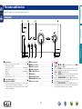
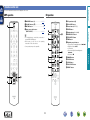
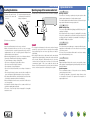
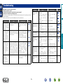
Preparations
Operations
PMA-2020AE
INTEGRATED AMPLIFIER
Information
Owner’s Manual
nSAFETY PRECAUTIONS
CAUTION:
TO REDUCE THE RISK OF ELECTRIC SHOCK, DO NOT REMOVE
COVER (OR BACK). NO USER-SERVICEABLE PARTS INSIDE.
REFER SERVICING TO QUALIFIED SERVICE PERSONNEL.
The exclamation point within an equilateral triangle is intended
to alert the user to the presence of important operating
and maintenance (servicing) instructions in the literature
accompanying the appliance.
WARNING:
TO REDUCE THE RISK OF FIRE OR ELECTRIC SHOCK, DO NOT
EXPOSE THIS APPLIANCE TO RAIN OR MOISTURE.
HOT SURFACE. DO NOT TOUCH.
Hot
surface
mark
The top surface over the internal heat sink may become hot
when operating this product continuously.
Do not touch hot areas, especially around the “Hot surface
mark” and the top panel.
13.Refer all servicing to qualified service personnel.
Servicing is required when the apparatus has been damaged in any way,
such as power-supply cord or plug is damaged, liquid has been spilled or
objects have fallen into the apparatus, the apparatus has been exposed to
rain or moisture, does not operate normally, or has been dropped.
14.Batteries shall not be exposed to excessive heat such as sunshine, fire or
the like.
CAUTION:
To completely disconnect this product from the mains, disconnect the plug
from the wall socket outlet.
The mains plug is used to completely interrupt the power supply to the unit
and must be within easy access by the user.
I
DENON EUROPE
Division of D&M Germany GmbH
An der Kleinbahn 18, Nettetal,
D-41334 Germany
A NOTE ABOUT RECYCLING:
This product’s packaging materials are recyclable and can
be reused. Please dispose of any materials in accordance
with the local recycling regulations.
When discarding the unit, comply with local rules or
regulations.
Batteries should never be thrown away or incinerated
but disposed of in accordance with the local regulations
concerning battery disposal.
This product and the supplied accessories, excluding the
batteries, constitute the applicable product according to the
WEEE directive.
Information
CAUTION:
Read these instructions.
Keep these instructions.
Heed all warnings.
Follow all instructions.
Do not use this apparatus near water.
Clean only with dry cloth.
Do not block any ventilation openings.
Install in accordance with the manufacturer’s instructions.
Do not install near any heat sources such as radiators, heat registers,
stoves, or other apparatus (including amplifiers) that produce heat.
9. Protect the power cord from being walked on or pinched particularly at
plugs, convenience receptacles, and the point where they exit from the
apparatus.
10. Only use attachments/accessories specified by the manufacturer.
11. Use only with the cart, stand, tripod, bracket, or table
specified by the manufacturer, or sold with the apparatus.
When a cart is used, use caution when moving the cart/
apparatus combination to avoid injury from tip-over.
12. Unplug this apparatus during lightning storms or when
unused for long periods of time.
We declare under our sole responsibility that this product, to which this
declaration relates, is in conformity with the following standards:
EN60065, EN55013, EN55020, EN61000-3-2 and EN61000-3-3.
Following the provisions of Low Voltage Directive 2006/95/EC and EMC
Directive 2004/108/EC, the EC regulation 1275/2008 and its frame work
Directive 2009/125/EC for Energy-related Products (ErP).
Operations
The lightning flash with arrowhead symbol, within an equilateral
triangle, is intended to alert the user to the presence of
uninsulated “dangerous voltage” within the product’s enclosure
that may be of sufficient magnitude to constitute a risk of
electric shock to persons.
1.
2.
3.
4.
5.
6.
7.
8.
•DECLARATION OF CONFORMITY
Preparations
CAUTION
RISK OF ELECTRIC SHOCK
DO NOT OPEN
IMPORTANT SAFETY
INSTRUCTIONS
nCAUTIONS ON INSTALLATION
nNOTES ON USE
z
z
z
z
Wall
zzFor proper heat dispersal, do not install this unit in a confined
space, such as a bookcase or similar enclosure.
•More than 0.3 m is recommended.
•Do not place any other equipment on this unit.
Operations
Information
•Avoid high temperatures.
Allow for sufficient heat dispersion when installed in a rack.
•Handle the power cord carefully.
Hold the plug when unplugging the cord.
•Keep the unit free from moisture, water, and dust.
•Unplug the power cord when not using the unit for long periods of time.
•Do not obstruct the ventilation holes.
•Do not let foreign objects into the unit.
•Do not let insecticides, benzene, and thinner come in contact with the unit.
•Never disassemble or modify the unit in any way.
•Ventilation should not be impeded by covering the ventilation openings
with items, such as newspapers, tablecloths or curtains.
•Naked flame sources such as lighted candles should not be placed on
the unit.
•Observe and follow local regulations regarding battery disposal.
•Do not expose the unit to dripping or splashing fluids.
•Do not place objects filled with liquids, such as vases, on the unit.
•Do not handle the mains cord with wet hands.
•When the switch is in the OFF (STANDBY) position, the equipment is not
completely switched off from MAINS.
•The equipment shall be installed near the power supply so that the power
supply is easily accessible.
•Do not keep the battery in a place exposed to direct sunlight or in places
with extremely high temperatures, such as near a heater.
Preparations
WARNINGS
II
Preparations
Getting started
Thank you for purchasing this DENON product. To ensure proper operation, please read this owner’s manual carefully before using the product.
After reading them, be sure to keep them for future reference.
Contents
Getting started···············································································1
Accessories···················································································1
Features·························································································2
Cautions on handling·····································································2
Operations·················································································8
Preparations··············································································3
Connections····················································································4
Cables used for connections·························································4
Connecting the speakers·······························································4
Connecting players········································································6
Connecting a recorder···································································7
Connecting the power cord···························································7
Information··············································································11
Part names and functions···························································12
Front panel···················································································12
Rear panel····················································································13
Remote control unit·····································································14
Explanation terms········································································15
Troubleshooting···········································································16
Specifications···············································································17
Accessories
Check that the following parts are supplied with the product.
qGetting Started......................................................................... 1
wCD-ROM (Owner’s manual)..................................................... 1
eSafety Instructions................................................................... 1
rService network list.................................................................. 1
tPower cord............................................................................... 1
yRemote control unit (RC-1179)................................................. 1
uR03/AAA batteries.................................................................... 2
t
y
Operations
Operations······················································································9
Before use·····················································································9
Starting playback···········································································9
Starting recording········································································10
Setting the Auto Standby mode··················································10
Information
1
Features
The new generation UHC-MOS FET is employed for the power
amplifier output stage.
The steady current is scaled up from 30 A to 70 A and the
instantaneous current from 120 A to 210 A.
The operation stability affected by the temperature fluctuation is
improved by using the dual FET selected first stage for the voltage
amplifier stage. Furthermore, the phase property is stabilized up to
the high range by using the cascade bootstrap circuit.
Power Amp Direct
A Power Amp Direct input that can also be used for a standalone
power amplifier is equipped, useful for combining with the audio
system and home theater system, etc.
Pre Out
Power Supply
To make the most of the Advanced UHC-MOS Single Push–pull
Circuit, this powerful power supply consists of a LC mount twin
transformer, schottky barrier diodes that have 50% more current
capacity compared to the conventional ones, and a custom block
type capacitor that is tuned for high-quality sound.
Mechanical Ground
A chassis that has 6 discrete blocks shielded for each signal level
and a foot made of high density materials pursue the Mechanical
Ground concept, eliminating the influences caused by external
vibration and preventing vibration of the transformer, the internal
vibration source, from being transmitted to the amplifier circuit.
Flat Amp
•Power is supplied to some of the circuitry even when the unit is
set to the standby mode. When going on vacation or leaving home
for long periods of time, be sure to unplug the power cord from the
power outlet.
•About condensation
If there is a major difference in temperature between the inside of
the unit and the surroundings, condensation (dew) may form on
the operating parts inside the unit, causing the unit not to operate
properly.
If this happens, let the unit sit for an hour or two with the power
turned off and wait until there is little difference in temperature
before using the unit.
•Cautions on using mobile phones
Using a mobile phone near this unit may result in noise. If that
occurs, move the mobile phone away from this unit when it is in use.
•Moving the unit
Turn off the power and unplug the power cord from the power
outlet. Next, disconnect the connection cables to other system units
before moving the unit.
Phono Equalizer
•About care
•Wipe the cabinet and control panel clean with a soft cloth.
•Follow the instructions when using a chemical cleaner.
•Benzene, paint thinner or other organic solvents as well as
insecticide may cause material changes and discoloration if brought
into contact with the unit, and should therefore not be used.
2
Information
A FET output flat amplifier of a full discrete configuration that
has a high-quality local stabilizer power supply is included in the
preamplifier section.
Even a user who is particular about analog records is satisfied
because the Phono Equalizer circuit for the FET input supports
MM/MC.
Operations
A Pre Out connector is equipped that can extend the system’s
possibility by using another power amplifier to drive a bi-amplifier
with a speaker that supports the bi-wiring or adding a subwoofer
to upgrade the system.
•Before turning the power on
Check once again that all connections are correct and that there are
no problems with the connection cables.
Preparations
Advanced UHC-MOS Single Push-pull Circuit
Cautions on handling
Preparations
Here, we explain the connections and set up methods for this unit.
F Connecting the speakers vpage 4
Operations
F Cables used for connections vpage 4
Preparations
Preparations
F Connecting players vpage 6
F Connecting a recorder vpage 7
3
Information
F Connecting the power cord vpage 7
Connections for all compatible audio signal format is described in
this operating instructions. Please select the types of connections
corresponding to the equipment you are connecting.
Cables used for connections
NOTE
Audio cable (sold separately)
Audio cable
L
L
R
R
Connecting the speakers cables
Carefully check the left (L) and right (R) channels and + (red) and –
(black) polarities on the speakers being connected to the unit, and be
sure to connect the channels and polarities correctly.
off about 10 mm of sheathing
1 Peel
from the tip of the speaker cable, then
Speaker cable
either twist the core wire tightly or
apply solder to it.
the
speaker
terminal
2 Turn
counterclockwise to loosen it.
nn Cautions on playing SA sources:
the speaker cable’s core wire to
3 Insert
all the way into the speaker terminal.
the speaker terminal clockwise
4 Turn
to tighten it.
Speaker terminal dimensions
8mm
5mm
NOTE
•Connect the speaker cables so they do not stick out of the speaker
terminals. The protection circuit may be activated if the wires touch
the rear panel or if the + and – sides touch each other (vpage 5
“Protection circuit”).
•Never touch the speaker terminals while the power supply is
connected. Doing so could result in electric shock.
v See overleaf
4
Information
When regular speakers not compatible with SA sources (DVD
Audio discs, Super Audio CDs and other sources, including
treble components above the audible range), set the properties
of the player (DVD Audio player, Super Audio CD player, etc.)
for use with regular speakers (or amplifiers).
The speakers may be damaged if the volume is set too high
when playing SA sources. For instructions on player settings,
refer to the operating instructions included with the player.
Operations
•Do not plug in the power cord until all connections have been
completed.
•When making connections, also refer to the operating instructions of
the other components.
•Be sure to connect the left and right channels properly (left with left,
right with right).
•Do not bundle power cords with connection cables. Doing so can
result in humming or noise.
•Do not turn up the volume without a turntable connected to the
PHONO input terminals. Doing so will cause humming or noise.
Connecting the speakers
Select the cables according to the equipment being connected.
Preparations
Connections
Connecting the speakers
Use speakers with impedances within the ranges shown below to suit how they are used.
Speakers used
A or B
A and B
Bi-wiring connection
•The same signal is output from the SYSTEM (A) and (B) terminals.
•When only one set of speakers is to be connected, use either the SYSTEM (A) or (B) terminals.
Impedance
4 – 16 Ω
8 – 16 Ω
4 – 16 Ω
Speakers A
Speakers B
Preparations
Speaker A/B connection
Speaker impedance
Protection circuit
(L)
w
If this happens, unplug the power cord, then check the connections of the speaker cables and input cables.
If the unit becomes very hot, wait for it to cool off and improve the ventilation around it. After doing this,
plug the power cord back in.
If the protection circuit is activated even though there are no problems with the ventilation around the unit
or in connections, the unit may be damaged. Turn off the power and then contact a DENON service center.
(R)
q
w
(L)
q
w
(R)
q
w
q
Operations
The protection circuit is be activated in the following situations:
•If the speaker cable wire touches the rear panel or screws or if the speaker cable wire touches the
speaker cable’s + and – sides are touching
•If the surrounding temperature is extremely high
•If the inside of the amplifier gets hot to extended use at a high output
Information
5
Connecting the speakers
Connecting players
If humming or other noise is generated when the ground wire is connected, disconnect it.
•When bi-wiring with bi-wireable speakers, connect the mid and high range terminals to
SYSTEM (A) (or SYSTEM (B)), the low range terminals to SYSTEM (B) (or SYSTEM (A)).
•This enables playback with minimal interference between the high-range speaker unit
and the low-range speaker unit.
Power
Amplifier
Turntable
AUDIO
IN
Speaker (R)
Speaker (L)
HIGH
w q
w q
Remove
shorting bar
L
L
R
R
R
Pre
Amplifier
HIGH
Remove
shorting bar
w q
LOW
w q
AUDIO
OUT
Remove
shorting bar
GND
AUDIO
OUT
L
Remove
shorting bar
L
L
L
R
R
R
R
Operations
LOW
L
Preparations
Bi-wiring connection
Tuner
AUDIO
CD player
AUDIO OUT
AUDIO
AUDIO OUT
L
L
R
R
L
L
R
R
BD player
AUDIO
AUDIO OUT
L
L
L
R
R
R
Network
player
AUDIO
AUDIO OUT
L
L
L
R
R
R
NOTE
Never insert the short-circuiting pin plug into the Pre-out terminals. Doing so could result in damage.
6
Information
L
R
L
R
Connecting a recorder
Connecting the power cord
CD recorder /
Tape deck 1
CD recorder /
Tape deck 2
AUDIO
AUDIO
AUDIO IN
AUDIO IN
L
L
L
L
R
R
R
R
R
L
L
L
L
L
L
R
R
R
R
R
R
L
R
L
To household power
outlet
(AC 230 V, 50/60 Hz)
AUDIO OUT
AUDIO OUT
Preparations
Wait until all connections have been completed before connecting the power cord.
NOTE
•Insert the plugs securely. Loose connections will result in the generation of noise.
•Do not use any cord other than the provided power cord.
NOTE
Operations
Power cord (supplied)
Never insert the short-circuiting pin plug into the recording output. Doing so could result in damage.
Information
7
Operations
Here, we explain functions and operations that let you make better use of this unit.
F Starting playback vpage 9
Operations
F Before use vpage 9
Preparations
Operations
F Starting recording vpage 10
F Setting the Auto Standby mode vpage 10
Information
8
Before use
Starting playback
•The input indicator on the main unit for
the selected source lights.
[Selectable source]
RECORDER-2
PHONO
The power indicator blinks red for several seconds, then lights
green.
AUX
RECORDER-1
CD
TUNER
NETWORK
2 Press X on the main unit.
The power indicator turns off, and so does the power.
NOTE
Power continues to be supplied to some of the circuitry even when the
power is in the standby mode. When leaving home for long periods
of time or when going on vacation, either press X on the main unit to
turn off the power, or unplug the power cord from the power outlet.
•When VOLUME on the main unit is turned just past the “12
o’clock” position (over halfway), the effect of BASS and TREBLE
on the main unit adjustments decreases.
•When VOLUME on the main unit is turned to maximum or all the
way clockwise, the bases and treble can no longer be adjusted.
If there is no need to adjust the tone, press SOURCE
5 DIRECT
on the main unit.
•When switched “hON”, the signal does not pass through the
tone adjustment circuitry (bass, treble and balance), resulting in
playback of a higher sound quality.
•When set to “jOFF”, the sound can be adjusted to suit your
taste.
6 Press MUTING to mute the sound.
The power indicator on the main unit blinks red.
•Press again for sound.
9
nnSelect the input source using the main unit
Turn INPUT SELECTOR.
•Turning INPUT SELECTOR switches the input source, as shown
below.
RECORDER-2
NETWORK
RECORDER-1
AUX
TUNER
PHONO
CD
nnPlay back devices connected to power amplifier
direct connectors
Press POWER AMP DIRECT on the main unit.
•By switching this “hON”, it is possible to play back a device
connected to the Power Amp Direct connector on the rear panel.
In this case, the input indicator is turned off.
•By switching it “jOFF”, it is possible to play back the program
source selected using the INPUT SELECTOR knob. In this case,
the input indicator lights up.
Information
The power is set to the standby mode.
You can also use the following operation to select an input
source.
Operations
Use INPUT SELECT to select the
1 Turn the VOLUME on the main unit all the way down. 1 source
to be played.
2 Set SOURCE DIRECT on the main unit to “jOFF”.
, TREBLE and BALANCE on the main unit
3 toSettheBASS
center positions.
4 Press X on the main unit.
2 Play the selected source.
Turning the power off
Adjust VOLUME df to the desired level.
3
1 Press AMPLIFIER X.
the tone with BASS, TREBLE and BALANCE
4 onAdjust
the main unit.
Preparations
Operations
Starting recording
2
3 Start playing the source to be recorded.
Set the recorder to the record mode.
•The recording source switches INPUT SELECT is operated during
recording.
•When the SOURCE DIRECT switch is “On”, no audio signal is output
to RECORDER output connectors.
•Auto Standby mode is switched between
Off and On.
•The Power indicator indicates Auto Standby
mode Off/On during Standby, as shown
below.
Auto Standby mode “Off”
“Lit in red”
Auto Standby mode “On”
“Unlit”
•The Power indicator flashes in red during Auto Standby mode
setting.
10
Information
If you set the Auto Standby mode while the unit is ON, the unit will
enter the standby mode as soon as the Auto Standby mode setting
is completed.
Operations
NOTE
Press and hold AMPLIFIER X for at
least 5 seconds.
Preparations
1 Press INPUT SELECT.
Setting the Auto Standby mode
With the Auto Standby ON, this unit will automatically enter the
standby mode after about 30 continuous minutes of stop mode with
no operation.
•The default setting is “On”.
Information
Here, we list various information related to this unit.
Please refer to this information as needed.
F Troubleshooting vpage 16
Operations
F Part names and functions vpage 12
Preparations
Information
F Specifications vpage 17
Information
11
Preparations
Part names and functions
For buttons not explained here, see the page indicated in parentheses ( ).
Front panel
Q2
Q1
Q0
o
Operations
qPower indicator·········································································· (9)
Indicates the status of the unit’s as follows:
•For several seconds after
the power is turned on·············································Red (blinking)
•Power “ON”·········································································Green
•Muting······································································Red (blinking)
•Standby···················································································· Red
•Power “OFF”············································································ Off
•Auto Standby mode “ON”························································ Off
wPower operation switch (X)······················································ (9)
eHeadphone jack (PHONES)
r
t
y
u
rBASS control knob····································································· (9)
tTREBLE control knob································································· (9)
yBALANCE control knob······························································ (9)
uVOLUME control knob······························································· (9)
iINPUT SELECTOR knob····························································· (9)
oInput indicator············································································ (9)
Q0SOURCE DIRECT switch···························································· (9)
Q1POWER AMP DIRECT switch····················································· (9)
Q2Remote control sensor···························································· (15)
•This jack is used to plug in the headphones. (The Speaker output
is turned off when the headphones are plugged.)
•To prevent hearing loss, do not raise the volume level excessively
when using headphones.
12
i
NOTE
•Functions r, t and y are only available when the SOURCE
DIRECT switch is set to “jOFF”.
•When the VOLUME control knob is set just beyond the “12 o’clock”
position (over halfway), the adjustments that can be made with the
BASS and TREBLE controls is decreased.
•When the VOLUME control knob is set to maximum or turned fully
clockwise, the base and treble can no longer be adjusted.
•When the POWER AMP DIRECT switch is “hON”, adjustment of
the volume, balance and tone on the main unit has no effect. You
should adjust the volume on the input device.
•When the POWER AMP DIRECT switch is “hON”, the main unit is
at its maximum volume. Check the output level on the input device
before playback, and adjust the volume accordingly.
Information
q we
Rear panel
i
Preparations
o
u
Operations
w e
qInput connectors (INPUTS)···················································· (6, 7)
wPower amplifier direct connectors
(POWER AMP DIRECT)······························································· (6)
Connectors for directly inputting signals to the power amplifier.
The volume should be adjusted on the connected device.
eInput/output connectors (Recordings)
(RECORDER)················································································ (7)
rPRE OUT connectors·································································· (6)
Use this to add such equipment as a power amplifier or subwoofer.
r
t
t
yAC inlet (AC IN)··········································································· (7)
uREMOTE CONTROL jacks
Extension jack for future use.
iSIGNAL GND (ground) terminal··············································· (6)
oCARTRIDGE selection switch
This switch is set according to the type of player cartridge to be
used. Set this switch to MM (j) or MC (h) according to the type
of cartridge used on your turntable.
y
NOTE
•This terminal is not a safety ground.
•The SIGNAL GND terminal of this unit is not a safety ground
connection. Connect it to reduce noise when noise is excessive.
Note that depending on the record player, connecting the ground
line may have the reverse effect of increasing noise. In this case, it
is not necessary to connect the ground line.
•The PHONO input terminals are equipped with a short pin-plug.
Remove this plug to connect a record player.
Store the removed short pin-plug in a safe place so as not to lose it.
•Signals are outputted from the PRE OUT connectors even when
using headphones.
tSpeaker system terminals
(SPEAKER SYSTEMS)···························································· (5, 6)
13
Information
q
Remote control unit
CD operation
AMP operation
qAMPLIFIER button (X)····························· (9, 10)
wVOLUME buttons (df)································· (9)
eMUTING button············································· (9)
rInput source select buttons
q
(INPUT SELECT)······································· (9, 10)
•The included remote control unit can be used to
operate DENON CD players.
•When using it, also refer to the operating
instructions of the other devices.
•Some products may not be operable.
Q1
e
r
t
Q2
o
Q0
w
r
e
14
Q3
Q4
Q0DIMMER button
Q1SOURCE button
Q2CLEAR button
Q3PLAY SELECT button
Q4REPEAT button
Information
y
u
i
•Reverse-skip/ Forward-skip button (8, 9)
•Play/Pause button (1/3)
•CALL button
•Fast-reversing/Fast-forwarding button
(6, 7)
•Stop button (2)
Operations
q
w
qCD power button (X)
wDISC LAYER button
eCursor buttons (uio p)
rENTER button
tNumber buttons (0 – 9, +10)
yMODE SELECT button
uTITLE/ARTIST button
iTIME button
oPlayback operation buttons
Preparations
This section explains the buttons used to playback each source.
Remote control unit
Operating range of the remote control unit
qRemove the rear lid in the
direction of the arrow and
remove it.
Point the remote control unit at the remote sensor when operating it.
w Load the two batteries properly
as indicated by the marks in the
battery compartment.
R03/AAA
Approx. 8 m
30°
30°
NOTE
•The set may function improperly or the remote control unit may not
operate if the remote control sensor is exposed to direct sunlight,
strong artificial light from an inverter type fluorescent lamp or
infrared light.
•When using 3D video devices that transmit radio communication
signals (such as infrared signals etc) between the various units (such
as the monitor, 3D glasses, 3D transmitter unit etc), the remote
control unit may not operate due to interference from those radio
communication signals. If this occurs, adjust the direction and
distance of the 3D communication for each unit, and check that the
remote control unit operation is not affected by these signals.
15
M
MM/MC cartridge select
There are two types--MM (Moving Magnet) and MC (Moving Coil)--of
cartridges for turntable.
As the output levels for these two types of cartridges differ, the setting
of the phono equalizer that is mounted in this unit must be switched
according to the type of cartridge for your turntable. For switching, use
the MM/MC cartridge select button.
P
Protection circuit
This is a function to prevent damage to components within the power
supply when an abnormality such as an overload or excess voltage
occurs for any reason.
In this unit, the power indicator blinks and the unit enters standby
mode when an abnormality occurs.
S
Source direct
Playback with higher fidelity to the source becomes possible, as input
audio signals are output by bypassing the audio quality-control circuits
(bass/treble/balance).
Speaker impedance
This is certain-rated resistance of the speaker set to an alternating
current and expressed in ohms.
The smaller the impedance, the greater the output. However, load
on the amplifier is increased. Use speakers whose impedance is
supported by this unit.
Information
•Insert the specified batteries in the remote control unit.
•Replace the batteries with new ones if the set does not operate
even when the remote control unit is operated close to the unit. (The
supplied batteries are only for verifying operation. Replace them
with new batteries at an early date.)
•When inserting the batteries, be sure to do so in the proper direction,
following the q and w marks in the battery compartment.
•To prevent damage or leakage of battery fluid:
•Do not use a new battery together with an old one.
•Do not use two different types of batteries.
•Do not attempt to charge dry batteries.
•Do not short-circuit, disassemble, heat or dispose of batteries in
flames.
•Do not keep the battery in a place exposed to direct sunlight or in
places with extremely high temperatures, such as near a heater.
•If the battery fluid should leak, carefully wipe the fluid off the inside
of the battery compartment and insert new batteries.
•Remove the batteries from the remote control unit if it will not be in
use for long periods.
•Used batteries should be disposed of in accordance with the local
regulations regarding battery disposal.
•The remote control unit may function improperly if rechargeable
batteries are used.
NOTE
B
Bi-wiring connection
This method of connecting a speaker by using two speaker cables
enables separate transmission of treble and bass signals.
This enables playback with minimal interference between the highrange speaker unit and the low-range speaker unit.
Operations
e Put the rear cover back on.
Explanation terms
Preparations
Inserting the batteries
If a problem occurs, first check the following:
1. Are the connections correct?
2. Is the unit being operated as described in the owner’s manual?
3. Are the other components operating properly?
If this unit does not operate properly, check the items listed in the table below. If the problem persist there
may be a malfunction.
In that case, disconnect the power immediately and contact your retail outlet.
Symptom
Cause
Countermeasure
•The protection circuit will be •Please switch off power at
activated depending upon the once, and re-apply the power
temperature rise in the internal after the body temperature has
parts of the unit.
fallen sufficiently.
•Please re-install the unit in a
place having good ventilation.
5
Power switches
off suddenly while
you are using the
unit, the power
indicator will flash
red at intervals of
approximately 0.5
seconds.
•A speaker with impedance not •Please use speakers which
supported by this unit is used.
have the specified impedance.
•The protection circuit has been •Unplug the power cord,
activated because the core then after twisting the core
wires of different speaker wires together tightly again,
cables have touched each other or
effecting
termination
or a core wire was slipped out treatments
etc,
please
of the terminal and is touching reconnect once again.
the unit’s rear panel.
5
Even applying
power, the power
display flashes
red at intervals of
approximately 0.5
seconds.
•The amplifier circuit has failed.
–
•Connect securely.
•Insure the correct input is
selected.
•Set to an appropriate level.
•Connect securely.
Sound is only
•The speaker cables are not fully •Connect securely.
produced from the left connected.
or right speaker (s).
•The input cable is not fully •Connect securely.
connected.
•The left/right balance is off.
•Adjust to a proper balance with
the balance control knob.
5
5, 6
9
9, 12
12
4, 5, 6
5, 6
9
The left and right
of stereo sound is
reversed.
•The connections of the •Check the connections to be
speakers or input cables are sure that left is connected to
reversed.
left, right to right.
5, 6
Humming sound
is heard in the
music when playing
records.
•The player’s ground wire is not •Connect securely.
connected.
•The cables are not fully •Connect securely.
connected to the PHONO
terminals.
•Influence from a TV or VCR •Try changing the positions in
near the player.
which the devices are installed.
6
Howling is produced •The player and speakers are •Install the player and speakers
along with the music
too close together.
as far from each other as
if the volume is too
possible.
high when playing
•The vibrations from the •Use cushions, etc., to absorb
records.
speakers are being transmitted the speakers’ vibrations.
to the player through the floor.
–
When playing a
record, the sound is
distorted.
–
4
16
Page
•The
needle
pressure
is •Adjust to a proper needle
incorrect.
pressure.
•There is dirt on the tip of the •Check the tip of the needle.
needle.
•The cartridge is defective.
•Replace the cartridge.
6
–
–
–
–
Information
Power switches
off suddenly while
you are using the
unit, the power
indicator will flash
in red at intervals
of approximately 1
seconds.
Countermeasure
Operations
7
Cause
The power indicator •The speaker cables are not fully
lights but no sound is connected.
produced.
•The device you want to listen
to has not been selected.
•The volume control is set to
minimum.
•The input cable is not fully
connected.
Page
When the power is
•The power cord’s plug is not •Check if the cord is securely
turned on, the power
fully plugged in.
inserted into the wall power
indicator does not
outlet.
light and no sound is
produced.
•Switch off the power and
please contact the DENON
service adviser.
Symptom
Preparations
Troubleshooting
Index
nn Power amplifier section
Rated Output Power:
Dynamic power:
High frequency distortion:
Output terminals:
Input Sensitivity / Input Impedance:
vvA
Adjust the tone······················································ 9
Auto Standby mode············································ 10
2-channel driving (CD → SP OUT)
80 W + 80 W (8 Ω, 20 Hz – 20 kHz, T.H.D. 0.07 %)
160 W + 160 W (4 Ω, DIN, 1 kHz, T.H.D. 0.7 %)
0.01 % (Rated output: –3 dB), 8 Ω, 1 kHz
Speaker A or B: 4 – 16 Ω
A + B: 8 – 16 Ω
Suited for headphones/stereo headphones
P. DIRECT: 0.9 V / 47 kΩ
Amplification factor: 29 dB
vvB
BALANCE···························································· 12
BASS··································································· 12
Batteries······························································ 15
Bi-wiring·························································· 6, 15
vvC
Equalizer amplifier output:
(REC OUT terminals)
Input Sensitivity/Input Impedance:
RIAA Deviation:
Maximum Input:
Rated Output:
Cable
Audio cable························································· 4
Speaker cable····················································· 4
Cables used for connections································· 4
Connection
Player·································································· 6
Power cord························································· 7
Recorder····························································· 7
Speaker······························································· 4
150 mV
PHONO (MM): 2.5 mV/47 kΩ
PHONO (MC): 200 μV/100 Ω
CD, TUNER, AUX, NETWORK, RECORDER-1, RECORDER-2:
135 mV/47 kΩ (SOURCE DIRECT OFF)
135 mV/23 kΩ (SOURCE DIRECT ON)
PHONO: 20 Hz – 20 kHz ±0.5 dB
PHONO (MM): 130 mV/1 kHz
PHONO (MC): 10 mV/1 kHz
PRE OUT: 0.9 V (Input CD 135 mV)
SN Ratio (A network):
Tone control (bass):
INPUT SELECTOR················································· 9
PHONO (MM): 89 dB
(With input terminals short-circuited, 5 mV input signal)
PHONO (MC): 74 dB
(With input terminals short-circuited, 0.5 mV input signal)
CD, TUNER, AUX, NETWORK, RECORDER-1, RECORDER-2:
108 dB (input terminals short-circuited)
BASS: 100 Hz ±8 dB
TREBLE: 10 kHz ±8 dB
vvM
MM/MC cartridge select····································· 15
Mute······································································ 9
vvP
Power cord···························································· 7
Protection circuit············································· 5, 15
nn General
Power supply:
Power consumption:
AC 230 V, 50/60 Hz
360 W
0.2 W (Standby)
zzFor the purpose of improvement, the specifications and design are subject to change without notice.
17
vvS
Source direct··················································· 9, 15
Speaker impedance········································· 5, 15
Speakers cable······················································ 4
vvT
TREBLE······························································· 12
vvV
VOLUME····························································· 12
Information
vvI
nn Overall performance
Remote control unit············································ 14
Operations
nn Pre amplifier section
vvR
Preparations
Specifications
Dimensions
Preparations
261.3
69.5
434.2
26.0
344.0
45.0
181.5
161.5
45.0
20.0
61.0
Weight : 24.4 kg
18
Information
434.0
Operations
394.0
63.2
14.2
Unit : mm
V00
www.denon.com
D&M Holdings Inc.
3520 10200 00AD