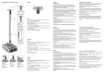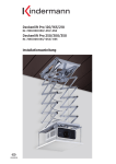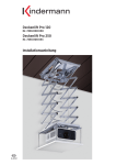
1
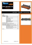
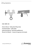
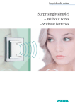
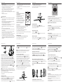
Seite / Page / Page 6
weight of the projector.
• Screw the bolts at least three turns into the drill-holes of the projector.
• If the screws are too long for the drill-holes of your projector,
use additional discs in order to prevent damages.
• The airflow of the projector is hot! Make sure that the unit keeps its
distance to other materials and that the flow of fresh air is not
hampered. The projector can be ruined by overheating.
• We are not responsible for subsequent damages in case of incompetent
mounting.
• Please keep this user manual.
•
•
•
•
•
•
•
•
•
Consignes de sécurité
L’installation doit être uniquement effectuée par du personnel qualifié.
Vérifier en tout cas la force de tenue du plafond soit suffisante pour
projecteur et support.
Utiliser uniquement des vis de grosseur suffisante, qui sont spécialement conçues pour le matériel de plafond rencontré.
Ces vis ne sont pas livrées avec le support.
Vérifier que la solidité de la matière du plafond est convenable pour un montage définitif et qu’il y a aucun risque de chute.
Les matières de plafonds convenables sont: Bois dur, poutre d’acier,
béton.
Faites un test de charge du double du poids.
Les boulons d’attache doivent être tournés au moins trois fois dans le
pied du projecteur.
Si les vis de montages sont trop longues, il faut utiliser des rondelles
supplémentaires pour ne pas endommager le projecteur.
Un montage incorrect, un plafond défectueux ou non-convenable sont
des risques potentiels pour personnes, appareil et équipement!
Le ventilateur du projecteur est chaud! Faites attention aux distances
nécessaires pour la circulation d’air et la distance aux autres matériaux.
L’appareil peut être endommagé à cause de surchauffe, ou il peut
prendre feu!
Seite / Page / Page 10
b
c
a
Seite / Page / Page 7
Seite / Page / Page 8
• Nous ne sommes pas responsables en cas de montage non-approprié et
b) Un montage avec seulement 3 bras est possible
c) Longueurs spéciales de bras sur demande
pour des préjudices ultérieurs.
• Les installations électriques ne doivent être faites que par du personnel
compétant.
• Conservez le mode d’emploi.
Achtung: Es müssen mindestens 3 Gewindegänge eingeschraubt werden. Keine Kleber oder Schmiermittel verwenden. Wenn die Montage nicht
richtig ausgeführt wird, kann der Projektor herunterfallen. Dabei besteht die
Gefahr von Verletzungen oder Unfällen.
Ziehen Sie nun alle Schrauben der vorhergehenden Schritte am
Projektorhalter fest.
Fixing the projector holder
Put your projector on a soft surface (upside down). Loosen the movable
arms with a hexagon screw driver 7 . Adjust the arms to the location of
the drill-holes of the projector (see also manual of the projector).
Choose the suitable screws and discs from of the set supplied.
First fix the 4 threaded sleeves and 4 nuts M10x1 a and adjust the height
b
b
Ø 138mm
a
b
Der Projektorhalter ist an einem Kugelgelenk
befestigt und kann rundum gedreht und
jeweils um ca. 20° geneigt werden.
Befestigung in diesem Bereich
nicht möglich!
Projector cannot be mounted
in this area!
Attaches dans ce rayon impossible!
General instructions
The maximum weight of the projector must not exceed 25 kg!
The distances can be modified in the following way:
a) The movable arms can be shortened
b) The projector can be fixed with only 3 carrying arms
c) Special lengths of the arms on demand
Projektorhalter abnehmen
Drehen Sie die Halte-/Justageschraube a ganz heraus.
Wenn Sie jetzt die Rastfeder b nach außen drücken können Sie den
Projektorhalter abnehmen.
Retirer le porte-projecteur
Le domaine d’attache peut être changé de cette façon:
a) Bras profilés peuvent être accourcis
Dévissez les vis de fixation et d‘ajustage a et enlevez-les complètement.
Si vous soulevez le ressort d‘arrêt b vous pouvez retirer le porte-projecteur.
Seite / Page / Page 11
Seite / Page / Page 12
of each arm so that they fit to the projector bottom. Then tighten the knurled
nut M10x1 b . Insert the suitable screws and discs (ill. c ) into all drill-holes
of the projector.
Dazu den Projektorhalter in die der Gewindebohrung gegenüberliegenden
Seite einhängen, durch Hochdrücken die Rastfeder b einrasten und eine der
beiden Halte-/Justageschrauben a eindrehen.
Note: At least 3 threaded passages must be fixed. Do not use glue or
lubricants. Danger: The projector could fall down and cause injuries.
Achten Sie darauf, dass die Lüfteröffnungen des Projektors frei bleiben!
Fixing the projector holder on the unit
Engage the unit in the projector holder of the ceiling mount by pressing
the centre part of the holder into the corresponding element of the ceiling
mount b until it engages. Then fasten one of the two screws a .
Make sure that the ventilation grilles of the projector are unobstructed!
Mise en place du porte-projecteur dans le support plafond
Positionnez le porte-projecteur afin que les trous soient superposés, puis
poussez vers le haut jusqu‘à verrouillage du ressort b et vissez une des deux
vis de fixation et d‘ajustage a .
Faites attention que les grilles de ventilation du projecteur ne soient pas
bloquées !
Faire attention aux consignes de sécurité!
Zum Verschieben lockern Sie die Innensechskantschraube c mit Hilfe
des beiliegenden Sechskant-Schraubendrehers 7 .
Achtung: Die Sicherungsschraube d nicht lockern!
Durch Lockern der Halte-/Justageschraube a am Kugelgelenk kann der
eingesetzte Projektor um ±180° gedreht, sowie um ca. ±20° geneigt
werden.
Adjustment – Premium 60/100/150/200
The telescope column has a range for height adjustment.
In order to adjust, loosen the screw c with the delivered screw driver 7 .
Attention: Do not loosen the safety screw d !
By loosening the rotating knob a on the ball-and-socket joint the
projector can be rotated ±180 degrees and tilted about ±20 degrees.
Possibilités de réglage – Premium 60/100/150/200
Le montage plafond est équipé d’une colonne télescopique pour le réglage
en hauteur. Afin d‘ajuster, desserrer la vis à 6 côtés c à l‘aide du tourne-vis
7 .
Attention: Ne pas dévisser la vis de sécurité d !
En dévissant la molette a de la rotule d’articulation, le projecteur peut
être tourné de ±180°, et incliné de ±20°.
c
Projektorhalter in die Deckenhalterung einsetzen
Fixation au plafond
Fixer la plaque de plafond avec quatre vis et si nécessaire avec chevilles
(non fournies) appropriées à l’endroit choisi au plafond.
Les perforations b peuvent également être utilisées pour la fixation des
pinces pour support tubulaire (No 5873000000).
Seite / Page / Page 13
Serrez ensuite toutes les vis du porte-projecteur.
b
Ceiling mounting
Mount the ceiling plate at its proper location with suitable holding screws
and plugs. The drill-holes b can also be used for fixing clamps
(No. 5873000000) and mounting the unit on a tube-shaped support.
Observe the safety instructions!
Taking off the projector holder
Informations générales
Le poids maximum du projecteur ne doit pas dépasser 25 kg!
a
b
Beachten Sie bitte die Sicherheitshinweise!
Unscrew the screw a completely.
Press against the flexible element b and take off the projector holder.
Attention: 3 pas de vis au minimum doivent être vissés. Ne pas utiliser de
colle ou de lubrifiant. Le projecteur peut tomber si le montage n’a pas été fait
correctement et peut ainsi causer blessures ou accident.
a
Halterung mit der Decke verschrauben
Befestigen Sie die Deckenplatte mit vier geeigneten, bauseitigen Schrauben
und ggf. Dübeln (bauseits) am festgelegten Ort an der Decke.
Die Bohrungen b können auch für die Anbringung der Trägerklemmen
(Nr. 5873000000) zur Montage an Rundrohr-Traversen verwendet werden.
The projector holder is mounted on a ball-and-socket joint and can be rotated
360 degrees and tilted about 20 degrees.
Fixer le porte-projecteur au projecteur
Posez le projecteur partie inférieure sur le dessus sur une surface douce.
Desserrez à l’aide du tourne-vis cruciforme 7 les bras profilés du
porte-projecteur. Orientez les bras sur les points de fixation du projecteur,
voir mode d’emploi du projecteur. Prennez du set de vis “pour fixation du
projecteur” les vis et rondelles correspondantes à votre projecteur.
Fixez selon l’illustration a les 4 vis profilées et 4 écrous M10x1, et réglez la
hauteur de chaque bras selon le socle du projecteur. Contre-serrez ensuite les
écrous moletés M10x1 à la main, b . Fixez ensuite les vis et rondelles
nécessaries selon l’illustration c dans les points de fixation du projecteur.
b
a
Le porte-projecteur est attaché à une articulation ronde, et peut être tourné
de tous les côtés et incliné de 20°.
Ø 378mm
Allgemeines
Das maximale Projektorgewicht darf 25 kg
nicht überschreiten!
Der Befestigungsbereich lässt sich durch
folgende Maßnahmen ändern:
a) Profilarme können gekürzt werden
b) Befestigung mit nur 3 Profilarmen
c) Sonderlängen der Profilarme auf Anfrage
Now tighten all other screws on the projector holder.
Projektorhalter am Gerät befestigen
Legen Sie den Projektor mit der Unterseite nach oben auf eine weiche
Unterlage. Lockern Sie mit dem Sechskant-Schraubendreher 7 die
Profilarme des Projektorhalters. Richten Sie die Profilarme auf die Befestigungsbuchsen des Projektors aus, siehe auch Anleitung des Projektors.
Entnehmen Sie aus dem Schraubensatz die für Ihren Projektor passenden
Schraubengrößen und Scheiben. Montieren Sie zuerst nach Abbildung a
die 4 Gewindehülsen und 4 Muttern M10x1, und stellen Sie die Höhe eines
jeden Armes passend zum Projektorboden ein. Ziehen Sie anschließend
die Rändelmutter M10x1 zum Kontern handfest an, b . Montieren Sie nun
die passenden Schrauben und Unterlegscheiben nach Abbildung c in alle
Befestigungsbuchsen des Projektors.
Seite / Page / Page 9
d
a
a
Justagemöglichkeiten – Premium 60/100/150/200
Zur Höheneinstellung hat das Teleskoprohr einen Einstellbereich.
Empfehlungen
Da die Fernbedienung den Projektor bei Nichtbenutzung nur in den Standby-Betrieb versetzt, empfehlen wir Ihnen, die Netzzuleitung mit einem
zusätzlichen Ein-/Ausschalter auszustatten.
Verwenden Sie für die Verkabelung nur hochwertige abgeschirmte
Verbindungskabel.
Schließen Sie die Netzleitung und alle Signalkabel lose an und nehmen
einen Projektionstest vor.
4a Middle piece – can be removed if necessary!
2 Cable blind for interior cable channel
2 x (Premium 60/100/150/200)
1 x (Premium 30)
4x
4x
Mounting kit
1 Column – Premium 60/100/150/200
Telescope device with projector holder, mounting plate and
4 carrying arms (with groove nuts)
6
4x
4a
5
10 Geteilter Baldachin (optional erhältlich – Nr. 7450 000 010)
zusammenschieben ! - nicht für Modell Premium 30 -
3a
(Alternative zur montierten Sterngriffschraube)
9
8
7
6
4 x Gewindeabstandsbuchsen
Sechskant-Schraubendreher
4 x Rändelmutter M10x1
3a 4 4a 5
Mittelteil – kann bei Bedarf ausgebrochen werden!
2
Rosette, 2-teilig zur Anbringung bei abgehängter Decke
3b Premium 30
9
Rosette, 2 éléments pour pose sur dalles de faux-plafond
Premium
• Wir haften nicht bei unsachgemäßer Montage und für Folgeschäden.
• Bitte Anleitung aufbewahren.
3b Premium 30
•
•
•
•
Screw M6x30 (alternative to mounted star grip screw)
•
7
6
4 distance bolts
Screw driver
4 x knurled nut M10x1
•
•
•
5 4 sets of fastening screws M3 / M4 / M5 / M6
4 x 2 washers (ø3.2 / ø4.3 / ø5.3 mm)
Seite / Page / Page 4
Seite / Page / Page 3
Seite / Page / Page 2
La pièce intérieure peut être enlevée si necessaire!
4 x nut M10x1
8
Lieferumfang
1 Säule – Premium 60/100/150/200
Teleskopvorrichtung mit Projektorhalter, Deckenplatte und Profilarme
(4 Stück mit Nutensteinen)
3b
4 x sets de vis M3 / M4 / M5 / M6
4 x 2 rondelles (ø3,2 / ø4,3 / ø5,3 mm)
10 2 parts cover plate (optional – No. 7450 000 010)
push together ! - not for model Premium 30 -
2 Kabelabdeckung für innenliegende Kabelführung
2 x (Premium 60/100/150/200)
1 x (Premium 30)
1
3a 4 4a 5
•
•
Livré avec
1 Colonne – Premium 60/100/150/200
Elément télescopique avec porte-projecteur, porte-plafond pour angle
et bras profilé (4 pierres de blocage)
je 4 Schrauben M3 / M4 / M5 / M6
4 x 2 U-Scheiben (ø3,2 / ø4,3 / ø5,3 mm)
Premium
6
2 Cache câble pour passage de câbles
2 x (Premium 60/100/150/200)
1 x (Premium 30)
Halte-/Justageschraube M6x30
4 x Mutter M10x1
4
7
•
4 x sets de boulons de distance
Tourne-vis 6 côtés
Sicherheitshinweise
Die Befestigung sollte nur von Fachpersonal ausgeführt werden.
Überzeugen Sie sich in jedem Fall von der ausreichenden Tragfähigkeit der Decke für Projektor und Deckenhalterung.
Benutzen Sie nur ausreichend dimensionierte Schrauben, die speziell für die vorhandene Deckenstruktur geeignet sind.
Diese Schrauben sind nicht im Lieferumfang enthalten!
Überprüfen Sie, ob das Deckenmaterial die für eine dauerhafte Montage erforderliche Festigkeit hat.
Geeignete Deckenstrukturen sind: Hartholz – Stahlträger – Beton.
Führen Sie nach der Montage einen Belastungstest mit der doppelten
Belastung durch.
Die Befestigungsschrauben für den Projektor müssen mindestens drei Umdrehungen ins Gewinde (Geräteseite) eingedreht sein
Sind die Befestigungsschrauben für die Gewindebuchsen Ihres Projektors zu lang, verwenden Sie bitte zusätzliche U-Scheiben, um Beschädigungen im Gerät zu vermeiden.
Die Abluft des Projektors ist heiß!
Auf ausreichende Belüftung und Abstände zu anderen Materialien
achten. Durch Überhitzung kann das Gerät Schaden nehmen.
Seite / Page / Page 5
Accessories
No. 7450 000 010 2 parts cover plate, 15 x 13 x 6 cm
- not for model Premium 30 (see „Mounting kit“ page 3 for application)
10
Nr. 7450 000 xx0 aluminium eloxiert / Nr. 7450 000 xx1 weiß, RAL 9003
Kindermann Premium 30 Nr. 7450 000 030/031
Abstand Projektor/Decke 30 cm fix, kann bis auf 10 cm gekürzt werden
Kindermann Premium 60 Nr. 7450 000 060/061
Höhenverstellung stufenlos von 41 bis 61 cm
Zubehör / Accessories /
Accessoires
•
8 4 x écrou moleté M10x1
4 x écrou M10x1
Technische Daten
No. 7450 000 xx0 anodized aluminium / No. 7450 000 xx1 white, RAL 9003
Kindermann Premium 30 No. 7450 000 030/031
Distance between ceiling/projector 30 cm fix, can be shortened up to 10 cm
Kindermann Premium 60 No. 7450 000 060/061
Height-adjustment stepless from 41 – 61 cm
Kindermann Premium 100 No. 7450 000 100/ 101
Height-adjustment stepless from 61 – 100 cm
Kindermann Premium 150 No. 7450 000 150/ 151
Height-adjustment stepless from 86 – 150 cm
Kindermann Premium 200 No. 7450 000 200/201
Height-adjustment stepless from 111 – 200 cm with safety rope
9
Safety instructions
The mounting should only be done by qualified personnel.
Make sure that the construction of the ceiling is suitable for
permanently holding the weight of the projector and the mounting kit.
Suitable materials to attach the mounting kit to are hard wood, metal or concrete surfaces.
Only use the proper screw dimensions which are suitable for the
construction of the ceiling.
Such screws are not included in the mounting kit!
No. 7450 000 013 Tiltable joint
for installation on ceilings with max. 45°
No. 5873 000 000 Clamps for fixing the ceiling mounting kit on a
tube-shaped support
No. 7426 000 000 Anti-theft device
No. 5883 000 002 Adapter plate for EPSON Z-serie
Technical data
7
9 Vis de fixation et d‘ajustage M6x30
(alternative pour vis montée)
• After mounting the ceiling bracket, test the construction with twice the
Alle Zuleitungen in den Kabelkanal einlegen und Kabelkanal mittels
Kabelabdeckung schließen.
Alle Verschraubungen überprüfen.
Conseils
Puisque le télécommande du projecteur, en cas de non-utilisation, ne
premet que la mise en veille, nous recommandons l’utilisation d’un
interrupteur séparé.
Utiliser pour le câblage uniquement des câbles de liaisons de haute qualité.
Brancher tous les câbles de courant et de signaux et faire un test de
projection.
Ranger les câbles dans le cannal et refermer ce dernier.
Vérifier que les vis soient serrées.
8
10 Cache double-éléments (optionel – No 7450 000 010)
Seite / Page / Page 16
Kindermann Premium 100 Nr. 7450 000 100/ 101
Höhenverstellung stufenlos von 61 bis 100 cm
Kindermann Premium 150 Nr. 7450 000 150/ 151
Höhenverstellung stufenlos von 86 bis 150 cm
Kindermann Premium 200 Nr. 7450 000 200/201
Höhenverstellung stufenlos von 111 bis 200 cm mit Seilabspannung
Zubehör
Nr. 7450 000 010 Geteilter Baldachin, 15 x 13 x 6 cm
- nicht für Modell Premium 30 (Einsatz siehe Lieferumfang!)
Nr. 7450 000 013 Neigungsgelenk
zur Montage an schrägen Decken, max. Neigung 45°
Nr. 5873 000 000 Trägerklemme zur Anbringung der Deckenhalterung an Rundrohr-Traversen
Nr. 7426 000 000 Diebstahlsicherung
Nr. 5883 000 002 Adapterplatte für EPSON Z-Serie
4x
à encastrer l‘un dans l‘autre ! - pas pour modèle Premium 30 -
3a Premium
3b Premium 30
4 Cover, 2 components, for fixing the mount with a false ceiling
Seite / Page / Page 15
Advice
As the remote control automatically switches to stand-by when the
projector is not in use, we recommend you to equip the power cable with
an additonal on/off switch.
Use only high-quality protected connection cables.
Connect the power supply and all control cables provisionally and test the
projection.
Insert all the cables into the cable channel and close it.
Check the fastening of all screws.
4x
Seite / Page / Page 14
Deckenhalterungen
Ceiling brackets
Supports plafond
Données techniques
No 7450 000 xx0 coated aluminium / No 7450 000 xx1 white, RAL 9003
Kindermann Premium 30 No 7450 000 030/031
Distance projecteur/plafond 30 cm fixe, peut être raccourci jusqu’à 10 cm
Kindermann Premium 60 No 7450 000 060/061
Réglage de la hauteur entre 41 à 61 cm
Kindermann Premium 100 No 7450 000 100/ 101
Réglage de la hauteur entre 61 à 100 cm
Kindermann Premium 150 No 7450 000 150/ 151
Réglage de la hauteur entre 86 à 150 cm
Kindermann Premium 200 No 7450 000 200/201
Réglage de la hauteur entre 111 à 200 cm avec le câble de tension
Accessoires
No 7450 000 010
No 7450 000 013
No 5873 000 000
No 7426 000 000
No 5883 000 002
Premium
Nr. 5880 000 100
Premium 30
Nr. 7450 000 030/-031
Cache en 2 éléments, 15 x 13 x 6 cm
- pas pour modèle Premium 30 (voir page 4 „Livré avec“ pour l‘attache!)
Articulation de montage
pour fixation aux plafonds de max. 45°
Pince pour attache à tubes de scène
Système anti-vol
Plaque d‘adaptation pour EPSON série Z
7450 000 030/-31/-60/-61/-100/-101/-150/-151/-200/-201 D/GB/F 2013-03/842 028
Änderungen vorbehalten / Subject to alterations / Modifications réservées
Printed in Germany
Kindermann GmbH · Mainparkring 3 · D-97246 Eibelstadt
E-Mail: [email protected] · www.kindermann.com
Premium 60
Nr. 7450 000 060/-061
Premium 100
Nr. 7450 000 100/-101
Premium 150
D
GB
F
03.2013
Nr. 7450 000 150/-151
Premium 200
Nr. 7450 000 200/-201