1
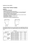
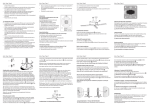
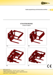
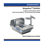
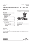
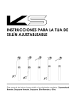
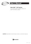
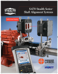
HÖHENVERSTELLBARE
SATTELSTÜTZE
BENUTZERHANDBUCH
Dieses Benutzerhandbuch behandelt folgende modelle: Supernatural,
Supernatural Remote, Supernatural Beam, Supernatural 272 Remote,
Dropzone und Dropzone Remote.
BITTE LESEN SIE DIES ZUERST
Wir danken Ihnen für den Kauf einer neuen, höhenverstellbaren
KS-Sattelstütze. Ihre neue Sattelstütze hat eine zweijährige
Garantie ab dem Einkaufsdatum. Die Garantie ist ausdrücklich
auf die Reparatur oder Ersetzung der defekten Teile begrenzt und
nur darauf. Die Garantie gilt nur für den Ersteigentümer und ist
nicht übertragbar. Ein Kaufnachweis ist notwendig um die
Garantie in Anspruch zu nehmen. Die Garantie deckt weder die
normale Abnützung und Instandhaltung, noch den falschen
Einbau oder Verwendung der Sattelstütze ab. Bei Änderungen
jeglicher Art erlischt die Garantie. Kind Shock Hi-Tech Co. Ltd.
haftet nicht für individuell anfallende Kosten die durch die
Ausführung der Garantiebestimmungen entstanden sind und die
nicht durch diese Garantie gedeckt sind. Bei jeglicher
Veränderung oder falsche Benutzung der Sattelstütze übernimmt
der Benutzer zu jeder Zeit jedes Risiko eines Schadens an seiner
Person oder Eigentum, einschließlich and der Sattelstütze, sowie
andere Verluste. Diese Garantie gibt dem Verbraucher bestimmte
Rechte, die von Land zu Land verschieden sind. Diese Garantie
beeinträchtigt nicht das gesetzliche Zurückbehaltungsrecht des
Verbrauchers.
ACHTUNG
Dies ist ein Produkt von hoher Qualität. Bei korrekter Montage und
regelmäßiger Wartung durch einen autorisierten KS-Service Center
wird es zuverlässig funktionieren. Bitte lesen Sie diese Anweisungen
durch bevor Sie Ihre neue Sattelstütze montieren und halten Sie
sich daran.
VORSICHT
Die KS höhenverstellbare Sattelstützen müssen regelmäßig von
einem autorisierten KS-Service Center gewartet werden.
Anschriften von Service Centers unter www.kssuspension.com.
Montieren Sie Ihre Sattelstütze nicht ab. Abmontieren könnte
Schäden und ernsthafte Verletzungen zur Folge haben, da einige
Bestandteile unter Druck stehen. Das Nichtbefolgen dieser
Anweisungen löscht die Garantie mit sofortiger Wirkung.
i
BENUTZERHANDBUCH
INHHALT
Englisch
1
Deutsch
13
Französisch
25
Italienisch
37
Spanisch
49
Chinesisch
61
Japanisch
73
Copyright © 2011 Kind Shock Hi-Tech Co. Ltd.
Alle Rechte vorbehalten.
ii
BEVOR SIE DIE SATTELSTÜTZE MONTIEREN
Bitte vergewissern Sie sich, dass Ihre neue Sattelstütze zu Ihrem
Rahmen passt. Alle Supernatural, Supernatural Remote,
Supernatural Beam, Dropzone und Dropzone Remote-Modelle
sind für Sattelrohr Innendurchmesser von 30,9 mm oder 31,6 mm
geeignet. Supernatural 272 ist lediglich mit einem Sattelrohr
Innendurchmesser von 27,2 mm kompatibel. Die Verwendung
einer Sattelstütze mit dem falschen Durchmesser kann
Verrutschen, ungenügende Leistung und Verletzungen, sowohl als
auch Garantieverfall verursachen.
Vergewissern Sie sich, dass Ihr Rahmen sauber und frei von
Ablagerungen und Fett ist und dass Ihr Sattelrohr glatt und
frei von allem ist, was die Sattelstütze zerkratzen könnte.
MONTAGE DER SATTELSTÜTZE
AUSRICHTUNG DER SATTELSTÜTZE
Alle Sattelstützmodelle, die durch Hebel betätigt werden
(einschließlich der hebelbetätigten Supernatural 272) sind so
ausgerichtet, dass der Betätigungshebel der Fahrradvorderseite
zugewandt ist.
Die Ausrichtung der ferngesteuerten Sattelstützen wird unten
angezeigt:
Vorderseite des Fahrrades
Rückseite des Fahrrades
Fetten Sie die Gewinde aller Bolzen der Sattelstütze ein.
Tragen Sie ein Gleitmittel auf die Innenseite des Sattelrohrs
und auf dem Teil der Sattelstütze auf, der im Sattelrohr
eingeführt wird. Verwenden Sie kein Fett.
2
1
MONTAGE DER SATTELSTÜTZE
SATTELMONTAGE
MINDESTEINFUHRUNGSTIEFE
SUPERNATURAL & SUPERNATURAL REMOTE
Alle Modelle müssen so im Sattelrohr eingeführt werden, dass die
auf
der
Sattelstütze
aufgezeichnete
Linie,
die
die
Mindesteinführungstiefe anzeigt, bedeckt ist.
Lösen
Sie
mit
einer
5mm-Inbusschlüssel
die
zwei
Hauptklemmbolzen bis diese fast frei von der oberen Hälfte der
Sattelklemme sind. Stellen Sie die vordere/hintere Position des
Sattels ein. Ziehen Sie die zwei Hauptklemmbolzen bis zu einem
maximalen Drehmoment von 15 Nm fest.
Ungenügend
tiefe
Einführung der Sattelstütze
in dem Sattelrohr kann diese
und/oder
das
Fahrrad
beschädigen und kann
darüber
hinaus
ein
Kontrollverlust
über
das
Fahrrad verursachen, was
zu ernsthafte Verletzungen
oder Tod führen kann.
13-15 N-m
SUPERNATURAL BEAM
DREHMOMENTSCHLÜSSEL FÜR DIE KLEMMSCHELLE DES SATTELROHRS
Ziehen Sie die Klemmschelle des Sattelrohrs bis zu einem
maximalen Drehmoment von 7 Nm fest. Überziehen Sie diesen
Drehmomentswert nicht, da dies die richtige Funktionsweise Ihrer
Sattelstütze beeinträchtigen könnte. Überziehen Sie nicht diesen
Drehmomentswert, da dies die richtige Funktionsweise Ihrer
Sattelstütze beeinträchtigen könnte.
Überziehen Sie nicht diesen
Drehmomentswert, da dies
die richtige Funktionsweise
Ihrer
Sattelstütze
beeinträchtigen könnte.
Die Supernatural Beam verlangt nach der Verwendung eines SDG
I-Beam™, KORE T-RAIL™ oder eines anderen kompatiblen Sattels.
Mit einem 4 mm-Inbusschlüssel lösen Sie die zwei seitlichen Bolzen
der Trägerklemme bis zwischen den Spannbacken genügend
Platz für die Sattelmontage entsteht. Installieren Sie den Sattel und
stellen Sie die vordere/hintere Position und Winkel des Sattels ein.
Ziehen Sie die zwei seitlichen Bolzen der Trägerklemme bis zu
einem maximalen Drehmoment von 10 Nm fest.
6-7 N-m
8-10 N-m
3
4
SATTELMONTAGE
MONTAGE DES FERNSTEUERUNGSHEBELS
SUPERNATURAL 272 & SUPERNATURAL 272 REMOTE
Mit einem 5 mm-Inbusschlüssel lösen Sie die zwei
Hauptklemmbolzen bis die zwei Hälften des Klemmzylinders sich
frei drehen können. Ziehen Sie die obere Hälfte des Klemmzylinders
heraus. Installieren Sie den Sattel in der richtigen Stellung mit der
unteren Hälfte des Klemmzylinders und schieben Sie die obere
Hälfte wieder ein. Stellen Sie die vordere/hintere Position und den
Winkel des Sattels ein. Ziehen Sie die zwei Hauptklemmbolzen bis zu
einem maximalen Drehmoment von 15 Nm fest.
WENDEN SIE NICHT die folgenden
hebelbetriebene Sattelposten an.
Schritte
auf
MIT STANDARDGRIFF
Lösen Sie mit einem 3 mm-Inbusschlüssel den Klemmbolzen der
Klemme des Fernsteuerungshebels und nehmen Sie ihn heraus.
Öffnen Sie die aufklappbare Hebelklemme und setzen Sie sie an
der gewünschten Stelle Ihres Lenkers auf. Schließen Sie die
Klemme und setzen Sie den Klemmbolzen wieder ein. Ziehen Sie
den Klemmbolzen bis zu einem maximalen Drehmoment von 5 Nm
fest.
13-15 N-m
DROPZONE & DROPZONE REMOTE
Lösen Sie mit einem 6 mm-Inbusschlüssel den einzelnen
Hauptklemmbolzen bis er fast frei von der oberen Hälfte der
Sattelklemme ist. Stellen Sie die vordere/hintere Position und den
Winkel des Sattels ein. Ziehen Sie den Hauptklemmbolzen bis zu
einem maximalen Drehmoment von 22 Nm fest.
4-5 N-m
MIT ODI LOCK-ON™-KOMPATIBLEM GRIFF
Die Klemme des Fernsteuerungshebels kann anstelle des inneren
Verschlussrings bei ODI LOCK-ON™-kompatible Griffe. Nehmen Sie
den inneren Verschlussring aus Ihrem Griff heraus. Ersetzen Sie ihn
durch die Klemme des Fernsteuerungshebels der Sattelstütze.
Folgen Sie die o.a. Anweisungen.
20-22 N-m
5
6
BENUTZUNG IHRER SATTELSTÜTZE
SICHERHEIT UND WARTUNG
ZUM ERSTEN MAL
VOR JEDE FAHRT
Wenn Sie Ihre Sattelstütze zum ersten Mal benutzen kann es sich
notwendig erweisen, ihr einen festen „Stubs“ nach unten zu
verpassen, um die Ursprungsbewegung in Gang zu setzen, wegen
der natürlichen Neigung der Dichtung, Öl von seiner Oberfläche
abzuweisen. Dieser Handgriff ist nur vor der ersten Benutzung, oder
nach langer nicht Benutzung notwendig. Sobald die Sattelstütze
einmal ab- und aufgefahren ist, verteilt sich Öl auf die Dichtung
und das Ganze funktioniert normal.
Prüfen Sie vor jede Fahrt, ob die Sattelstütze sicher im Rahmen sitzt
und ob alle Klemmbolzen fest gezogen sind, jeder nach
vorgeschriebenem Drehmomentwert. Vergewissern Sie sich, dass
Ihre Sattelstütze keine Anzeichen von Abnutzung oder Undichte
aufweist. Vergewissern Sie sich, dass die Sattelstütze richtig
funktioniert. Vergewissern Sie sich, dass die maximale Höhe der
Sattelstütze nicht so hoch ist, dass der Fahrer die Kontrolle über das
Fahrrad verliert.
HEBEN UND SENKEN DES SATTELS
REGELMÄSSIGE WARTUNG
Um den Sattel zu senken, Pressen Sie den Sattel mit Ihrer Hand fest
herunter oder setzen Sie sich darauf, drücken den
Fernsteuerungshebel und halten ihn gedrückt. Lassen Sie den
Hebel wieder los wenn Sie die gewünschte Höhe erreicht haben.
Ihre KS-Sattelstütze braucht regelmäßige Wartung, um voll
funktionsfähig zu bleiben. Die Wartung sollte in den gleichen
Zeitabständen wie die Reinigung des Antriebs stattfinden. Bitte
wenden Sie sich dafür an Ihrem Fachhändler. Für weitere
Informationen wenden Sie sich bitte an [email protected]
oder besuchen Sie www.kssuspension.com.
Um den Sattel zu heben, betätigen Sie Ihre Sattelstütze durch
Ziehen der Hebel- oder Lenkerfernsteuerung (je nach Modell).
Lassen Sie los wenn die richtige Höhe erreicht ist.
Sie können Ihren Sattel in jeder gewünschten Höhe innerhalb der
Länge der Sattelstütze bringen.
7
8
HEIGHT ADJUSTABLE SEATPOST
USER MANUAL
This user manual covers the following models: Supernatural, Supernatural
Remote, Supernatural Beam, Supernatural 272, Supernatural 272 Remote,
Dropzone and Dropzone Remote models.
PLEASE READ THIS FIRST
Thank you for purchasing a new KS Height Adjustable Seatpost.
Your new seatpost is warranted for a period of two years from the
date of purchase. The warranty is expressly limited to the repair or
replacement of the defective part and is the sole remedy of the
warranty. The warranty applies only to the riginal owner and is not
transferrable. Proof of purchase is required to validate warranty
eligibility. The warranty does not cover normal wear and tear,
routine maintenance, improper installation or improper use of the
seatpost. Modification of the seatpost in any manor shall void the
warranty. Kind Shock Hi-Tech Co. Ltd. shall not be responsible for
incidental or individual costs incurred by the warranty service
provider that are not covered by this warranty. The user assumes
the risk of any personal injury or property damage, including
damage to the seatpost, and any other losses, if the seatpost is
modified or improperly used at any time. This warranty gives the
consumer specific legal rights and those rights vary from state to
state. This warranty does not affect the statutory rights of the
consumer.
ATTENTION
This is a high performance product. It will give you reliable service
if it is installed properly and regularly maintained by an authorized
KS Service Center. Please read through these instructions fully and
follow them careful before you install your new seatpost.
WARNING
KS Height Adjustable Seatposts must be regularly maintained by
an authorized KS Service Center. Service center locations can be
found at www.kssuspension.com.
Do not disassemble your
seatpost.
Disassembly could cause damage and severe
personally injury as some of the contents are under pressure.
Failure to follow these warnings and instructions will immediately
void your warranty.
i
USER MANUAL
CONTENTS
English
1
German
13
French
25
Italian
37
Spanish
49
Chinese
61
Japanese
73
Copyright © 2011 Kind Shock Hi-Tech Co. Ltd.
All Rights Reserved
ii
BEFORE YOU INSTALL THE SEATPOST
SEATPOST INSTALLATION
Please be sure your new KS seatpost is designed to fit in your frame.
All Supernatural, Supernatural Remote, Supernatural Beam,
Dropzone and Dropzone Remote models are designed to fit either
30.9mm or 31.6mm seat tube inner diameters. Supernatural 272
and Supernatural 272 Remote is only compatible with 27.2mm seat
tube innter diameters. Improper fit may cause slippage, faulty
performance, injury and may result in void of warranty.
Make sure your frame is clean and free of debris, grease
and the inside of your seat tube is smooth and free of any
object that may score the seatpost.
Apply grease to all seatpost bolt threads.
SEATPOST ORIENTATION
All lever actuated seat post models (including lever actuated
Supernatural 272) are oriented with the actuation lever facing the
front of the bicycle.
The orientation of remote actuated seatpost models is shown
below:
Front of Bicycle
Rear of Bicycle
Apply a friction or anti-seize compound to the inside of the
seat tube and inserted surface of the seatpost. Do not use
grease.
2
1
SEATPOST INSTALLATION
SADDLE INSTALLATION
MINIMUM INSERTION DISTANCE
SUPERNATURAL & SUPERNATURAL REMOTE
All seat post models must be inserted into the bicycle’s seat tube
to cover the minimum insertion line indicated on the seat post.
Using a 5mm Hex wrench, loosen the two head clamp bolts until
they are nearly free of the upper half of the saddle clamp. Set the
fore/aft and angle position of the saddle. Tighten the two head
clamp bolts to a maximum torque of 15 N-m.
Insufficient insertion of the
seat post into the bicycle
frame’s seat tube could
result in damage to the seat
post and/or bicycle and
may result in a loss of control
of the bicycle which may
lead to serious injury or
death.
13-15 N-m
SUPERNATURAL BEAM
SEAT COLLAR TORQUE
Tighten your frame’s seat collar to a maximum torque of 7 N-m. Do
not over torque your frame’s seat collar as this may inhibit proper
function of your seat post.
Do not over torque your
frame’s seat collar as this
may inhibit proper function
of your seat post.
The Supernatural Beam requires the use of a SDG I-BeamTM, KORE
T-RAILTM or compatible saddle. Using a 4mm Hex wrench, loosen
the two lateral bolts on the beam clamp until there is enough
clearance in the clamp jaws to install the saddle. Install the saddle
and adjust fore/aft position and angle. Tighten the two lateral
beam clamp bolts to a maximum torque of 10 N-m.
6-7 N-m
8-10 N-m
3
4
SADDLE INSTALLATION
REMOTE LEVER INSTALLATION
SUPERNATURAL 272 & SUPERNATURAL 272 REMOTE
The following steps DO NOT apply to the lever actuated
seat posts.
Using a 5mm Hex wrench, loosen the two head clamp bolts until
the two halves of the clamping cylinder is free to rotate. Slide the
upper half of the clamping cylinder out. Align the saddle into
position with the lower half of the clamping cylinder and slide the
top half back in. Adjust fore/aft position and angle. Tighten the
two head clamp bolts to a maximum torque of 15 N-m.
WITH STANDARD GRIP
Using a 3mm Hex wrench, loosen the remote lever clamp pinch
bolt and remove the bolt. Open the hinged lever clamp and
position it in the desired location on your handlebar. Close the
clamp and install the pinch bolt. Tighten to a maximum torque of
5 N-m.
13-15 N-m
4-5 N-m
DROPZONE & DROPZONE REMOTE
Using a 6mm Hex wrench, loosen the single head clamp bolt until
it is nearly free of the upper half of the saddle clamp. Set the
fore/aft and angle position of the saddle. Tighten the head clamp
bolt to a maximum torque of 22 N-m.
TM
WITH ODI LOCK-ON COMPATIBLE GRIP
The remote lever clamp can be used to replace the inner lock ring
on ODI LOCK-ONTM compatible grips. Remove the inner lock ring
on your grip. Replace with the seat post remote lever clamp.
Follow the instructions above.
20-22 N-m
5
6
USING YOUR SEAT POST
SAFETY AND MAINTENACE
FOR THE FIRST TIME
BEFORE EACH RIDE
When using your seat post for the first time, it may be necessary to
give the post a firm downward “nudge” to start the initial
movement. This is due to the seal’s natural tendency to migrate oil
away from the seal surface. This is only necessary prior to the first
use or after a long period of non-use. Once the post is cycled
through its travel the first time, it will distribute oil on the seal and
resume its normal function.
Before each ride, check that the seat post is secure in the frame
and that all clamping bolts are tightened to their specified torque
values. Make sure that your seat post does not show sign of
excessive wear and is not leaking. Check that the seat post
functions properly. Make sure that the maximum raised position of
the seat post is not too high for the rider to properly maintain
control of the bicycle.
RAISING AND LOWERING THE SADDLE
PERIODIC MAINTENANCE
To lower the saddle, weight the saddle firmly with your hand or sit
on the bike while pressing and holding the actuation lever or
remote. Release the lever when the desired height is reached.
Your KS seat post requires periodic service to maintain consistent
function. This service should be done at the same interval as a
drivetrain cleaning. Please see your local dealer to have this
service performed. For more information, please contact KS USA
at [email protected] or visit www.kssuspension.com.
To raise the saddle, actuate your seat post by pulling the lever or
handlebar remote. Unweight the saddle and release the lever
when the desired height is reached.
You can raise and lower your saddle to any desired position within
the seat post’s travel.
7
8
MANUEL DE L'UTILISATEUR D’UNE
TIGE DE SELLE TELESCOPIQUE
Ce manuel de l'utilisateur couvre les modèles suivants: Supernatural,
Supernatural Remote, Supernatural Beam, Supernatural 272, Supernatural
272 Éloignés Remote, Dropzone et Dropzone Remote.
MERCI DE LIRE CECI EN PREMIER
Merci d’avoir acheté une nouvelle tige de selle télescopique KS.
Votre nouvelle tige de selle est garantie pour une durée de deux
ans à partir de la date d'achat. La garantie est expressément
limitée à la réparation ou le remplacement de la partie
défectueuse qui est la fonction unique de la Garantie. La garantie
s'applique seulement au propriétaire original et n'est pas
transmissible. La preuve d'achat est exigée pour valider l’éligibilité
de la garantie. La garantie ne couvre pas l'usure normale.
L’entretien de routine, une installation incorrecte ou une utilisation
incorrecte de la tige de selle. La modification de la tige de selle de
quelque façon que ce soit annulera la garantie. Kind Shock
Hi-Tech Co. Ltd. ne sera pas responsable des coûts fortuits ou
individuels encourus par le service de garantie du fournisseur qui
n'est pas couvert selon cette garantie. L'utilisateur assume le risque
de n'importe quelle blessure personnelle ou endommagement de
ses propriétés, incluant des dégâts à la tige de selle et des autres
pertes, si la tige de selle est modifiée ou incorrectement utilisée à
tout moment. Cette garantie donne au consommateur des droits
légaux spécifiques et ces droits varient d’un État à un autre. Cette
garantie n'affecte pas les droits statutaires du consommateur.
ATTENTION
Ceci est un produit de haute performance. Il vous donnera un
service fiable. S’il est installé correctement et régulièrement
entretenu par un Centre de Service KS autorisé. S'il vous plaît
veuillez parcourir ces instructions entièrement et suivez-les
prudemment avant d’installer votre nouvelle tige de selle.
WARNING
La tige de selle télescopique réglable KS doit être régulièrement
entretenue par un Centre de Service KS autorisé. Vous pouvez
trouvez les centres service KS sur www.kssuspension.com. Ne
démontez pas votre tige de selle. Le désassemblage pourrait
causer des dommages et de sévères blessures personnelles, une
partie du contenu étant sous pression. Ne pas suivre ces
avertissements et instructions annulera immédiatement votre
garantie.
i
MANUEL POUR L'UTILISATION
CONTENU
Anglais
1
Allemand
13
Français
25
Italien
37
Espagnol
49
Chinois
61
Japonais
73
Copyright © 2011 Kind Shock Hi-Tech Co. Ltd.
Tous Droits Réservés.
ii
AVANT QUE VOUS N'INSTALLIEZ LA TIGE DE SELLE
Merci de vous assurer que votre nouvelle tige de selle KS est
conçue pour aller dans votre cadre. Toute la gamme
Supernatural, Supernatural Remote, Supernatural Beam,
Dropzone et Dropzone Remote sont conçues pour aller sur du
30.9mm ou 31.6mm diamètre intérieur des tubes de selle. Les
Supernatural 272 sont seulement compatibles avec un tube de
selle de diamètre intérieur 27.2mm. Un tube de selle qui n’est pas
aux bonnes dimensions peut causer des glissements, de
mauvaises performances, des blessures et peut entraîner une
annulation de la garantie.
Assurez-vous que votre cadre est propre et sans saleté,
exempt de graisse et que l'intérieur de votre tube de selle
est lisse et sans aucun objet qui peuvent marquer la tige de
selle.
INSTALLATION DE LA TIGE DE SELLE
ORIENTATION DE LA TIGE DE SELLE
Tous les leviers de tige de selle des modèles (incluant le levier
d’activation des Supernatural 272) sont orientés avec le levier de
mise en action faisant face à l’avant du vélo.
Voir l'orientation des modèles de tige de selle activés avec des
remote Ci-dessous:
Avant du vélo
Arrière du vélo
Appliquez de la graisse à tous les filetages de boulons de la
tige de selle.
Appliquez une patte anti frictions à l'intérieur du tube de
selle et sur la surface de la tige de selle. N'utiliser pas de
graisse.
2
1
INSTALLATION DE LA TIGE DE SELLE
INSTALLATION DE LA SELLE
DISTANCE D’INSERTION MINIMALE
SUPERNATURAL & SUPERNATURAL REMOTE
Tous les modèles de tige de selle doivent êtres insérés dans le tube
de selle de la bicyclette de manière à couvrir la ligne d'insertion
minimale indiquée sur la tige de selle.
Utiliser une Clé hexagonale de 5mm, desserrez les deux boulons
d'attache principaux jusqu'à ce qu’ils soient presque à la moitié
supérieure de l'attache de selle. Régler la position avant/arrière et
sa position angulaire. Serrez les deux têtes de boulons d'attache à
un couple de serrage maximal de 15 N-m.
Une insertion insuffisante de
la tige de selle dans le
cadre pourrait avoir comme
résultat des dégâts sur la
tige de selle et/ou sur le
cadre de la bicyclette et
peut aboutir à une perte de
contrôle de la bicyclette qui
peut entraîner des blessures
sérieuses ou la mort.
13-15 N-m
SUPERNATURAL BEAM
SERRAGE DU COLLIER DE TIGE DE SELLE
Serrez le collier de serrage de votre cadre à un couple de serrage
maximal de 7 N-m. Ne pas serrer excessivement le collier du tube
de selle de votre cadre car cela peut détériorer votre tube de
selle et le rendre inutilisable.
Ne pas serrer excessivement
le collier du tube de selle de
votre cadre car cela peut
détériorer votre tube de
selle et le rendre inutilisable.
La Supernatural Beam exige l'utilisation d'une selle SDG I-BeamTM,
KORE T-RAILTM ou selle compatible. Utiliser une Clé hexagonale de
4mm, desserrez les deux boulons latéraux des mâchoires jusqu'à
ce qu’ils y aient assez de dégagement dans les mâchoires
d'attache pour installer la selle. Installez la selle et ajustez la
position avant/arrière et l'angle. Serrez les deux boulons latéraux
d'attache des mâchoires à un couple de serrage maximal de 10
N-m.
6-7 N-m
8-10 N-m
3
4
INSTALLATION DE LA SELLE
INSTALLATION DU REMOTE LEVER
SUPERNATURAL 272 & SUPERNATURAL 272 REMOTE
Les étapes suivantes ne s'appliquent pas au levier situé sur
la tige de selle.
Utiliser une Clé hexagonale de 5mm, desserrez les deux boulons
d'attache principaux jusqu'à ce que la moitié du cylindre de
serrage soit libre de tourner. Faire coulisser la moitié supérieure du
cylindre de serrage. Alignez la selle en position avec la moitié
inférieure du cylindre de serrage et faire coulisser la moitié
supérieure en place. Ajustez la position avant/arrière et l'angle.
Serrer les deux têtes des boulons à un couple de serrage maximal
de 15 N-m.
13-15 N-m
DROPZONE & DROPZONE REMOTE
EN MONTAGE STANDARD
Utiliser une Clé hexagonale de 3mm, desserrez l'attache du levier
et retirer le boulon. Ouvrez l'attache du levier à charnière et
positionner le dans la positon désirée sur votre guidon. Fermer
l'attache et installer le boulon de serrage. Serrez à un couple de
serrage de 5 N-m.
4-5 N-m
TM
AVEC GRIP COMPATIBLE ODI LOCK-ON
Utiliser une Clé hexagonale de 6mm, desserrez le seul boulon
d'attache principal jusqu'à la moitié supérieure de l'attache de
selle. Ajustez la position avant/arrière et l'angle. Serrez le boulon
principal à un couple de serrage maximal de 22 N-m.
L'attache de levier peut être utilisée pour remplacer le lock de
TM
serrage intérieur sur les poignées compatibles LOCK-ON d'ODI.
Enlevez l'anneau de serrage intérieur sur votre poignée et montez
le levier de la commande de la tige de selle. Suivez les instructions
ci-dessous.
20-22 N-m
5
6
UTILISATION DE VOTRE TIGE DE SELLE
SÉCURITÉ ET MAINTENACE
POUR LA PREMIERE FOIS
AVANT CHAQUE UTILISATION
Lorsque vous utilisez votre tige de selle pour la première fois, il peut
être nécessaire de donner à la tige une pression de haut en bas
pour commencer le mouvement initial. Cela résulte de la
tendance naturelle du joint de séparer l’huile de la surface de la
tige. Ceci est seulement nécessaire avant la première utilisation ou
après une longue période de non utilisation. Une fois que la tige
de selle aura fonctionné pour la première fois, l’huile se
redéposera sur le joint qui reprendra sa fonction normale.
Avant chaque utilisation vérifiez que la tige de selle soit
correctement sécurisée dans le cadre et que tous les boulons de
serrage soient serrés à leur couple de serrage indiqué.
Assurez-vous que votre tige de selle ne montre pas de signe
d’usure excessive et ne fuit pas. Vérifiez si la tige de selle
fonctionne correctement. Assurez-vous que la position haute de la
tige de selle n'est pas trop haute pour le cycliste pour
correctement maintenir le contrôle de la bicyclette.
LEVER ET BAISSER LA SELLE
MAINTENANCE PÉRIODIQUE
Pour baisser la selle, appuyer sur la selle fermement avec votre
main ou asseyez vous sur le vélo en appuyant et appuyez sur le
levier de mise en action ou le levier « remote». Libérez le levier
quand la hauteur désirée est atteinte.
Votre tige de selle KS nécessite un service périodique d’entretien
pour garantir son parfait fonctionnement. Ce service doit être fait
au même intervalle qu'un nettoyage de transmission. Veuillez vous
rapprocher de votre revendeur local pour effectuer ce service.
Pour plus d'informations, contactez s'il vous plaît les KS USA à
[email protected] ou visitez www.kssuspension.com.
Pour augmenter la hauteur de la selle, actionnez votre tige de
selle en tirant le levier ou sur le bouton « remote » sur le guidon
(selon modèle). Libérez le levier quand la hauteur désirée est
atteinte. Vous pouvez augmenter et baisser votre selle à n'importe
quelle position désirée dans le débattement de votre tige de selle.
7
8