1
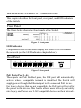
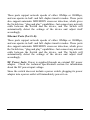
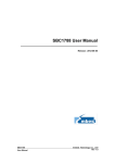
D-Link
DES-1008PA
8-Port 10/100Mbps
IEEE802.3af Switch
User’s Guide
FCC Warning
This equipment has been tested and found to comply with the
regulations for a Class B digital device, pursuant to Part 15 of the FCC
Rules. These limits are designed to provide reasonable protection
against harmful interference when the equipment is operated in a
commercial environment. This equipment generates, uses, and can
radiate radio frequency energy and, if not installed and used in
accordance with this user’s guide, may cause harmful interference to
radio communications. Operation of this equipment in a residential
area is likely to cause harmful interference, in which case the user will
be required to correct the interference at his/her own expense.
CE Mark Warning
This is a Class B product. In a domestic environment, this product
may cause radio interference, in which case the user may be required
to take adequate measures.
VCCI Warning
This is a product of VCCI Class B Compliance.
i
UL Warning
a) Elevated Operating Ambient Temperature- If installed in a closed
or multi-unit rack assembly, the operating ambient temperature of the
rack environment may be greater than room ambient. Therefore,
consideration should be given to installing the equipment in an
environment compatible with the manufacturer's maximum rated
ambient temperature (Tmra).
b) Reduced Air Flow- Installation of the equipment in a rack should
be such that the amount of air flow required for safe operation of the
equipment is not compromised.
c) Mechanical Loading- mounting of the equipment in the rack
should be such that a hazardous condition is not achieved due to
uneven mechanical loading.
d) Circuit Overloading- Consideration should be given to the
connection of the equipment to the supply circuit and the effect that
overloading of circuits might have on over current protection and
supply wiring. Appropriate consideration of equipment nameplate
ratings should be used when addressing this concern.
e) Reliable Earthing- Reliable earthing of rack-mounted equipment
should be maintained. Particular attention should be given to supply
connections other than direct connections to the branch circuit (e.g.,
use of power strips).
The PoE is intended to be connected to not exposed (outside plant)
networks or equivalent.
ii
TABLE OF CONTENTS
About This Guide................................................................................. 1
Purpose ............................................................................................ 1
Terms/Usage .................................................................................... 1
Introduction.......................................................................................... 3
Fast Ethernet Technology ................................................................ 3
Switching Technology ..................................................................... 4
Power over Ethernet (PoE) .............................................................. 5
Features............................................................................................ 5
Unpacking and Installation .................................................................. 6
Unpacking........................................................................................ 6
Installation ....................................................................................... 6
Connecting Network Cable.............................................................. 7
Identifying External Components ........................................................ 8
Front Panel....................................................................................... 8
Rear Panel ........................................................................................ 8
Understanding LED Indicators .......................................................... 10
System LED................................................................................... 10
PoE status LEDs (Port 1 ~ Port 4) ................................................. 10
Ethernet port status LEDs (Ports 1~8) ........................................... 11
PoE Rule ........................................................................................ 11
Technical Specifications .................................................................... 15
iii
ABOUT THIS GUIDE
Congratulations on your purchase of the D-Link DES-1008PA, an 8Port 10/100Mbps Fast Ethernet Switch with 4-Port PoE. This Switch
integrates 100Mbps Fast Ethernet and 10Mbps Ethernet network
capabilities in a highly flexible package. Port-1 to Port-4 on the switch
support Power over Ethernet (PoE), meaning it will automatically
detect the presence of an IEEE 802.3af-compliant powered device (PD)
and provide power through the port. The switch provides up to 15.4 W
per PoE port and can be used to power WLAN access points, IP
phones, video cameras, and other PD devices. The Switch will
automatically detect the network appliance’s requirements, and will
supply the required power to each appliance accordingly.
Purpose
This guide discusses how to install your 8-Port 10/100Mbps Fast
Ethernet Switch with 4-Port PoE.
Terms/Usage
In this guide, the term “Switch” (first letter upper case) refers to your
8-Port 10/100Mbps Fast Ethernet Switch with 4-Port PoE and
“switch” (first letter lower case) refers to other Ethernet switches.
1
INTRODUCTION
This chapter describes the features of the D-Link DES-1008PA Fast
Ethernet PoE Switch and some background information about
Ethernet/Fast Ethernet, Switching and Power over Ethernet
technology.
Fast Ethernet Technology
The growing importance of LANs and the increasing complexity of
desktop computing applications are fueling the need for high
performance networks. A number of high-speed LAN technologies
have been proposed to provide greater bandwidth and improve
client/server response times. Among them, 100BASE-TX (Fast
Ethernet) provides a non-disruptive, smooth evolution from the
current 10BASE-T technology.
100Mbps Fast Ethernet is a standard specified by the IEEE 802.3
LAN committee. It is an extension of the 10Mbps Ethernet standard
with the ability to transmit and receive data at 100Mbps, while
maintaining the CSMA/CD Ethernet protocol. Since the 100Mbps
Fast Ethernet is compatible with all other 10Mbps Ethernet
environments, it provides a straightforward upgrade and takes
advantage of the existing investment in hardware, software, and
personnel training.
2
Switching Technology
Another approach to pushing beyond the limits of Ethernet technology
is the development of switching technology. A switch bridges
Ethernet packets at the MAC address level of the Ethernet protocol
transmitting among connected Ethernet or Fast Ethernet LAN
segments.
Switching is a cost-effective way of increasing the total network
capacity available to users on a local area network. A switch increases
capacity and decreases network loading by dividing a local area
network into different segments, which don’t compete with each other
for network transmission capacity.
The switch acts as a high-speed selective bridge between the
individual segments. The switch, without interfering with any other
segments, automatically forwards traffic that needs to go from one
segment to another. By doing this the total network capacity is
multiplied, while still maintaining the same network cabling and
adapter cards.
Switching LAN technology is a marked improvement over the
previous generation of network bridges, which were characterized by
higher latencies. Routers have also been used to segment local area
networks, but the cost of a router, the setup and maintenance required
make routers relatively impractical. Today switches are an ideal
solution to most kinds of local area network congestion problems.
3
Power over Ethernet (PoE)
Power over Ethernet (PoE) integrates power and data onto one single
cabling infrastructure, eliminating the need to have AC power
available at all locations.
Power and Data is integrated onto the same cable, supporting category
5/5e up to 100 Meters. PoE will provide power to PoE compatible
devices, such as IP telephones, wireless LAN access points and IP
security cameras.
PoE is already widely adopted in the market, saving up to 50% of
overall installation costs by eliminating the need to install separate
electrical wiring and power outlets.
Features
8 ×10/100Mbps Auto-negotiation Fast Ethernet RJ45 ports with
4-port PoE function (port-1 ~ port-4)
Compliant with 802.3af specification
Supports PoE power up to 15.4W for PoE Port 1 to 4
Supports PoE power up to 52W for PoE Port 1 to 4
Supports PoE IEEE802.3af compliant Powered Device (PD)
Each port supports auto MDI/MDIX, so there is no need to use
cross-over cables or an up-link port
Full/half duplex transfer mode for each port
Wire speed reception and transmission
Up to 1K unicast addresses entities per device, self-learning, and
table aging
96KBytes packet buffer
Supports IEEE 802.3x flow control for full-duplex mode ports
Supports Back-pressure flow control for half-duplex mode ports
4
UNPACKING AND INSTALLATION
This chapter provides unpacking and installation information for the
Switch.
Unpacking
Open the shipping cartons of the Switch and carefully unpack its
contents. The carton should contain the following items:
One DES-1008PA
One AC power adapter
Four rubber feet to be used for shock cushioning
User’s Guide
If any item is found missing or damaged, please contact your local
reseller for replacement.
Installation
The setup of the Switch can be performed using the following steps:
The surface must support at least 1.5 Kg (3.5 lbs) for the Switch.
The power outlet should be within 1.82 meters (6 feet) of the
Switch.
Visually inspect the DC power jack and make sure that it is fully
secured to the power adapter.
Make sure that there is proper heat dissipation from and
adequate ventilation around the Switch. Do not place heavy
objects on the Switch.
Note: Be sure to connect 48V/1.25A power adapter DC plug to DC
jack of DES-1008PA before plugging the power cord to AC power
outlet.
5
Connecting Network Cable
The Switch support 8 10/100Mbps Ethernet ports and Port 1 ~ port 4
are PoE Enabled ports, these PoE port will automatically activate
when a compatible terminal is identified. The Switch will supply
power through the Ethernet port to the connected PoE powered device
(PD).
For legacy devices that are not compatible, the PoE port will not offer
power to this device. This feature allows users to freely and safely mix
legacy and Power over LAN compatible devices on their network.
The Switch supports 10Mbps Ethernet or 100Mbps Fast Ethernet and
it runs both in half and full duplex mode using two pair of Category 5
cable.
These RJ45 ports are Auto-MDI type port. The Switch can auto
negotiate to MDI-II or MDI-X type, so you can connect any RJ-45
cable regardless if it is a standard or crossover cable.
6
IDENTIFYING EXTERNAL COMPONENTS
This chapter describes the front panel, rear panel, and LED indicators
of the Switch.
Front Panel
The figure below shows the front panels of the Switch.
Figure 1. Front panel
LED Indicator:
Comprehensive LED indicators display the status of the switch and
the network (see the LED Indicators chapter below).
Rear Panel
Figure 2. Rear panel
PoE Ports (Port 1~4):
These ports are PoE Enabled ports, the PoE port will automatically
activate when a compatible terminal is identified. The Switch will
supply power through the Ethernet port to the connected PoE device.
For legacy devices that are not compatible, the PoE port will not offer
the power to this device. This feature allows users to freely and safely
mix legacy and Power over LAN compatible devices on their network.
7
These ports support network speeds of either 10Mbps or 100Mbps,
and can operate in half- and full- duplex transfer modes. These ports
also support automatic MDI/MDIX crossover detection, which gives
the Switch true, “plug and play” capabilities. Just connect any network
cable between the Switch and the device, and The Switch will
automatically detect the settings of the device and adjust itself
accordingly.
Ethernet Ports (Port 5~8):
These ports support network speeds of either 10Mbps or 100Mbps,
and can operate in half- and full- duplex transfer modes. These ports
also support automatic MDI/MDIX crossover detection, which gives
the Switch true, “plug and play” capabilities. Just connect any network
cable between the Switch and the device, and The Switch will
automatically detect the settings of the device and adjust itself
accordingly.
DC Power Jack: Power is supplied through an external DC power
adapter. Check the technical specification section for information
about the DC power input voltage.
Since the switch does not include a power switch, plugging its power
adapter into a power outlet will immediately power it on.
8
UNDERSTANDING LED INDICATORS
The front panel LEDs provides instant status feedback, and helps
monitor and troubleshoot when needed.
Figure 3. LED indicators of the Switch
System LED
PWR: (Power Indicator)
On
: Power On
Off
: Power Off
PoE status LEDs (Port 1 ~ Port 4)
PoE Status:
Green
:
When the PoE powered device (PD) is connected and the port supplies
power successfully.
When the PoE port has failed, possibly due to:
PoE power circuit shortage
Power over current: over the power current of PD’s
classification
Out of PoE voltage of 44 ~ 57 VDC output
Red
:
Off
: No PoE powered device (PD) connected.
9
PoE MAX
Green
When the power output to PDs is over 42W. No additional PDs can be
powered.
Off
When the system is using less than 42W
Blinking
Green
After the power output to PDs has reached or exceeded the maximum
power budget, if the user unplugged certain PDs and made the system
power left over 10W, the PoE MAX will blink 2 minutes.
Ethernet port status LEDs (Ports 1~8)
10/100M Link/ACT:
When the 10M LED lights on, the respective port is successfully
connected to 10M Ethernet network. Otherwise, when the 10M LED is
blinking, the port is transmitting or receiving data on the Ethernet
network.
10M
:
100M
When the 100M LED lights on, the respective port is successfully
connected to 100M Fast Ethernet network. Otherwise, when the 100M
:
LED is blinking, the port is transmitting or receiving data on the Fast
Ethernet network.
Off
: No link.
PoE Rule
POE M ax: this function will help to protect the POE Switch and to
stabilize the power transmitting to the powered device (PD).
If the system power usage is >= 42, the POE MAX LED will turn on
and the system will not provide power to the additional POE PD. This
is done to protect the POE Switch itself and to stabilize the power
transmitting to the other POE PDs plugged into the Switch.
10
For example: There are POE PDs connected to the POE Switch and
the total power consumption is 48 watts. The system will reserve 4
watts for a buffer and the POE MAX LED will light up. Once there is
another POE PD inserted, the system will not provide power to the
additional POE PD.
Priority: This function will help protect the system when the system
power is overloaded. The system will disable the PoE function of
lower priority PoE ports to maintain the power to higher priority PoE
ports.
The total power resource for the system is 52W shared between the 4
POE ports (maximum power for per port is 15.4W). If all POE PDs
power consumption is over 52W, the system will automatically
arrange the priority of these ports. The lower port number will have
the higher priority and the higher port number will have a lower
priority (Highest priority: Port 1 > Port 2 > Port 3 > Port 4).
For example: In this POE Switch, Port 2 is using 15 watts and Port 3,4
is using 15.4 watts, these two ports are using 45.8 watts total. If there
is an additional POE PD inserted to Port 1 with 15.4 watts, the system
power resource is over current and the priority function will activate.
The priority will be applied to the lowest port number to highest port
number, so Port 1,3 will use 15.4 watts, Port 2 will use 15 watts, and
the system will cut off the power to Port 4 due to over current.
11
TECHNICAL SPECIFICATIONS
General
Standards
IEEE 802.3 10BASE-T Ethernet
IEEE 802.3u 100BASE-TX Fast Ethernet
IEEE 802.3x Full Duplex Flow Control
IEEE 802.3af Power over Ethernet
Protocol
Data Transfer Rate
CSMA/CD
Ethernet: 10Mbps (half duplex), 20Mbps (full-duplex)
Fast Ethernet: 100Mbps (half duplex), 200Mbps (full-duplex)
Topology
Network Cables
Star
10BASET: 2-pair UTP Cat. 3, 4, 5; up to 100m
100BASE-TX: 2-pair UTP Cat. 5; up to 100m
Number of Ports
4 × 10/100Mbps Auto-MDIX RJ45 ports with POE enabled (port 1 ~ port 4)
4 × 10/100Mbps Auto-MDIX RJ45 ports (port 5 ~ port 8)
PoE Power on RJ-45
Power+: ping 3 & ping 6
Power-: ping 1 & ping 2
Physical and Environmental
DC inputs
48VDC/1.25A
Power Consumption
6.3 watts. (max. no PD device connected)
63 watts (max. with 52w PoE Device connected)
Temperature
Operating: 0° ~ 40° C, Storage: -10° ~ 70° C
Humidity
Operating: 10% ~ 90%, Storage: 5% ~ 90%
Dimensions
171 x 98 x 29 mm
EMI:
FCC Class B, CE Mark Class B, VCCI Class B
Safety:
cUL(UL60950), CB(IEC60950)
12
Performance
RAM Buffer:
96K bytes per device
Filtering Address Table:
1K entries per device
Packet
Filtering/Forwarding Rate:
10Mbps Ethernet: 14,880/pps
100Mbps Fast Ethernet: 148,800/pps
MAC Address Learning:
Automatic update
Transmits Method:
Store-and-forward
13