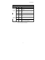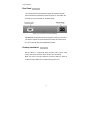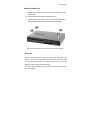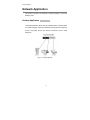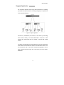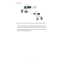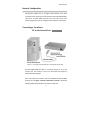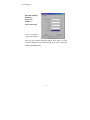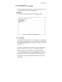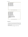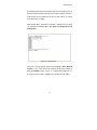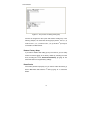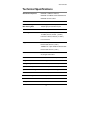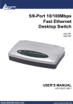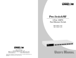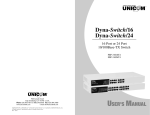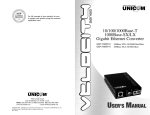
1
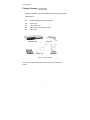
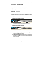
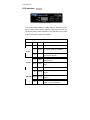
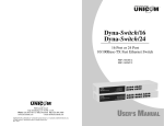
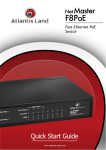
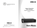
Smart-Switch/801
8 Port 10/100Base-TX Switch
with 100Base-FX
SC/MM
ST/MM
SC/SM
FEP-30109T-C
FEP-30109T-T
FEP-30109T-C-SM
Model shown: FEP-30109T-C
908 Canada Court
City of Industry, CA 91748 U.S.A.
Phone: 626.964.7873 or 800.346.6668 Fax: 626.964.7880
www.unicomlink.com
e-mail: [email protected]
©UNICOM 2005. UNICOM and “A Network Systems Solution” are trademarks of UNICOM Electric, Inc.
All rights reserved. Specifications subject to change without notice.
Rev: 09.05
USER’S MANUAL
Smart-Switch/801
Features
Conforms to IEEE 802.3, 802.3u, and 802.3x Ethernet Standards
Eight auto-sensing 10/100Mbps Ethernet RJ-45 ports
Automatic MDI/MDIX crossover for each 10/100Base-TX port
One Fixed 100Mbps Fiber port (SC/ST-Multi-Mode, SC-Single
Mode)
Back-Pressure-Base flow control on Half-duplex mode
Pause-Frame-Base flow control on Full-duplex mode
Store-and-forward architecture for abnormal packet filtering
2K-entry MAC address table
96Kbytes memory buffer sharing
Non-blocking and Full wire speed forwarding rate
One console port for VLAN configuration and Port Setting
LED-indicators for Power, 10/100, LK/ACT, and FD/COL
10" Desktop size design
1
Smart-Switch/801
Package Contents
Unpack the contents of the Smart-Switch/801 and verify them against the
checklist below.
Smart-Switch/801 Fast Ethernet Switch
Power Cord
Four Rubber Feet
RS-232 console management cable
User Guide
Smart-Switch/801
Rubber Feet
Power Cord
RS-232 cable
User Guide
Figure 1-2. Package Contents
If any item is missing or damaged, please contact your local dealer for
service.
2
Smart-Switch/801
Hardware Description
This section describes the hardware of the Smart-Switch/801.
The physical dimensions of the Smart-Switch/801 are 250mm x 132mm x
37mm (L x W x H)
Front Panel
The Front Panel of the Smart-Switch/801 consists of eight auto-sensing
10/100Mbps Ethernet RJ-45 ports with automatic MDI/MDIX, one 100BaseFX fiber port, and the LED indicators.
Smart-Switch/801 with SC Connector
Figure 2-2. The Front Panel of the Smart-Switch/801 with SC connector
Smart-Switch/801 with ST Connector
Figure 2-3. The Front Panel of the Smart-Switch/801 with ST connector
RJ-45 Ports (Auto MDI/MDIX): Eight 10/100 auto- sensing for
10Base-T or 100Base-TX connections.
100Base-FX Fiber Port: The operating range for the Multi-Mode
fiber option is up to 2Km while the SC Single Mode fiber variant can
support up to 30Km.
3
Smart-Switch/801
LED Indicators
Figure 2-4. LED Indicators
There are three LED Indicators (10/100M, LNK/ACT, FDX/COL) for each
UTP port and two LED Indicators (LNK/ACT, FDX/COL) for the fiber port.
The following table provides descriptions of the LED status. They provide
a real-time indication of systematic operation.
UTP Ports
LED
Power
Status
Color
On
Green
Power On
On
Green
The port is operating at 100Mbps.
10/100
The port is operating at 10Mbps
Off
LK /ACT
or no device attached
On
Green
Blinks
Green
Off
On
FDX /COL Blinks
Off
Description
The port is successfully connecting
with the device.
The port is receiving or transmitting
data.
No device attached.
Orange
Orange
The port is operating in Full-duplex
mode.
Collision of Packets occurring within
the port.
The port is operating in Half-duplex
mode or no device attached.
4
Smart-Switch/801
Fiber Port
LED
LK /ACT
Status
Color
On
Green
Blinks
Green
Off
FDX /COL
The port is successfully connecting with
the device.
The port is receiving or transmitting
data.
No device attached.
On
Orange
Blinks
Orange
Off
Description
The port is operating in Full-duplex
mode.
Collision of Packets occurring within the
port.
The port is operating in Half-duplex
mode or no device attached.
Table 2-1. Descriptions of LED Indicators
5
Smart-Switch/801
Rear Panel
The Console port and 3-pronged power plugs are located at the Rear
Panel of the Smart -Switch/801 as shown in Figure 2-8. This Switch will
work with AC in the 100-240V AC, 50-60Hz. Range.
Figure 2-5 The Rear Panel of the Smart-Switch/801
Console Port: Configuration is done through the console port connector.
This requires a direct connection between the switch and a device such
as a PC or terminal using the supplied RS-232 cable.
Desktop Installation
Set the switch on a sufficiently large flat space with a power outlet
nearby. The surface should be clean, smooth, level, and sturdy.
Make sure there is enough clearance around the Switch to allow air
circulation and the attachment of cables and the power cord.
6
Smart-Switch/801
Attaching Rubber Feet
A_ Make sure mounting surface on the bottom of the Switch is grease
and dust free.
B_ Remove adhesive backing from the Rubber Feet.
C_ Apply the Rubber Feet to each corner on the bottom of the Switch.
These footpads protect the Switch from shock and vibration.
Figure 2-6. Attaching Rubber Feet to each corner on the bottom of the Switch
Power On
Connect the power cord to the power socket on the rear panel of the
Switch. The other end of the power cord connects to the power outlet.
The internal power supply in the Switch works with AC in the 100240VAC, frequency 50~60Hz voltage range.
Check the power indicator on the front panel to ensure that power is
properly supplied.
7
Smart-Switch/801
Network Application
This section provides a few samples of network topology in which the
Switch is used.
Desktop Application
The Smart-Switch/801 can be used as a desktop switch, an ideal solution
for a small workgroup. Used as a standalone switch, personal computers,
servers, and printer servers are directly connected to form a small
workgroup.
Figure 3-1. Desktop Application
8
Smart-Switch/801
Segment Application
For enterprise networks where large data broadcast are constantly
processed, this switch is ideal for connecting workgroups or departments
to the corporate backbone.
Figure 3-2. Segment Applications
Connect PCs, workstations, and servers to each other by connecting
these devices directly to the Smart-Switch/801. All devices in this
network can communicate with one another as well as with central
servers.
The Switch automatically learns node addresses, which are subsequently
used to filter and forward all traffic based on the destination address. You
can interconnect each of your small, switched workgroups to form a
larger switched network through any of the RJ-45 ports of the SmartSwitch/801.
9
Smart-Switch/801
Smart-Switch/801
Fiber Optic
Connection
(2km - MM)
(30km - SM)
200Mbps
Smart-Switch/801
COMPUTER
PRINTER
SERVER
COMPUTER
Figure 3-3. Use fiber port (Smart-Switch/801) to extend the distance between workgroups
In the above illustration, two Smart-Switch/801 switches are used to
connect two small workgroups. By using fiber ports to connect switches,
the distance between the two switches can extend up to 2Km (MultiMode) or 30Km (Single Mode fiber).
10
Smart-Switch/801
Network Configuration
This Section explains how to configure VLAN features via a direct
connection to the console port on the rear panel of the Smart-Switch/801.
This port is a female DB-9 connector. From the main menu of the
console program, the user can configure various functions of the switch.
Connecting a Terminal or
PC to the Console Port
Figure 4-1. Connecting the Smart-Switch/801 to a terminal via RS-232 cable
Use the supplied RS-232 cable to connect a terminal or PC to the
console port. The terminal or PC to be connected must support a
terminal emulation program.
Once connected, turn on the PC and run a standard terminal emulation
program such as Hyper Terminal or Windows Terminal to match the
following default characteristics of the switch console port:
11
Smart-Switch/801
Baud Rate: 9600 bps
Data Bits: 8
Parity: none
Stop Bit: 1
Flow Control: None
Figure 4-2. The settings of
communication parameters
After you have finished parameter settings, press “OK“. The main
console management menu should appear. (You need to reboot the
Switch to show Main Menu)
12
Smart-Switch/801
Console Management
Console Configuration enables use of a local console terminal or PC to
control ports and VLANs on the Smart-Switch/801.
Main Menu
The Main Menu shows all available switch configuration options.
Figure 4-3. The Main Menu of Console Management
Per Port Setting
From the Main Menu, choose the 1st Item by typing “ 1 “ into the blank.
The following screen appears (see fig 4-4). The default Per Port Settings
are all Auto Negotiation and the default fiber port setting is 100M / Fullduplex mode.
To modify a port's status, first choose the port number. In the following
example, we choose Port 1 by typing “1". Five different port duplex
modes are available: Auto-Negotiation, Force to 100M and FDX mode,
Force to 10M and FDX mode, Force to 100M and HDX mode, Force to 10M
and HDX mode. The Fiber port also features four configurable modes.
(see Figure 4-5). Type in the required item number here to set the port
duplex mode.
13
Smart-Switch/801
Figure 4-4. The default Per Port Setting
Figure 4-5. Port statuses to configure
Setting VLAN
A VLAN (Virtual LAN) is a group of switch ports designated by the switch
as belonging to the same broadcast domain. This feature allows
workgroups to be defined on the basis of their logical location instead of
their physical location.
VLANs also help isolate broadcast traffic and increase security.
14
Smart-Switch/801
Grouping the switch ports into broadcast domains and assigning them to
the same VLAN increases performance and network capacity. Moreover,
VLAN groups can be modified at any time to add, remove, or change
users without any re-cabling.
From the Main Menu, choose the second item “ Setting VLAN “ by typing
“ 2 “. Follow the VLAN Setup Menu. The switch can support up to nine
VLAN groups.
Figure 4-6. VLAN Setup Menu
First, type in the port number and the prompt displays “Enter VLAN ID
number ( 1..9 )”. Then choose the required VLAN group number by
typing the VLAN ID number. Type in “ 1 “ to add to this VLAN ID or “ 2 “
to remove from this VLAN. The display will now show the new setting.
15
Smart-Switch/801
Figure 4-7. The process of creating VLAN group
Continue to configure the other ports with another VLAN group. In the
following example, we create three VLAN groups (VLAN 1: Port 4, 5, 6;
VLAN 2: Port 1, 2, 3, 4; VLAN 3: Port 4, 7, 8, 9) and the 4th port may be
connected to an MIS member.
Restore Factory Setup
If you make a mistake while setting up any of the menus, you can easily
restore the switch setting to the factory default by selecting the main
menu, choosing the 3rd item, “Restore Default Setup”, by typing “3”. The
switch will reset to the original factory settings.
Reset Device
If the switch performs improperly or if you want to reboot the switch, go
back to Main Menu and select the 4th item by typing “ 4 “ to reboot the
Switch.
16
Smart-Switch/801
Troubleshooting
This section helps solve the most common problems on the SmartSwitch/801.
Incorrect connections
Faulty or Loose Cables
Look for loose or obviously faulty connections. If they appear to be OK,
make sure the connections are snug. If that does not correct the problem,
try a different cable.
Non-standard cables
Non-standard and miswired cables may cause numerous network
collisions and other network problem and can seriously impair network
performance. A Category 5e cable tester is a recommended tool for
every 100Base-T network installation.
Improper Network Topologies
It is important to make sure that you have a valid network topology.
Common topology faults include excessive cable length and too many
repeaters ( hubs ) between end nodes. In addition, you should make sure
that your network topology contains no data path loops. Between any two
end nodes, there should be only one active cabling path at any one time.
Data path loops will cause broadcast storms that will severely impact
your network performance.
17
Smart-Switch/801
LED Diagnostic Indicators
The Switch status can be easily monitored through panel indicators. If the
power indicator does not light when the power cord is plugged in, you
may have a problem with AC power outlet or power cord. However, if the
Switch powers off once running, Check for loose power connections,
power losses, or surges at the AC power outlet. If you still cannot resolve
the problem, contact your local dealer for assistance.
■ Improper Network Topologies
RJ-45 ports: Use unshielded twisted-pair (UTP) or shielded twisted-pair
(STP) cable for RJ-45 connections: Category 3, 5e or 6 cable for 10Mbps
or Category 5e and 6 cable for 100Mbps connections. Ensure that the
length of any twisted-pair connection does not exceed 100 meters ( 328
feet ).
100Base-FX fiber port: The Multi-Mode Fiber connector type must use
50/125 or 62.5/125µm MM fiber cable. You can connect two devices over
a distance of up to 2km. However, the Single Mode Fiber connector must
use 9/125µm Single Mode fiber cable. You can connect two devices up
to 30 kilometers apart in full duplex operation, utlilizing Single Mode
format.
18
Smart-Switch/801
Technical Specifications
Standards Compliance
IEEE 802.3 10Base-T Ethernet,
IEEE 802.3u 100Base-TX/FX Fast Ethernet
IEEE 802.3x Flow Control
Protocol
CSMA/CD
Max Forwarding and
14,880 pps per Ethernet port,
Max Filtering Rate
148,800 pps per Fast Ethernet port
Packet size
64 ~ 1522 bytes
LED Diagnostic Indicators
Per Port: (10/100 UTP ) :
10/100M, LK/ACT, FD/COL ( 3 LEDs )
Fiber Port: LK/ACT, FD/COL ( 2 LEDs )
Per Unit: Power
Copper Network Cables
10Base-T: 2-pair UTP/STP Cat5e/6 cable
EIA/TIA-568 100-ohm ( 100m )
100Base-TX: 2-pair UTP/STP Cat5e/6 cable
EIA/TIA-568 100-ohm ( 100m )
Fiber Link Max. Distance
SC/ST, Multi-mode: 2km
SC, Single-mode: 30km
Dimensions
250mm x 132mm x 37mm (L x W x H)
Weight
1050 ±20 g
Storage Temp.
-40ºC to 70ºC ( -40ºF to 158ºF)
Operational Temp.
0ºC to 45ºC ( 32ºF to 113ºF )
Operational Humidity
10% to 90% (Non-condensing)
External Power
100-240V AC, 50-60Hz
Power Consumption
10 Watts ( Max )
EMI
FCC Class B, CE Mark
Safety
UL, cUL
19
Smart-Switch/801
20
Smart-Switch/801
8 Port 10/100Base-TX Switch
with 100Base-FX
SC/MM
ST/MM
SC/SM
FEP-30109T-C
FEP-30109T-T
FEP-30109T-C-SM
Model shown: FEP-30109T-C
908 Canada Court
City of Industry, CA 91748 U.S.A.
Phone: 626.964.7873 or 800.346.6668 Fax: 626.964.7880
www.unicomlink.com
e-mail: [email protected]
©UNICOM 2005. UNICOM and “A Network Systems Solution” are trademarks of UNICOM Electric, Inc.
All rights reserved. Specifications subject to change without notice.
Rev: 09.05
USER’S MANUAL