1
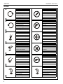
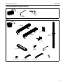
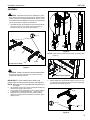
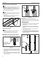
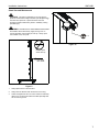
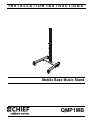
INSTALLATION INSTRUCTIONS
Mobile Base Music Stand
QMP1MB
Installation Instructions
QMP1MB
DISCLAIMER
Milestone AV Technologies and its affiliated corporations and
subsidiaries (collectively, "Milestone"), intend to make this
manual accurate and complete. However, Milestone makes no
claim that the information contained herein covers all details,
conditions or variations, nor does it provide for every possible
contingency in connection with the installation or use of this
product. The information contained in this document is subject
to change without notice or obligation of any kind. Milestone
makes no representation of warranty, expressed or implied,
regarding the information contained herein. Milestone assumes
no responsibility for accuracy, completeness or sufficiency of
the information contained in this document.
Chief® is a registered trademark of Milestone AV Technologies.
All rights reserved.
WARNING: Failure to read, thoroughly understand, and
follow all instructions can result in serious personal injury,
damage to equipment, or voiding of factory warranty! It is the
installer’s responsibility to make sure all components are
properly assembled and installed using the instructions
provided.
WARNING: Failure to provide adequate structural strength
for this component can result in serious personal injury or
damage to equipment! It is the installer’s responsibility to
make sure the structure to which this component is attached
can support five times the combined weight of all equipment.
Reinforce the structure as required before installing the
component.
WARNING: Exceeding the weight capacity can result in
IMPORTANT WARNINGS AND
CAUTIONS!
serious personal injury or damage to equipment! It is the
installer’s responsibility to make sure the combined weight of all
components on the stand does not exceed 150 lbs (68.04 kg).
WARNING: A WARNING alerts you to the possibility of
serious injury or death if you do not follow the instructions.
CAUTION: A CAUTION alerts you to the possibility of
damage or destruction of equipment if you do not follow the
corresponding instructions.
DIMENSIONS
DIMENSIONS: [MILLIMETERS]
INCHES
2
QMP1MB
Installation Instructions
LEGEND
3
Tighten Fastener
Pencil Mark
Apretar elemento de fijación
Marcar con lápiz
Befestigungsteil festziehen
Stiftmarkierung
Apertar fixador
Marcar com lápis
Serrare il fissaggio
Segno a matita
Bevestiging vastdraaien
Potloodmerkteken
Serrez les fixations
Marquage au crayon
Loosen Fastener
Drill Hole
Aflojar elemento de fijación
Perforar
Befestigungsteil lösen
Bohrloch
Desapertar fixador
Fazer furo
Allentare il fissaggio
Praticare un foro
Bevestiging losdraaien
Gat boren
Desserrez les fixations
Percez un trou
Phillips Screwdriver
Adjust
Destornillador Phillips
Ajustar
Kreuzschlitzschraubendreher
Einstellen
Chave de fendas Phillips
Ajustar
Cacciavite a stella
Regolare
Kruiskopschroevendraaier
Afstellen
Tournevis à pointe cruciforme
Ajuster
Open-Ended Wrench
Remove
Llave de boca
Quitar
Gabelschlüssel
Entfernen
Chave de bocas
Remover
Chiave a punte aperte
Rimuovere
Steeksleutel
Verwijderen
Clé à fourche
Retirez
By Hand
Optional
A mano
Opcional
Von Hand
Optional
Com a mão
Opcional
A mano
Opzionale
Met de hand
Optie
À la main
En option
Hex-Head Wrench
Security Wrench
Llave de cabeza hexagonal
Llave de seguridad
Sechskantschlüssel
Sicherheitsschlüssel
Chave de cabeça sextavada
Chave de segurança
Chiave esagonale
Chiave di sicurezza
Zeskantsleutel
Veiligheidssleutel
Clé à tête hexagonale
Clé de sécurité
Installation Instructions
QMP1MB
TOOLS REQUIRED FOR INSTALLATION
3/16"
(included)
PARTS
A (1)
[Left leg]
C (4)
[Snap-on cover]
B (1)
[Right leg]
E (1)
[Upright]
D (2)
[End cap]
G (1)
3/16"
[Drill bit]
F (1)
[Cross bracket]
J (4)
5/16-18 x 3/4"
K (4)
5/16-18 x 2-3/4"
L (4)
5/16-18 x 4-1/4"
H (1)
3/16"
M (4)
5/16"
4
Installation Instructions
QMP1MB
ASSEMBLY
inner column
CAUTION: Attachment holes may be damaged if a power
drill is used to insert button head cap screws. Screws should
first be inserted and turned BY HAND with the hex key or with
a handheld screwdriver BEFORE using the hex head drill bit
(G) and power drill to complete the attachment.
1.
Cable
Tie
Assemble two legs (A) and (B) to the stand cross bracket (F)
using two 5/16-18 x 4-1/4" button head cap screws (L)
through one end cap (D) per leg. (See Figure 1)
(L) x 4
(B)
Figure 2
(F)
NOTE: Insert and turn screws in order shown (1, 2, 3, 4). (See
Figure 3)
(Front view of stand)
(A)
(D) x 2
1
3
Figure 1
4
2
CAUTION: INNER COLUMN IS SHIPPED DISENGAGED
and may pinch hands! Hold both inner column and outer
upright while removing from box.
(Bottom view of stand)
Figure 3
IMPORTANT ! : Press cable tie tab to loosen and
remove cable tie from around knob post. (See Figure 2)
NOTE: Disengage knob on upright BEFORE attaching base to
2.
3.
4.
the upright.
Lift up slightly on the inner column of upright and hold firmly
toward top of upright. (See Figure 2)
Pull out knob on the upright and turn 90° in either direction
to disengage the locking mechanism. (See Figure 2)
Raise the inner column and turn the knob 90° in either
direction to engage the knob and lock the column in place.
(See Figure 2)
5.
Attach upright (E) to leg assembly using four 5/16-18 x 2-3/
4" button head cap screws (K) and four 5/16" washers (M).
(See Figure 3) and (See Figure 4)
(Front view of stand)
(E)
(K) x 4
(M) x 4
Figure 4
5
QMP1MB
Installation Instructions
Attaching Accessories to Mobile Stand
WARNING: EXCEEDING MAXIMUM WEIGHT CAPACITY
Inner
Column
Do NOT let
accessory
rest here
MAY LEAD TO SERIOUS PERSONAL INJURY OR
DAMAGE TO EQUIPMENT! It is the installer’s responsibility
to ensure the total amount of weight placed on the stand
does not exceed 150 lbs (68.04 kg).
3
2
CAUTION: Before attaching accessories to stand set the
brakes on the back wheels by pressing down on the tab.
(See Figure 5)
1.
Attach accessory and component(s) to stand following
instructions included with the accessory.
Figure 7
Press down to
set brakes
IMPORTANT ! : Set the height of the stand so the
accessories do NOT rest on the upper part of the outer column.
(See Figure 7) Always set the height so the knob is engaged in
a hole in the inner column.
Cable Management
1.
Signal cables can be run down the front flap of the upright
and out the front of the upright at any of the openings.
(See Figure 8)
2.
Any accessory power cords can be run through the front
and down through the upright to exit out the back. (See
Figure 8)
3.
Install the snap-on covers (C) to any opening that is not
being used. (See Figure 8)
4.
To remove the snap-on covers, grip the sides of the cover
in the middle and pull off. They can also be removed by
inserting a flat-blade screwdriver into the bottom slot and
rotating the screwdriver.
Figure 5
Adjusting Stand Height
CAUTION: ALWAYS remove components attached to
accessories BEFORE adjusting the height of stand.
1.
Firmly grasp top of inner column. (See Figure 6)
IMPORTANT ! : Firmly grasp at the top of the inner
column when adjusting stand height. (See Figure 6)
(Front view
of column)
2
(Rear view
of column)
1
Exits for
signal cables
Grasp top of inner
column (within shaded
area) when adjusting
stand height
Figure 6
2.
3.
6
3
(C)
Adjust the stand to the desired height by slightly lifting the
accessory, pulling out knob on the center post and turning
90o in either direction to disengage the locking mechanism.
(See Figure 7)
Raise or lower the upright, then turn the knob 90o either
direction to engage the knob and lock the stand at desired
height. (See Figure 7)
Exit for
power
cables
Figure 8
Installation Instructions
QMP1MB
Stand Use and Maintenance
CAUTION: This stand is intended for use only with the
products and maximum weight indicated (150 lbs [68.04 kg]).
Use with other products or products heavier than the
maximum weight indicated may result in instability causing
possible injury.
WARNING: STAND CAN TIP OVER RESULTING IN RISK
OF INJURY. Move stand slowly. Apply moving force on
narrow dimension. Never apply force at top - always push
near middle. Push, don’t pull.
x4
Figure 10
Do NOT push
stand near top
Push stand
near middle
Figure 9
1.
Always place stand on level surface.
2.
Always lock the wheels when the stand is not moving.
3.
Check and tighten the hex nuts on the casters occasionally.
(See Figure 10) These should be checked especially after
use on uneven ground.
7
QMP1MB
Installation Instructions
USA/International
Chief Manufacturing, a products division of Milestone AV Technologies
8809-002005 Rev00
2011 Milestone AV Technologies,
a Duchossois Group Company
www.chiefmfg.com
01/11
Europe
Asia Pacific
A
P
F
A
P
F
A
8401 Eagle Creek Parkway, Savage, MN 55378
800.582.6480 / 952.894.6280
877.894.6918 / 952.894.6918
Fellenoord 130 5611 ZB EINDHOVEN, The Netherlands
+31 (0)40 2668620
+31 (0)40 2668615
Office No. 1 on 12/F, Shatin Galleria
18-24 Shan Mei Street
Fotan, Shatin, Hong Kong
P 852 2145 4099
F 852 2145 4477