1
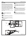
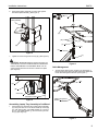
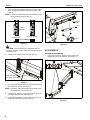
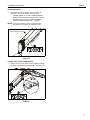
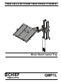
INSTALLATION INSTRUCTIONS
Instrucciones de instalación
Installationsanleitung
Instruções de Instalação
Istruzioni di installazione
Installatie-instructies
Instructions d´installation
Music Stand Laptop Tray
Spanish Product Description
German Product Description
Portuguese Product Description
Italian Product Description
Dutch Product Description
French Product Description
QMP1L
QMP1L
Installation Instructions
DISCLAIMER
Milestone AV Technologies, and its affiliated corporations and
subsidiaries (collectively, "Milestone"), intend to make this
manual accurate and complete. However, Milestone makes no
claim that the information contained herein covers all details,
conditions or variations, nor does it provide for every possible
contingency in connection with the installation or use of this
product. The information contained in this document is subject
to change without notice or obligation of any kind. Milestone
makes no representation of warranty, expressed or implied,
regarding the information contained herein. Milestone assumes
no responsibility for accuracy, completeness or sufficiency of
the information contained in this document.
Chief® is a registered trademark of Milestone AV Technologies.
All rights reserved.
WARNING: Failure to read, thoroughly understand, and
follow all instructions can result in serious personal injury,
damage to equipment, or voiding of factory warranty! It is the
installer’s responsibility to make sure all components are
properly assembled and installed using the instructions
provided.
WARNING: Failure to provide adequate structural strength
for this component can result in serious personal injury or
damage to equipment! It is the installer’s responsibility to
make sure the structure to which this component is attached
can support five times the combined weight of all equipment.
Reinforce the structure as required before installing the
component.
WARNING: Exceeding the weight capacity can result in
serious personal injury or damage to equipment! It is the
installer’s responsibility to make sure the combined weight of all
components and accessories does not exceed 15 lbs (6.8 kg).
IMPORTANT WARNINGS AND
CAUTIONS!
WARNING: A WARNING alerts you to the possibility of
serious injury or death if you do not follow the instructions.
CAUTION: A CAUTION alerts you to the possibility of
damage or destruction of equipment if you do not follow the
corresponding instructions.
DIMENSIONS
MAX 30.2
MIN 13.9
CLAMP FOR
INNER COLUMN
QTY 2
16.8
CLAMP FOR
OUTER COLUMN
QTY 2
8.4
11.9
14.0
6.9
13.9
4.0
DIMENSIONS: INCHES
2
Installation Instructions
QMP1L
LEGEND
Tighten Fastener
Phillips Screwdriver
Apretar elemento de fijación
Destornillador Phillips
Befestigungsteil festziehen
Kreuzschlitzschraubendreher
Apertar fixador
Chave de fendas Phillips
Serrare il fissaggio
Cacciavite a stella
Bevestiging vastdraaien
Kruiskopschroevendraaier
Serrez les fixations
Tournevis à pointe cruciforme
Loosen Fastener
Hex-Head Wrench
Aflojar elemento de fijación
Llave de cabeza hexagonal
Befestigungsteil lösen
Sechskantschlüssel
Desapertar fixador
Chave de cabeça sextavada
Allentare il fissaggio
Chiave esagonale
Bevestiging losdraaien
Zeskantsleutel
Desserrez les fixations
Clé à tête hexagonale
TOOLS REQUIRED FOR INSTALLATION
3/32" (included)
5/32" (included)
3/16" (included)
#2
PARTS
B (1)
[Bracket]
C (1)
[Height-adjust assembly]
A (1)
[Attachment plate]
F (2)
[Array clamp, outer]
E (2)
[Array clamp, inner]
L (4)
1/4-20 x 3/4"
T (1)
.094"
M (1)
5/16-18 x 3-1/2"
U (1)
.031
H (1)
[Pivot pin]
D (1)
[Laptop tray
assembly]
K (2)
#10
J (2)
10-24
G (1)
[Cable management cover]
N (1)
10-24 x 1/2"
P (2)
8-32 x 3/8"
Q (1)
3/32"
R (1)
5/32"
S (1)
3/16"
V (1)
5/16"
W (2)
.018"
3
QMP1L
Installation Instructions
ASSEMBLY AND INSTALLATION
Assembling Height-Adjust Arm to Cart/Stand
[Array clamp, inner shown]
1
(L) x 4
WARNING: IMPROPER INSTALLATION CAN LEAD TO
EQUIPMENT FALLING CAUSING SERIOUS PERSONAL
INJURY OR DAMAGE TO EQUIPMENT! DO NOT substitute
hardware! Use only hardware provided by manufacturer.
(E or F) x 2
WARNING: EXCEEDING MAXIMUM WEIGHT CAPACITY
MAY LEAD TO SERIOUS PERSONAL INJURY OR
DAMAGE TO EQUIPMENT! It is the user’s responsibility to
ensure the total amount of weight placed on the laptop stand
does not exceed 15 lbs (6.8 kg).
1.
Align bracket (B) with attachment plate (A), lining up rivet on
attachment plate with top mounting hole on bracket.
2.
Fasten bracket (B) to attachment plate (A) using one
10-24 x 1/2" Phillips undercut metal screw (N), two #10 flat
washers (K) and two 10-24 nylon locknuts (J). (See Figure 1)
(A)
1
QMP1FB or
QMP1MB
(N) x 1
Figure 2
5.
Insert top of height-adjust assembly (C) over lip on top of
attachment plate assembly. (See Figure 3)
(K) x 2
(C)
5
(B)
(J) x 2
Figure 1
3.
Choose appropriate array clamps to complete bracket
assembly to cart/stand.
•
•
4.
4
Array clamp, outer (F) is used to attach heightadjust assembly (C) to OUTER column of cart/
stand (below adjustment knob).
Array clamp, inner (E) is used to attach heightadjust assembly (C) to INNER column of cart/
stand (above adjustment knob).
Attach two array clamps (E or F) around cart/stand column to
attachment plate assembly using four 1/4-20 x 3/4" button
head cap screws (L). (See Figure 2)
Attachment
plate assembly
Figure 3
Installation Instructions
6.
QMP1L
Swing height-adjust assembly (C) down flush against
attachment plate assembly. (See Figure 4)
1
(M) x 1
Attachment
plate assembly
(D)
(W) x 2
(U)
6
(T)
(C)
(H)
(C)
Figure 4
(V)
7.
Tighten set screw using 5/32" hex key (R). (See Figure 5)
CAUTION: IMPROPER INSTALLATION CAN LEAD TO
ACCESSORY FALLING CAUSING SERIOUS PERSONAL
INJURY OR DAMAGE TO EQUIPMENT! Make sure set
screw engages back side of bracket on attachment plate.
(See Figure 5)
Figure 6
Cable Management
1.
Thread laptop cable through slot along the back edge of
laptop tray and down along the side of the height-adjust arm
to the cable management bracket. (See Figure 7)
Slot
(C)
1
(B)
Set screw
Cart/stand column
Figure 5
Cable management
bracket
Assembling Laptop Tray Assembly to Cart/Stand
1.
Attach laptop tray assembly (D) to height adjust assembly
(C) using one 5/16-18 x 3-1/2" button head cap screw (M),
two .018" spacers (W), one UHMW washer (U), one pivot
pin (H), one UHMW washer (T), and one 5/16" nylon lock
nut (V). (See Figure 6)
Figure 7
5
QMP1L
2.
Installation Instructions
Open the cable management bracket on the height-adjust
arm by sliding bracket towards the edge of the arm. (See
Figure 8)
(Cart/stand not shown)
NOTE: If necessary, cable management bracket attach screws
may be loosened using hex key (S).
Cable Path
(typical)
(G) x 1
Attach
Screws
CLOSED Position
OPEN Position
6
View from Bottom
Figure 8
(P) x 2
Figure 10
CAUTION: Ensure that adequate cable slack exists for
movement of laptop, and that cables will not be pinched when
bracket is closed.
3.
Carefully insert cables into bracket. (See Figure 9)
ADJUSTMENTS
Swing Arm Pivot/Swing
1.
Using 3/16" hex key (S), slightly loosen or tighten the
adjustment screw(s) as necessary. (See Figure 11)
Cable Path (typical)
1
Cable Management
Bracket (in open position)
Figure 9
4.
Close cable management bracket by sliding it back towards
the centerline of the arm. (See Figure 8)
NOTE: If necessary, cable management bracket attach screws
may be tightened using hex key (S).
5.
Carefully insert cables in cavity located in lower portion of
non-height adjustable arm. (See Figure 10)
6.
Install cable management cover (G) with two #8-32 x 3/8"
Phillips flat head screws (P). (See Figure 10)
Figure 11
6
Installation Instructions
QMP1L
Height Adjustable
1.
Using 5/32" hex key (R), slightly loosen or tighten the
adjustment screw as necessary. (See Figure 12)
•
•
If display settles on its own, rotate adjustment
screw counterclockwise (towards the "+" symbol).
If display rises on its own, rotate adjustment
screw clockwise (towards the "-" symbol).
NOTE: It may be necessary to raise or lower the height
adjustable arm to expose the adjustment screw.
Height adjustment screw
1
Figure 12
Laptop Tray Tension Adjustment
1.
Using 3/16" hex key (S), slightly loosen or tighten the laptop
tray tension adjustment screw as necessary. (See Figure 13)
1
Figure 13
7
QMP1L
Installation Instructions
USA/International
Europe
Chief Manufacturing, a products division
of Milestone AV Technologies
8832-002048 Rev00
2011 Milestone AV Technologies, a
Duchossois Group Company
www.chiefmfg.com
01/11
Asia Pacific
A
P
F
A
P
F
A
8401 Eagle Creek Parkway, Savage, MN 55378
800.582.6480 / 952.894.6280
877.894.6918 / 952.894.6918
Fellenoord 130 5611 ZB EINDHOVEN, The Netherlands
+31 (0)40 2668620
+31 (0)40 2668615
Office No. 1 on 12/F, Shatin Galleria
18-24 Shan Mei Street
Fotan, Shatin, Hong Kong
P 852 2145 4099
F 852 2145 4477