1
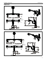
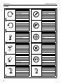
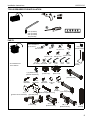
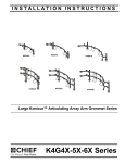
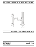
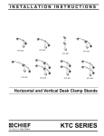
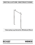
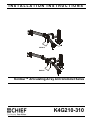
INSTALLATION INSTRUCTIONS
Istruzioni di installazione
Installatie-instructies
Instructions d´installation
Instrucciones de instalación
Installationsanleitung
Instruções de Instalação
K4G210
K4G310
Kontour™ Articulating Array Arm Grommet Series
Spanish Product Description
German Product Description
Portuguese Product Description
Italian Product Description
Dutch Product Description
French Product Description
K4G210-310
K4G210-310
Installation Instructions
DISCLAIMER
Milestone AV Technologies and its affiliated corporations and
subsidiaries (collectively “Milestone”), intend to make this
manual accurate and complete. However, Milestone makes no
claim that the information contained herein covers all details,
conditions or variations, nor does it provide for every possible
contingency in connection with the installation or use of this
product. The information contained in this document is subject
to change without notice or obligation of any kind. Milestone
makes no representation of warranty, expressed or implied,
regarding the information contained herein. Milestone assumes
no responsibility for accuracy, completeness or sufficiency of
the information contained in this document.
Chief® is a registered trademark of Milestone AV Technologies.
All rights reserved.
IMPORTANT SAFETY INSTRUCTIONS
WARNING: A WARNING alerts you to the possibility of
serious injury or death if you do not follow the instructions.
CAUTION: A CAUTION alerts you to the possibility of
damage or destruction of equipment if you do not follow the
corresponding instructions.
WARNING: Failure to read, thoroughly understand, and
follow all instructions can result in serious personal injury,
damage to equipment, or voiding of factory warranty! It is the
installer’s responsibility to make sure all components are
properly assembled and installed using the instructions
provided.
WARNING: Failure to provide adequate structural strength
for this component can result in serious personal injury or
damage to equipment! It is the installer’s responsibility to
make sure the structure to which this component is attached
can support five times the combined weight of all equipment.
Reinforce the structure as required before installing the
component.
WARNING: Exceeding the weight capacity can result in
serious personal injury or damage to equipment! It is the
installer’s responsibility to make sure the combined weight of
all components located on the K4G210-310 mounts up to
(and including) the display does not exceed 15 lbs (6.8 kg)
per display.
WARNING: Use this mounting system only for its intended
use as described in these instructions. Do not use
attachments not recommended by the manufacturer.
2
WARNING: Never operate this mounting system if it is
damaged. Return the mounting system to a service center for
examination and repair.
WARNING: Do not use this product outdoors.
--SAVE THESE INSTRUCTIONS--
Installation Instructions
K4G210-310
DIMENSIONS
K4G210
20° MAX
ANGLE
16.20
411.5
EXTENSION
37.13
943.2
MAX DISTANCE
TILT ADJUSTMENT
±12°
VESA
100 X 100
75 X 75
COMPATIBLE
INTERFACES
TILT ADJUSTMENT
±12°
15.28
388.2
+ 3.00 [76.2]
- 3.75 [95.3]
2.27
57.6
4.94
125.5
MAX
SURFACE
DEPTH
7.74
196.7
7.13
181.1
7.11
180.7
K4G310
20° MAX
ANGLE
24.12
612.7
16.20
411.5
EXTENSION
48.36
1228.4
MAX DISTANCE
TILT ADJUSTMENT
±12°
TILT ADJUSTMENT
±12°
TILT ADJUSTMENT
±12°
7.15
181.6
VESA
100 X 100
75 X 75
COMPATIBLE
INTERFACES
15.22
386.6
+ 3.00" [76.2]
- 3.75" [95.3]
13.34
338.8
2.27
57.6
7.74
196.7
4.94
125.5
MAX
SURFACE
DEPTH
7.11
180.7
3
K4G210-310
Installation Instructions
LEGEND
4
Tighten Fastener
Pencil Mark
Apretar elemento de fijación
Marcar con lápiz
Befestigungsteil festziehen
Stiftmarkierung
Apertar fixador
Marcar com lápis
Serrare il fissaggio
Segno a matita
Bevestiging vastdraaien
Potloodmerkteken
Serrez les fixations
Marquage au crayon
Loosen Fastener
Drill Hole
Aflojar elemento de fijación
Perforar
Befestigungsteil lösen
Bohrloch
Desapertar fixador
Fazer furo
Allentare il fissaggio
Praticare un foro
Bevestiging losdraaien
Gat boren
Desserrez les fixations
Percez un trou
Phillips Screwdriver
Adjust
Destornillador Phillips
Ajustar
Kreuzschlitzschraubendreher
Einstellen
Chave de fendas Phillips
Ajustar
Cacciavite a stella
Regolare
Kruiskopschroevendraaier
Afstellen
Tournevis à pointe cruciforme
Ajuster
Open-Ended Wrench
Remove
Llave de boca
Quitar
Gabelschlüssel
Entfernen
Chave de bocas
Remover
Chiave a punte aperte
Rimuovere
Steeksleutel
Verwijderen
Clé à fourche
Retirez
By Hand
Optional
A mano
Opcional
Von Hand
Optional
Com a mão
Opcional
A mano
Opzionale
Met de hand
Optie
À la main
En option
Hex-Head Wrench
Security Wrench
Llave de cabeza hexagonal
Llave de seguridad
Sechskantschlüssel
Sicherheitsschlüssel
Chave de cabeça sextavada
Chave de segurança
Chiave esagonale
Chiave di sicurezza
Zeskantsleutel
Veiligheidssleutel
Clé à tête hexagonale
Clé de sécurité
Installation Instructions
K4G210-310
TOOLS REQUIRED FOR INSTALLATION
1/2”
#2
5/16” (included)
3/16” (included)
5/32” (included)
1/8” (included)
PARTS
Hardware bag
(parts numbered on
bag as shown)
A1 (2)
3/8-16 x 2 3/4”
A2 (2)
3/8”
C (4)
1/4-20 x 1 1/4”
E2 (4)
F1 (1)
E1 (4)
[tie mount] #10-24 3/8” 1/8”
*8 for K4G210 and
12 for K4G310
J (2) (K4G310 only)
[channel attachment]
K (1)
[column cap]
B1 (2)
1/4-20 x 1/2”
D1 (2)
#10-32 x 1/2”
F2 (1)
3/16”
B2 (2)
1/4”
G (2)
[handle clamp]
D2 (2)
#10-32 x 3/8”
F3 (1)
5/16”
F4 (1)
5/32”
H (1)
[handle]
L (1)
[base cover]
X (1)
[left array arm]
M (8/12)*
M4x30mm
T (1)
[grommet screw and base]
N (8/12)*
M4x20mm
U (1)
[grommet plate]
P (8/12)*
M4x12mm
Q (8/12)*
3/8”
R (8/12)*
3/4”
W (6)
[bumper]
Y (1)
V (2)
[right array arm]
[cable management cover]
or
Z (1)
[column arm]
AA (1)
[K4G210 center]
BB (1)
[K4G310 center]
CC (1)
[column]
5
K4G210-310
Installation Instructions
Assembly And Installation
1.
Use four 1/4-20 x 1 1/4” flat head cap screws (C) to secure
grommet plate (U) to column (CC). Make sure longer legs of
grommet plate are aligned with the front of column. (See
Figure 1)
6.
Insert grommet screw (T) through grommet hole and thread
into center hole of grommet plate (U). (See Figure 3)
7.
Tighten grommet screw (T) until grommet base is tightened
against underside of desk and mount is securely mounted
to desk. (See Figure 3)
diameter between
1/2” and 3 1/2”
4
front of column
(CC)
1
(T)
7
(U)
(C) x 4
6
Figure 3
Figure 1
2.
5
Apply bumpers (W) to underside of grommet plate (U). (See
Figure 2)
8.
Carefully manipulate base cover (L) to create an opening
large enough to wrap cover around array column. (See
Figure 4)
9.
Wrap base cover (L) around column and slide it down until
base cover fits securely onto grommet plate (U). (See
Figure 4)
(U)
9
8
2 (W) x 6
Figure 2
3.
Locate a flat surface (thickness minimum of 1" to maximum
of 5") on which to mount the array assembly.
4.
If a hole doesn’t already exist, drill a hole in desk with a
diameter between 1/2” and 3 1/2” at desired mounting
location. (See Figure 3)
5.
Position mount on desk so that center hole of grommet plate
(U) is centered over grommet hole. (See Figure 3)
6
(L)
8
Figure 4
(U)
Installation Instructions
K4G210-310
10. Loosely install two 1/4-20 x 1/2” socket head carriage
screws (B1) through mounting holes on column arm (Z)
bracket and into 1/4” square nuts (B2). (See Figure 5)
(K4G210 shown)
(A1) x 2
14
11. Slide column arm (Z) bracket into column (CC) until desired
mounting height is reached. (See Figure 5)
(B2) x 2
11
(Z)
10
(A2) x 2
Figure 7
(B1) x 2
(CC)
15. Hang array center (AA or BB) onto column arm (Z)
faceplate. (See Figure 8)
(K4G210 shown)
(AA)
Figure 5
12. Tighten two 1/4-20 x 1/2” socket head carriage screws (B1)
to secure column arm (Z) at desired height. (See Figure 6)
(Z)
15
13. Install column cap (K) to column (CC). (See Figure 6)
faceplate
mounting
tab
12
(B1) x 2
13
(K)
(Z)
Figure 8
16. Use two #10-32 x 3/8” button head cap screws (D2) to
secure column arm (Z) to array center (AA or BB). (See
Figure 9)
Figure 6
14. Use two 3/8-16 x 2 3/4” socket head carriage screws (A1)
and two 3/8” lock nuts (A2) to secure left array arm (X) and
right array arm (Y) to array center (AA or BB). (See Figure 7)
7
K4G210-310
Installation Instructions
(K4G210 shown)
20. Use two #10-32 x 1/2” Phillips pan machine screws (D1)
and two handle clamps (G) to secure handle (H) to array
center (AA or BB). (See Figure 12)
(AA)
(K4G310 shown)
(Z)
(G) x 2
(D2) x 2
16
Figure 9
17. (K4G310 only) Insert two channel attachments (J) into back
of array center (BB). Attachments must be turned
horizontally in order to fit into channel. (See Figure 10)
NOTE: Channel attachments are already pre-installed on
(H)
20
(D1) x 2
K4G210. Proceed ahead to step 20 if installing
K4G210.
Figure 12
Display Installation
WARNING: Exceeding the weight capacity can result in
17
17
serious personal injury or damage to equipment! It is the
installer’s responsibility to make sure the combined weight of
all components located on the K4G210-310 Series mounts
up to (and including) the display does not exceed 15 lbs (6.8
kg) per display.
(J) x 2
CAUTION: Using screws of improper size may damage
Figure 10
18. (K4G310 only) Rotate channel attachments (J) 90°
clockwise. (See Figure 11)
19. (K4G310 only) Slide channel attachments (J) toward arm
assembly (Z) to prepare for handle installation. (See
Figure 11)
18
final position
19
18
19
Figure 11
8
your display! Proper screws will easily thread into display
mounting holes.
NOTE: Supplied screws (M, N and P) may not fit properly for
all displays. See display’s operating instructions for
details.
IMPORTANT ! : When applicable, always install center
display FIRST in order to prevent stand from tipping! If
there is no center faceplate (K4G210), be sure to support
opposite arm when mounting displays to prevent stand
from tipping! If possible, mount displays to both sides
simultaneously.
NOTE: Set height of center display prior to installing other
displays. See Height Adjustment Section for details.
Center of display must be at least 18" above desk
surface.
Installation Instructions
K4G210-310
Flush Mounting Holes
5.
1.
Position faceplate in desired mounting position. Adjust as
required before proceeding. See Height Adjustment Section
for details.
NOTE: If roll adjustment is desired for center faceplate, do not
Using Phillips screwdriver, carefully install two M4 x 12mm
Phillips pan machine screws (P) into the upper mounting
holes on the display. Thread screws completely into display,
then back out 3 complete turns. (See Figure 13)
6.
Repeat Steps 1-5 for other displays.
7.
Proceed to Cable Management Section.
2.
Tighten all four screws (P). Do not over-tighten!
tighten screws.
Recessed Mounting Holes
NOTE: If faceplate does not fit into recessed area of display,
2
proceed with the steps in this section.
(P) x 2
1.
Determine depth of recessed mounting holes relative to
back surface of display (against which faceplate will
contact).
2.
Select proper length spacer and screw from table below:
NOTE: All spacers used should be the same length. If the
recess depths result in multiple spacer lengths, then
select the longer spacer.
IF recess DEPTH is: THEN use spacer:
AND screw:
3/8” or less
Q (3/8” long)
N (M4 x 20mm)
More than 3/8” up to
and including 3/4”
R (3/4” long)
M (M4 x 30mm)
CAUTION: Using screws of improper size may damage
your display! Proper screws will easily and completely thread
into display mounting holes.
faceplate
(array arm not shown for clarity)
3.
Using Phillips screwdriver, carefully install two selected
screws (N or M) through selected spacers (Q or R) into the
upper mounting holes on the display. Thread screws
completely into display, then back out 3 complete turns.
(See Figure 15)
4.
Pick up and align display so that screws (N or M) (installed
on the back of the display in the previous step) fit into the
mounting holes on the faceplate. Lower the display firmly
into place. (See Figure 15)
Figure 13
3.
Pick up and align display so that screws (P) (installed on the
back of the display in the previous step) fit into the mounting
holes on the faceplate. Lower the display firmly into place.
(See Figure 13)
4. Using Phillips screwdriver, install two M4x12 mm
Phillips pan machine screws (P) through the lower
mounting holes on faceplate into the display. (See
Figure 14)
(N or M) x 2
3
(Q or R) x 2
4
4
faceplate
(array arm not shown for clarity)
Figure 14
(P) x 2
faceplate
(array arm not shown for clarity)
Figure 15
9
K4G210-310
5.
6.
Installation Instructions
Slide two remaining selected spacers (Q or R) in between
faceplate and display, positioning them over the lower two
mounting holes. (See Figure 16)
Install two remaining selected screws (N or M) through
lower two mounting holes on faceplate, selected spacers (Q
or R) into the lower mounting holes on the display. (See
Figure 16)
Pivot Adjustment (Column Arm)
1.
Use handle to extend or collapse column arm (Z) as
desired. (See Figure 18)
2.
(Optional) Loosen or tighten column arm pivot tension
screws as desired to increase or decrease pivot tension.
(See Figure 18)
(N or M) x 2
6
arm extended
faceplate
(array arm not
shown for clarity)
pivot tension
screws
(Q or R) x 2
Figure 16
7.
Tighten all four screws. Do not over-tighten!
arm collapsed
Adjustments
Figure 18
Pivot Adjustment (Array Arm)
1.
Array arms may pivot toward the front of mount up to 20° per
arm. (See Figure 17)
Height Adjustment
2.
When arms are at desired pivot position, lock pivot position
by tightening 3/8-16 x 2 3/4” socket head carriage screws
(A1) using 5/16” hex key (E5). (See Figure 17)
1.
Loosen 1/4-20 x 1/2” socket head carriage screws (B1)
holding column arm (Z) to column (CC). (See Figure 19)
2.
Adjust column arm to desired height. (See Figure 19)
3.
Tighten 1/4-20 x 1/2” socket head carriage screws (B1) to
lock column arm’s position. (See Figure 19)
2
(A1) x 2
1
3
2
Figure 17
Figure 19
10
Installation Instructions
K4G210-310
Faceplate Assembly Removal
Lateral Shift
1.
Remove hex head bolt from bottom of faceplate assembly.
(See Figure 20)
1.
Loosen knob on top of faceplate assembly until faceplate
can slide freely along array. (See Figure 22)
2.
Slide out removable plate from bottom of faceplate
assembly. (See Figure 20)
2.
Adjust lateral position as desired. (See Figure 22)
3.
Tighten knob to secure lateral position. (See Figure 22)
1
2
3
removable plate
3
2
2
1
2
Figure 20
3.
Remove faceplate assembly from array arm. (See Figure
20)
Figure 22
To Reattach Faceplate Assembly
Pitch/Roll/Yaw Adjustment
4.
Place faceplate assembly on array arm at desired mounting
position. (See Figure 21)
1.
Loosen knob on top of faceplate assembly. (See Figure 23)
5.
Slide removable plate back into slot at bottom of faceplate
assembly. (See Figure 21)
2.
Adjust pitch, roll and/or yaw as desired. (See Figure 23)
3.
6.
Reinstall hex head bolt removed in Step 1 to secure
faceplate assembly to array arm. (See Figure 21)
Tighten knob to secure desired faceplate position. (See
Figure 23)
1
3
4
2
5
Figure 23
removable plate
6
Figure 21
11
K4G210-310
Installation Instructions
Cable Management
3.
Route cables along mounting arms. (See Figure 26)
1.
Route cables from display through cable management
covers (V) as desired. (See Figure 24)
4.
Use cable ties (not included) to secure cables to tie clips
(E1). (See Figure 26)
2.
Install cable management covers (V) onto array arms (X
and Y). (See Figure 24)
NOTE: Leave enough slack in the cables so that arm may still
swing without resistance from the cables.
(K4G210 shown as example)
4 cable ties (not included)
2
1
cable
(example)
1
2
(V) x 2
1
Figure 26
Figure 24
Cable Management - Clips
1.
Use two #10-24 x 3/8” button head cap screws (E2) to
attach two tie mounts (E1) to upper mounting arm. (See
Figure 25)
2.
Use two #10-24 x 3/8” button head cap screws (E2) to
attach two tie mounts (E1) to lower mounting arm. (See
Figure 25)
1
(E2) x 2
(E1) x 2
(E1) x 2
2
Figure 25
12
(E2) x 2
Installation Instructions
K4G210-310
13
K4G210-310
14
Installation Instructions
Installation Instructions
K4G210-310
15
K4G210-310
Installation Instructions
USA/International
Europe
Chief Manufacturing, a products division
of Milestone AV Technologies
8800-002371 Rev02
2013 Milestone AV Technologies, a
Duchossois Group Company
www.chiefmfg.com
06/13
Asia Pacific
A
P
F
A
P
F
A
6436 City West Parkway, Eden Prairie, MN 55344
800.582.6480 / 952.225.6000
877.894.6918 / 952.894.6918
Franklinstraat 14, 6003 DK Weert, Netherlands
+31 (0) 495 580 852
+31 (0) 495 580 845
Office No. 1 on 12/F, Shatin Galleria
18-24 Shan Mei Street
Fotan, Shatin, Hong Kong
P 852 2145 4099
F 852 2145 4477