1
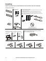
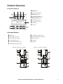
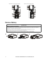
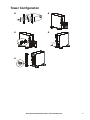
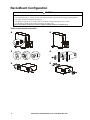
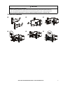
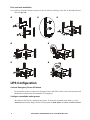
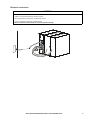
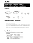
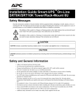
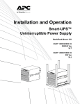
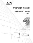
Installation Guide Smart-UPS™ X
2000/2200/3000 XL Tower/Rack-Mount 4U
Important Safety Messages
Read the instructions carefully to become familiar with the equipment before trying to install, operate,
service or maintain it. The following special messages may appear throughout this manual or on the
equipment to warn of potential hazards or to call attention to information that clarifies or simplifies a
procedure.
The addition of this symbol to a Caution product safety label indicates that a hazard exists that can result in
injury and product damage if the instructions are not followed.
The following safety messages may appear throughout this manual to warn of potential hazards.
CAUTION
CAUTION indicates a potentially hazardous situation which, if not avoided, can result in equipment damage and minor or
moderate injury.
CAUTION
CAUTION indicates a potentially hazardous situation which, if not avoided, can result in equipment damage.
Safety and General Information
Inspect the package contents upon receipt. Notify the carrier and dealer if there is any
damage.
Read the Safety Guide supplied with this unit before installing the UPS.
• Adhere to all local and national electrical codes.
• This UPS is intended for indoor use only.
• Do not operate this UPS in direct sunlight, in contact with fluids, or where there is excessive dust or
humidity.
• Be sure the air vents on the UPS are not blocked. Allow adequate space for proper ventilation.
• The battery typically lasts for two to five years. Environmental factors impact battery life. Elevated
ambient temperatures, poor quality utility power, and frequent short duration discharges will shorten
battery life.
• Connect the UPS power cable directly to a wall outlet. Do not use surge protectors or extension cords.
• The batteries are heavy. Remove the batteries prior to installing the UPS in a rack.
• Always install external battery packs (XLBPs) at the bottom of the rack. The UPS must be installed
above the XLBPs.
• The UPS display interface will recognize as many as 10 external battery packs connected to the UPS.
However there is no limit to the number of XLBPs that can be used with the UPS.
• Refer to Specifications in the Operation manual for UPS and battery weight.
Inventory
Inspect the contents upon receipt. Notify the carrier and dealer if the unit is damaged.
Included with all models
1 pair rail cleats
8 pan head screws
1 pair tower stabilizer brackets
Use 8 flat head screws to secure tower stabilizer brackets to the UPS
1 pair rack-mount brackets
Use 8 flat head screws to secure rack-mount brackets to the UPS
Use 4 ornamental screws to secure rack-mount brackets to the rails
Install a cage nut in the rack to secure the top hole of each rack-mount
bracket in a four post rack
(1) Documentation CD
(1) PowerChute software CD
Rack-mount support brackets and hardware
1 pair support
brackets
Two post racks
10 screws
Included with models that have factory installed
Network Management Cards
Four post racks
6 screws
6 washers
Included with High Voltage (HV) models
2
Smart-UPS X 2000/2200/3000 VA XL Tower/Rack-Mount 4U
Product Overview
Front panel features
1 Online LED
2 Power ON/OFF button
3 On Battery LED
4 Site Wiring Fault LED
5 Replace Battery LED
6 LCD display screen
APC by Schneider
Electric
7 UP/DOWN arrow keys
8 ENTER key
9 ESC key
su0343a
Rear panel features
1 SmartSlot
7 Controllable Outlet Group 3
2 Chassis ground screw
8 External battery pack connector
3 UPS utility power input
9 EPO connector
4 Circuit Breaker reset
: Serial port
5 Controllable Outlet Group 1
; USB port
6 Controllable Outlet Group 2
2000 VA, 120 Vac Low Voltage
3000 VA, 120 Vac Low Voltage
GROUP 2
GROUP 1
GROUP 3
su0756a
su0757a
Smart-UPS X 2000/2200/3000 VA XL Tower/Rack-Mount 4U
3
2200/3000 VA, 230 Vac High Voltage
3000 VA, 208 Vac High Voltage
GROUP 1
GROUP 1
GROUP 2
GROUP 3
GROUP 2
GROUP 3
su0754a
su0755a
Remove Battery
CAUTION
DAMAGE TO EQUIPMENT OR PERSONNEL
•
•
•
•
The equipment is heavy. Always practice safe lifting techniques adequate for the weight of the equipment.
The UPS + the battery weighs 41 kg (90.4 lb).
The battery weighs 23.8 kg (52.4 lb). Remove the battery before installing the unit in a rack.
Use the battery handle to lift and slide the battery out of the UPS.
Failure to follow these instructions can result in equipment damage and minor or moderate injury
4
Smart-UPS X 2000/2200/3000 VA XL Tower/Rack-Mount 4U
su0760a
3
su0759a
2
su0758a
1
Tower Configuration
2
su0761a
1
s u07
4
su0774a
3
63a
s u07
6 4a
su0762a
5
Smart-UPS X 2000/2200/3000 VA XL Tower/Rack-Mount 4U
5
Rack-Mount Configuration
CAUTION
DAMAGE TO EQUIPMENT OR PERSONNEL
•
•
•
•
The equipment is heavy. Always practice safe lifting techniques adequate for the weight of the equipment.
The UPS + the battery weighs 41 kg (90.4 lb).
The battery weighs 23.8 kg (52.4 lb). Remove the battery before installing the unit in a rack.
Use the battery handle to lift and slide the battery out of the UPS.
Failure to follow these instructions can result in equipment damage and minor or moderate injury
Tower to rack-mount conversion
1
2
s u07
s u 07
64b
4
5
su0761b
su0583b
3
63b
6
su0766a
s u0 7
6
Smart-UPS X 2000/2200/3000 VA XL Tower/Rack-Mount 4U
69a
CAUTION
DAMAGE TO EQUIPMENT OR PERSONNEL
• When installing equipment in a rack, always install external battery packs at the bottom of the rack.
• The UPS should always be installed above the external battery packs in rack or stack configurations.
Failure to follow these instructions can result in equipment damage and minor or moderate injury
Two post rack installation
1
2
3
s u07
70a
68a
su0776a
s u07
5
6
Smart-UPS X 2000/2200/3000 VA XL Tower/Rack-Mount 4U
su0772a
su0771a
su0773a
4
7
Four post rack installation
Use an APC by Schneider Electric four post rail kit. To order the rail kit go to the APC by Schneider Electric
Web site apc.com.
1
2
3
su0777a
78a
su07
4
5
su07
79a
su 07
6
80a
7
81a
su0782a
su07
UPS Configuration
Connect Emergency Power Off feature
For instructions on how to connect the Emergency Power Off (EPO) switch, refer to the Operation and
Maintenance manual on the Documentation CD (supplied).
Configure controllable outlet groups
The outlets on the UPS are configured into groups. To utilize the controlled outlet features, use the
Advanced menus on the display interface and navigate to: Main Menu > Control > Outlet1 Control.
8
Smart-UPS X 2000/2200/3000 VA XL Tower/Rack-Mount 4U
Electrical connections
CAUTION
RISK OF EQUIPMENT DAMAGE
• Adhere to all local and national electrical codes.
• Wiring should be performed by qualified electrician.
• Always connect the UPS to a grounded outlet.
Failure to follow these instructions can result in equipment damage
U PS
su0788a
vice
i c De
n
e
o
tr
D e v ic
E le c
ronic
t
c
le
E
Smart-UPS X 2000/2200/3000 VA XL Tower/Rack-Mount 4U
9
Select models are ENERGY STAR® qualified.
For more information go to www.apc.com/site/recycle/index.cfm/energy-efficiency/energy-star/
© 2013 APC by Schneider Electric. APC, the APC logo, Smart-UPS and PowerChute are owned by
Schneider Electric Industries S.A.S., or their affiliated companies. All other trademarks are property of
their respective owners.
EN 990-4651A-002
03/2013