1
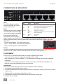
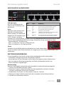
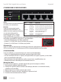
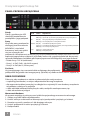
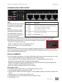
8-PORT
PoE DESKTOP
GIGABIT SWITCH
USER MANUAL
MODEL 560641
intellinet-network.com
INT-560641-UM-ML1-0812-02
PoE Desktop Gigabit Switch English
CONNECTIONS & INDICATORS
LEDs
The LED indicators make it
easier to monitor the switch
and its connections.
LED StatusOperation
Power
On
Off
Power on
Check the AC connection; turn the power on
PoE
On
Port is linked to a PSE/PoE device
Off
No PSE/PoE device is linked
Ports
Valid port connection
All ports on the switch support Link/Act On
Blinking
Valid port connection; data transmitted/received
Auto-MDI/MDI-X functionality, Off
No link established
so crossover cables and uplink
Loop
Blinking
A loop exists
ports are not needed for
Off
No loop
connections to PCs, routers,
other switches, etc. Cat5/5e/6 UTP/STP cables provide optimal performance; if a status LED
doesn’t indicate a link or activity, check the corresponding device for proper setup and
operation.
ON
100-240 VAC
• Power consumption: 135 watts (maximum)
• Ports 1-4: PoE / PoE+ (up to 34 watts per port)
• Ports 5-8: PoE (up to 15.4 watts per port)
OFF 50/60 Hz 2A max.
Power
Use the included power cord to connect the device (next to the On/Off switch on the rear
panel) to an AC outlet. Confirm that the power LED on the front panel is lit.
PLACEMENT
Prior to use, it is recommended that the switch be placed/positioned:
• on a level surface that can support the weight of the switch
• with a minimum of 25 mm (approx. 1”) of clearance on the top and sides for adequate
ventilation
• away from sources of electrical noise: radios, transmitters, broadband amplifiers, etc.
• where it cannot be affected by excessive moisture
Rackmount
The switch includes brackets and screws for optional rack mounting.
1. Disconnect any cables from the switch.
2. Position a bracket over the mounting holes on one side of the switch and secure it in place
with screws.
3 Repeat Step 2 on the other side of the switch.
4. Position the switch in the rack and screw the brackets to the rack.
5. Reconnect any cables.
2
ENGLISH
PoE Desktop Gigabit Switch Deutsch
ANSCHLÜSSE & ANZEIGEN
LED-Anzeigen
Die LEDs vereinfachen das
Ablesen der Funktionen und
Anschlüsse.
LED StatusBedeutung
Power
An
Aus
Gerät wird mit Strom versorgt
Stromanschluss prüfen/Gerät einschalten
PoE
An
Port ist mit PSE/PoE-Gerät verbunden
Aus
Kein PSE/PoE-Gerät angeschlossen
Ports
Link/Act
An
Verbindung ist hergestellt
Alle Ports unterstützen Auto
Blinkend
Verbindung ist hergestellt; Datenübertragung
MDI/MDI-X Funktionalität,
Aus
Verbindung ist nicht hergestellt
daher werden Crosskabel und
Loop
Blinkend
Eine illegale Endlosschleiße wurde entdeckt
Uplink-Ports für Verbindungen
Aus
Es wurden keine Endlosschleißen entdeckt
zu PCs, Routern, anderen
Switchen, etc. nicht benötigt. Cat5/5e- UTP/STP-Kabel bieten die beste Performance. Wenn
eine LED keine Verbindung/Aktivität anzeigt, überprüfen Sie das verbundene Gerät.
• Stromverbrauch: 135 Watt (max.)
ON
• Ports 1-4: PoE / PoE+ (bis zu 34 Watt pro Port)
• Ports 5-8: PoE (bis zu 15,4 Watt pro Port)
Strom
OFF
Schließen Sie das beiliegende Stromkabel an das Gerät (neben dem
An/Aus-Schalter) und an eine Steckdose an. Vergewissern Sie sich dass die “Power”-LED
aufleuchtet.
NUTZUNGSUMGEBUNG
Er wird empfohlen, den Switch vor der Nutzung folgendermaßen aufzustellen:
• auf ebenem Untergrund, der das Gewicht des Switches
• mit mindestens 25 mm Abstand zu allen Seiten für angemessenen Luftdurchsatz
• fern von anderen Übertragungsgeräten wie Radios, Breitbandverstärker, etc.
• nicht in feuchten Umgebungen
Rackmontage
Diesem Switch liegen Haltewinkel und Schrauben für optionale Rackmontage bei.
1. Trennen Sie alle Kabel von dem Switch.
2. Platzieren Sie einen Haltewinkel über den Montagelöchern auf einer Seite des
Switches und fixieren Sie ihn mit Schrauben.
3. Wiederholen Sie Schritt 2 auf der anderen Seite des Switches.
4. Platzieren Sie den Switch in dem Rack und schrauben Sie die Haltewinkel fest.
5. Schließen Sie alle Kabel wieder an.
DEUTSCH
3
Switch PoE Gigabit de escritorio
Español
CONEXIONES E INDICADORES
LEDs
Los LEDs hacen mas facil monitorear
el switch y sus conexiones.
LED StatusOperación
Power
EncendidoEncendido
Apagado
Revise la conexión AC; encienda de nuevo
PoE
Encendido Puerto vinculado a un dispositivo PSE/PoE
Puertos
Apagado
No hay un dispositivo PSE/PoE conectado
Todos los puertos del switch
Link/Act
Encendido Valide el puerto de conexión
soportan Auto-MDI/MDI-X , los
Parpadeo
Datos trasmitidos/recibidos
cables crossover y puertos de enlace Apagado
No hay comunicación
no son necesarios para las
Loop
Parpadeo
Existe redundancia
conexiones para PCs, routers,
Apagado
Sin redundancia
otros switches, etc. los cables
Cat5/5e UTP/STP proporcionan un redimiento optimo; Si un LED no indica conectividad ó
actividad, compruebe las conexiones sean adecuadas.
ON
• Consumo de potencia: 135 Watts (máximo)
• Puertos 1 a 4: PoE/ PoE+ (hasta 34 Watts por puerto)
• Puertos 5 a 8: PoE (hasta 15.4 Watts por puerto)
OFF
Alimentación
Utilice el cable de alimentación incluido para conectar el dispositivo (junto al switch On /
Off) a una toma de CA. Confirme que el LED en el panel frontal está encendido.
COLOCACIÓN
Antes de utilizarlo, se recomienda que el switch sea ubicado/fijado:
• sobre una superficie plana que pueda soportar el peso del switch
• con un mínimo de 25 mm (1” aprox.) de espacio libre en la parte superior y en los lados
para una ventilación adecuada
• lejos de fuentes de ruido eléctrico: radios, transmisores, amplificadores, etc.
• donde puede verse afectado por la humedad excesiva
Montaje en Rack
El switch incluye soportes y tornillos opcionales para el montaje en el Rack.
1. Desconecte cualquier cable del switch.
2. Coloque el soporte sobre los orificios de montaje, ubicados a un lado del switch y
sujételo con los tornillos.
3. Repita el paso 2 en el lado contrario del switch.
4. Coloque el switch en el rack y atornille los soportes al rack.
5. Conecte nuevamente todos los cables.
4
ESPAÑOL
Commutateur Gigabit en boîtier externe PoE
Français
CONNEXIONS & INDICATEURS
Les DEL
Les voyants d’état simplifient lire
les fonctions et les connexions.
LED StatusOperation
Power
Allumé
Éteint
Appareil est alimenté
Vérifiez l’alimentation/Allumez l’appareil
PoE
Allumé
Port est connecté à un appareil PSE/PoE
Les ports
Éteint
Port n’est connecté pas à un appareil PSE/PoE
Tous les ports de ce
Link/Act
Allumé
Connexion est établie
commutateur prennent en
Clignotant Connexion est établie; données sont transmises
charge la fonctionnalité Auto
Éteint
Connexion n’est pas établie
MDI/MDI-X, donc des câbles
Loop
Clignotant Boucle existe
croisés et des liaisons montantes Off
Boucle n’est pas existe
ne sont pas nécessaires pour des
connections aux PC, routeurs, etc. Des câbles Cat5/5e UTP/STP garantissent des performances
optimales; si un DEL n’indique pas d’activité, vérifiez l’appareil correspondant.
• Consommation : 135 watts (maximum)
ON
• Ports 1-4 : PoE/PoE+ (jusqu’à 34 watts par port)
• Ports 5-8 : PoE (jusqu’à 15,4 watts par port)
Alimentation
OFF
Connectez le cordon d’alimentation à l’appareil (à côté de
l’ interrupteur du réseau) et à une prise de courant. Vérifiez que le DEL “Power” sur le panneau
avant est allumé.
PLACEMENT
Avant d’utiliser le commutateur, il est recommandé de le placer:
• sur une surface plane qui peut supporter son poids
• ac. un écartement minimal de 25 mm d’autres objets pour une ventilation suffisante
• loin des appareils électriques qui peuvent être source d‘interférence (des radios etc.)
• loin des environnements humides
Montage en rack
Le commutateur inclut des équerres et vis pour un montage en rack optionnelle.
1. Déconnectez tous les cordons du commutateur.
2. Positionnez une équerre sur les trous de montage à un côté du commutateur et
sécurisez-la avec des vis.
3. Répétez l’étape 2 à l’autre côté du commutateur.
4. Positionnez le commutateur en rack et vissez les équerres au rack.
5. Reconnectez tous les cordons.
FRANÇAIS
5
Przełącznik Gigabit Desktop PoE
Polski
PANEL PRZEDNI URZĄDZENIA
Diody
Diody sygnalizacyjne LED
ułatwiają monitorowanie
przełącznika i jego połączeń.
DiodaStatusObjaśnienie
Power
On (wł.) Urządzenie włączone
Off (wył.) Sprawdź, czy zasilanie jest podłączone; włącz urządzenie
PoE
On (wł.)
Port jest połączony z urządzeniem PoE
Off (wył.) Nie ma połączenia z urządzeniem PoE
Porty
Wszystkie porty przełącznika Link/Act On (wł.) Prawidłowe podłączenie portu
Migająca Prawidłowe podłączenie portu; transmisja/odbiór pakietów
obsługują auto-krosowanie Off (wył.) Nie nawiązano połączenia
MDI/MDI-X, więc kabel
Loop
Migająca Istnieje połączenie
krosowany oraz port uplink Off (wył.) Brak połączenia
nie jest wymagany do
połączenia z komputerami, routerami, czy innymi przełącznikami. Kable Cat5/5e/6 UTP/STP
zapewniają optymalną wydajność; jeśli diody statusu nie sygnalizują linku lub aktywności,
sprawdź podłączone urządzenie pod kątem poprawności konfiguracji oraz jego zasilania.
• Pobór mocy: 135 W (maximum)
ON
• Porty 1-4: PoE / PoE+ (do 34 W na port)
• Porty 5-8: PoE (do 15,4 W na port)
Zasilanie
OFF
Użyj znajdującego się w zestawie kabla zasilającego do podłączenia
przełącznika do gniazda sieci energetycznej. Sprawdź, czy dioda zasilania (Power) zapaliła się.
UMIEJSCOWIENIE
Zaleca się, aby urządzenie w trakcie użytkowania było umiejscowione:
•na płaskiej powierzchni, w miejscu odpowiednim do wagi urządzenia
•dla zapewnienia dobrej wentylacji w odległości co najmniej 25 mm obudowy urządzenia
od podłoża, na którym się znajduje
•z dala od źródeł zakłóceń elektrycznych: radia, nadajniki szerokopasmowe, itp.
•z dala od nadmiernej wilgoci
Mocowanie Rackowe
W zestawie znajdują się uchwyty oraz śrubki do opcjonalnego mocowania rackowego.
1. Odłącz wszystkie kable od przełącznika.
2. Umieść uchwyt na dziurach na bocznej części przełącznika i przykręć go śrubami.
3. Powtórz czynność z punktu nr 2 dla drugiego uchwytu.
4. Umieść przełącznik w racku i przykręć go śrubami.
5. Podłącz kable.
6
POLSKI
Switch Gigabit PoE Desktop
Italiano
CONNESSIONI E INDICATORI
LEDs
Gli indicatori LED permettono
di monitorare facilmente lo
switch e le sue connessioni.
LEDStato
Operazione
PWR Acceso
Spento
Acceso
Verificare la connessione AC; accendere l’apparecchio
PoE Acceso
Porta collegata alla periferica PSE/PoE
Spento
Nessuna periferica PSE/PoE è collegata
Porte
LNK/ Acceso
Porta di connessione valida
Tutte le porte dello switch
ACT Lampeggiante Porta di connessione valida; trasmissione/ricevimento dati
supportano la funzionalità
Spento
Nessuna connessione stabilita
Auto-MDI/MDI-X, così cavi
Loop Lampeggiante Errore di loop
incrociati e porte uplink non Spento
Nessun errore di loop
sono necessarie per
connessioni a PC, router, altri switch, etc. I cavi Cat5/5e/6 UTP/STP forniscono ottimali
prestazioni; se il LED di stato non indica una connessione o un’attività, verificare la
corrispondente periferica per un corretto settaggio e funzionamento.
ON
• Consumo: 135 watt (massimo)
• Porte 1-4: PoE / PoE+ (fino a 34 watt per porta)
• Porte 5-8: PoE (fino a 15.4 watt per porta)
OFF
Alimentazione
Utilizzare il cavo di alimentazione per collegare l’apparecchiatura (vicino all’interruttore
posto sul pannello posteriore) alla presa di corrente AC. Verificare che il LED di alimentazione
sul pannello frontale è illuminato.
COLLOCAMENTO
Prima di utilizzare il prodotto, si consiglia di fare attenzione a dove viene posizionato lo switch:
•su una superficie piana che può supportare il peso dello switch
• con un minimo di 25 mm (approssimativamente 1”) di spazio libero verso l’alto e
lateralmente per permettere un’adeguata ventilazione
• lontano da sorgenti che possono provocare disturbi e interferenze elettromagnetiche:
radio, trasmettitori, amplificatori di banda, ecc.
• dove non venga sottoposto ad eccessiva umidità
Montaggio a rack
Lo switch include staffe e viti per il montaggio opzionale a rack.
1. Disconnettere qualsiasi cavo dallo switch.
2. Posizionare la staffa sui fori di fissaggio su un lato dello switch e assicurarla sul posto con
le viti.
3. Ripetere il passo 2 sull’altro lato dello switch.
4. Posizionare lo switch sul rack ed avvitare le staffe sul rack.
5. Recollegare i cavi.
ITALIANO
7
WASTE ELECTRICAL & ELECTRONIC EQUIPMENT
Disposal of Electric and Electronic Equipment (applicable in the European Union and other
European countries with separate collection systems)
ENGLISH
This symbol on the product or its packaging indicates that this product shall not be treated as household waste. Instead, it should be taken to an applicable collection point for the recycling of electrical and
electronic equipment. By ensuring this product is disposed of correctly, you will help prevent
potential negative consequences to the environment and human health, which could otherwise
be caused by inappropriate waste handling of this product. If your equipment contains easily
removable batteries or accumulators, dispose of these separately according to your local
requirements. The recycling of materials will help to conserve natural resources. For more
detailed information about recycling of this product, contact your local city office, your household waste
disposal service or the shop where you purchased this product. In countries outside of the EU: If you wish to
discard this product, contact your local authorities and ask for the correct manner of disposal.
DEUTSCH
Dieses auf dem Produkt oder der Verpackung angebrachte Symbol zeigt an, dass dieses Produkt nicht mit
dem Hausmüll entsorgt werden darf. In Übereinstimmung mit der Richtlinie 2002/96/EG des Europäischen
Parlaments und des Rates über Elektro- und Elektronik-Altgeräte (WEEE) darf dieses Elektrogerät nicht im
normalen Hausmüll oder dem Gelben Sack entsorgt werden. Wenn Sie dieses Produkt entsorgen möchten,
bringen Sie es bitte zur Verkaufsstelle zurück oder zum Recycling-Sammelpunkt Ihrer Gemeinde.
ESPAÑOL
Este símbolo en el producto o su embalaje indica que el producto no debe tratarse como residuo doméstico.
De conformidad con la Directiva 2002/96/CE de la UE sobre residuos de aparatos eléctricos y electrónicos
(RAEE), este producto eléctrico no puede desecharse con el resto de residuos no clasificados. Deshágase
de este producto devolviéndolo a su punto de venta o a un punto de recolección municipal para su reciclaje.
FRANÇAIS
Ce symbole sur Ie produit ou son emballage signifie que ce produit ne doit pas être traité comme un
déchet ménager. Conformément à la Directive 2002/96/EC sur les déchets d’équipements électriques et
électroniques (DEEE), ce produit électrique ne doit en aucun cas être mis au rebut sous forme de déchet
municipal non trié. Veuillez vous débarrasser de ce produit en Ie renvoyant à son point de vente ou au
point de ramassage local dans votre municipalité, à des fins de recyclage.
POLSKI
Jeśli na produkcie lub jego opakowaniu umieszczono ten symbol, wówczas w czasie utylizacji nie wolno
wyrzucać tego produktu wraz z odpadami komunalnymi. Zgodnie z Dyrektywą Nr 2002/96/WE w sprawie
zużytego sprzętu elektrycznego i elektronicznego (WEEE), niniejszego produktu elektrycznego nie wolno usuwać jako nie posortowanego odpadu komunalnego. Prosimy o usuniecie niniejszego produktu
poprzez jego zwrot do punktu zakupu lub oddanie do miejscowego komunalnego punktu zbiórki
odpadów przeznaczonych do recyklingu.
ITALIANO
Questo simbolo sui prodotto o sulla relativa confezione indica che il prodotto non va trattato come un rifiuto
domestico. In ottemperanza alla Direttiva UE 2002/96/EC sui rifiuti di apparecchiature elettriche ed
elettroniche (RAEE), questa prodotto elettrico non deve essere smaltito come rifiuto municipale misto.
Si prega di smaltire il prodotto riportandolo al punto vendita o al punto di raccolta municipale locale per
un opportuno riciclaggio.
8
REGULATORY STATEMENTS
FCC Class B
This equipment has been tested and found to comply with the limits for a Class B digital device, pursuant to Part 15 of Federal Communications Commission (FCC) Rules. These limits are designed to provide
reasonable protection against harmful interference in a residential installation. This equipment generates, uses and can radiate radio frequency energy, and if not installed and used in accordance with the
instructions may cause harmful interference to radio communications. However, there is no guarantee
that interference will not occur in a particular installation. If this equipment does cause harmful interference to radio or television reception, which can be determined by turning the equipment off and on,
the user is encouraged to try to correct the interference by one or more of the following measures: reorient or relocate the receiving antenna; increase the separation between the equipment and the receiver;
connect the equipment to an outlet on a circuit different from the receiver; or consult the dealer or an
experienced radio/TV technician for help.
CE / R&TTE
English: This device complies with the requirements of R&TTE Directive 1999/5/EC.
The Declaration of Conformity for this product is available at:
Deutsch: Dieses Gerät enspricht der Direktive R&TTE Direktive 1999/5/EC.
Die Konformitätserklärung für dieses Produkt finden Sie unter::
Español: Este dispositivo cumple con los requerimientos de la Directiva R&TTE 1999/5/EC.
La declaración de conformidad para este producto esta disponible en:
Français: Cet appareil satisfait aux exigences de la directive R&TTE 1999/5/CE.
La Déclaration de Conformité pour ce produit est disponible à l’adresse :
Polski: Urządzenie spełnia wymagania dyrektywy R&TTE 1999/5/EC.
Deklaracja zgodności dostępna jest na stronie internetowej producenta:
Italiano: Questo dispositivo è conforme alla Direttiva 1999/5/EC R&TTE.
La dichiarazione di conformità per questo prodotto è disponibile al:
intellinet-network.com
9
WARRANTY INFORMATION
ENGLISH: For warranty information, go to intellinet-network.com/warranty.
DEUTSCH: Garantieinformationen finden Sie hier unter intellinet-network.com/warranty.
ESPAÑOL: Si desea obtener información sobre la garantía, visite intellinet-network.com/warranty.
FRANÇAIS: Pour consulter les informations sur la garantie, rendezvous à l’adresse
intellinet-network.com/warranty.
POLSKI: Informacje dotyczące gwarancji znajdują się na stronie intellinet-network.com/warranty.
ITALIANO: Per informazioni sulla garanzia, accedere a intellinet-network.com/warranty.
En México: Póliza de Garantía Intellinet — Datos del importador y responsable ante el consumidor
IC Intracom México, S.A. de C.V. • Av. Interceptor Poniente # 73, Col. Parque Industrial La Joya, Cuautitlán
Izcalli, Estado de México, C.P. 54730, México. • Tel. (55)1500-4500
La presente garantía cubre este producto por 3 años contra cualquier defecto de fabricación en sus materiales y mano de obra, bajo las siguientes condiciones:
1. Todos los productos a que se refiere esta garantía, ampara su cambio físico, sin ningún cargo para
el consumidor.
2. El comercializador no tiene talleres de servicio, debido a que los productos que se garantizan no
cuentan con reparaciones, ni refacciones, ya que su garantía es de cambio físico.
3. La garantía cubre exclusivamente aquellas partes, equipos o sub-ensambles que hayan sido instaladas
de fábrica y no incluye en ningún caso el equipo adicional o cualesquiera que hayan sido adicionados
al mismo por el usuario o distribuidor.
Para hacer efectiva esta garantía bastará con presentar el producto al distribuidor en el domicilio donde
fue adquirido o en el domicilio de IC Intracom México, S.A. de C.V., junto con los accesorios contenidos
en su empaque, acompañado de su póliza debidamente llenada y sellada por la casa vendedora
(indispensable el sello y fecha de compra) donde lo adquirió, o bien, la factura o ticket de compra
original donde se mencione claramente el modelo, número de serie (cuando aplique) y fecha de
adquisición. Esta garantía no es válida en los siguientes casos: Si el producto se hubiese utilizado en
condiciones distintas a las normales; si el producto no ha sido operado conforme a los instructivos de
uso; o si el producto ha sido alterado o tratado de ser reparado por el consumidor o terceras personas.
ENGLISH: For specifications, go to intellinet-network.com.
DEUTSCH: Die Spezifikationen finden Sie auf intellinet-network.com.
ESPAÑOL: Para más especificaciones, visite intellinet-network.com.
FRANÇAIS: Vous trouvez les spécifications sur intellinet-network.com.
POLSKI: Pełną specyfikację produktu znajdziecie Państwo na stronie intellinet-network.com.
ITALIANO: Per ulteriori specifiche, visita il sito intellinet-network.com.
North & South America
IC Intracom Americas
550 Commerce Blvd.
Oldsmar, FL 34677
USA
Asia & Africa
IC Intracom Asia
Far Eastern Technology Center
7-F No. 125, Section 2, Da Tong Rd.
Shijr, Taipei
Taiwan, ROC
Europe
IC Intracom Europe
Löhbacher Str. 7
D-58553 Halver
Germany
All trademarks and trade names are the property of their respective owners.
Alle Marken und Markennamen sind Eigentum Ihrer jeweiligen Inhaber.
Todas las marcas y nombres comerciales son propiedad de sus respectivos dueños.
Toutes les marques et noms commerciaux sont la propriété de leurs propriétaires respectifs.
Wszystkie znaki towarowe i nazwy handlowe należą do ich właścicieli.
Tutti i marchi registrati e le dominazioni commerciali sono di proprietà dei loro rispettivi proprietari.
10
© IC Intracom. All rights reserved.
Intellinet and Manhattan are trademarks of IC Intracom, registered in the U.S. and other countries.