1
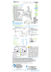
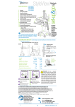
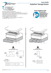
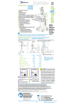
User Guide
StyleView® SV40
Electronic Medical Records (EMR) Cart
with LCD Mount
For the latest User Installation Guide and StyleLink Software Download please visit:
Encontrará la versión más reciente del manual de instalación del usuario y el software de StyleLink en:
Si vous souhaitez télécharger le dernier manuel d’installation de l’utilisateur ou le logiciel StyleLink, rendez-vous sur :
Den neuesten Installationsleitfaden für Benutzer sowie den neuesten StyleLink-Softwaredownload finden Sie unter:
Voor de nieuwste Installatiehandleiding voor de gebruiker en voor het downloaden van StyleLink-software gaat u naar:
Per scaricare le versioni più recenti del manuale di installazione e del software StyleLink, andare al sito:
De senaste versionerna av installationshandledningen och nedladdning av programvaran för StyleLink finns på:
最新版ユーザインストールガイドとスタイルリンク ソフトウェアは次のサイトでダウンロードできます。
请从下列地址获取最新版本的用户安装指南和 StyleLink 软件下载:
사용자 설치 안내서 및 StyleLink 소프트웨어 다운로드는 다음 웹 사이트에서 제공하고 있습니다.
www.ergotron.com
User's Guide - English
Guía del usuario - Español
Manuel de l’utilisateur - Français
Gebruikersgids - Nederlands
Benutzerhandbuch - Deutsch
Guida per l’utente - Italiano
Användarhandbok - svenska
ユーザーガイド : 日本語
用户指南 : 汉语
A
IMPORTANT! This product will need tension adjustments once installation is complete.
Make sure all equipment is properly installed on the product before attempting range
of motion or tension adjustments. Any time equipment is added or changed on this
product resulting in a different mounted weight, you should repeat the adjustment
steps to ensure safe and optimum operation. This product should move smoothly and
easily through the full range of motion and stay where you set it. If movement is difficult
or the product does not stay where you set it, follow the adjustment instructions to
loosen or tighten the tension to create a smooth, easy motion. Depending on your
product and the adjustment, it may take many turns to notice a difference.
1
Features & Specifications .................................................... 2
Set-up ............................................................................ 3 - 10
Adjustment ..................................................................... 8 - 9
Ergonomics ...........................................................................9
Maintenance & Safety ................................................ 10 - 11
Dimensions .........................................................................12
1x
2
1x
3
1x
4
5
6
B
2x
1x
M4 x 5mm
4x
4x
M4 x 10mm
M4 x 10mm
4x
1x
1x
2x
1x
M4 x 8mm
2x
10x
4x
7
2x
8
1x
1x
1x
9
1x
2x
1x
M4 x 8mm
M5 x 12mm
For local customer care phone numbers visit:
http://contact.ergotron.com
10mm 14mm (9/16")
888-24-257-G-00 rev. B • 04/13
EN
1/12
Features & Specifications
WARNING
1
14mm (9/16”)
10
2
5
4
6
3/7
IMPACT HAZARD!
MOVING PARTS CAN CRUSH AND CUT.
Minimize Lift Tension BEFORE:
· Removing Mounted Equipment.
· Shipping Cart
· Storing Cart
9
15
2a
To Minimize Lift Tension
1. Lower worksurface to lowest position.
2. Turn adjustment nut at top of riser
counterclockwise until it stops
(Adjustment may require 40-60 revolutions).
Failure to heed this warning may result in
serious personal injury or property damage!
8
For More information and instructions refer to product
guide at http://4support.ergotron.com or contact
Ergotron Customer Care at 1-800-888-8458.
822-052
29 °C
86 °F
10 °C
50 °F
1. Height Adjustable LCD Mount attaches LCDs or tablet PC's with 75x75 or 100x100mm mounting
interface
2. Worksurface 2a. Worksurface Lock and Release
3. Secure Storage for Laptop, Thin Client or CPU
4. Front Handle
5. Height Adjustment Brake Handle
6. Keyboard tray slides out, tilts and allows for right or left mousing with attached mouse holder
7. Cable Management and Storage for excess cables and power supplies
8. Front Locking Casters
9. Scanner Holder
10. Antimicrobial coating on worksurface
50 °C
122 °F
-20 °C
- 4 °F
Relative
Humidity 5-95% rH
Range
Relative
Humidity 5-95% rH
Range
Operational
Storage
Weight Capacity
With Independent LCD Lift:
<14 lbs (6.4 kg)
20˚
Without Independent LCD Lift:
20 lbs (9 kg)*
* See "How To Eliminate Independent LCD
Lift" section
5"
20"
(127 mm)
5˚
(508 mm)
12˚
0 lbs (0 kg) Open Worksurface
<5 lbs (2.3 kg) Closed Worksurface
<13 lbs (5.9 kg) CPU Compartment
<3 lbs (1.4 kg)
*Combined LCD and CPU Compartment weight:
<27 lbs (12.2 kg).
24˚
CAUTION:
If the combined LCD and CPU weight is greater than 27 lbs (12.2 kg) then the CPU must be
mounted to the rear of the cart using the Universal CPU Holder accessory (ordered separately).
180˚
888-24-257-G-00 rev. B • 04/13
2/12
EN
Set-up
1
Release Brake to move
riser.
2a
1x
1x
1x
b
1x
888-24-257-G-00 rev. B • 04/13
EN
3/12
Set-up
3
1x
4a
b
5a
0˚
0˚
1x
M4 x 5mm
b
75x75mm / 100x100mm
WARNING
4x
M4 x 10mm
Impact Hazard!
Moving Parts can Crush and Cut.
Raise monitor to top of vertical
adjustment BEFORE removing.
Failure to heed this warning may result in
serious personal injury or property damage!
822-310
888-24-257-G-00 rev. B • 04/13
4/12
EN
Set-up
6
Place computer in compartment. Do not place power bricks in compartment.
a
4x
a 4x
2x
4x
M4 x 10mm
b
b
1x
7
1x
WARNING! Power brick should be stored under the storage area. Failure to follow these instructions may cause over heating and
result in product damage.
1x
2x
M5 x 12mm
2x
a
b
c
888-24-257-G-00 rev. B • 04/13
EN
5/12
Set-up
8a
Route power cable down along tower.
1x
1x
WARNING
DO NOT OPERATE
WITHOUT
GUARD
IN PLACE
WARNING! DO NOT OPERATE WITHOUT GUARD IN PLACE. Only
remove guard when routing a cable with a large connector through
the bottom of the compartment. Replace guard imediately after
routing cable. Failure to replace guard my result in equipment
damage and or personal injury.
822-447-00
b
c
d
888-24-257-G-00 rev. B • 04/13
6/12
EN
Set-up
e
OVERHEATING CAUTION:
Failure to follow these cautions may cause overheating and result in equipment damage.
• DO NOT OBSTRUCT AIR VENTS!
• Computer Fan must face the carts ventilation openings on either side of the compartment.
• If your computer does NOT have a fan, remove the 2 side covers and leave them off to increase airflow.
If your computer has a fan, removing the 2 side covers for increased airflow is optional.
If computer with cables is too wide, then
follow these instructions.
1
2
9
10
888-24-257-G-00 rev. B • 04/13
EN
7/12
Adjustment
11
It is important that you adjust this product according to the weight of the mounted equipment as described in
the following steps. Any time equipment is added or removed from this product, resulting in a change in the
weight of the mounted load, you should repeat these adjustment steps to ensure safe and optimum operation.
Adjustments should move smoothly and easily through the full range of motion and stay where you set it. If
adjustments are difficult and do not stay in the desired position, follow the instructions to loosen or tighten the
tension to create a smooth, easy adjustment motion. Depending on your product and the adjustment, it may
take several turns to notice a difference.
a
Release Brake to move riser.
Lift – Up and down
Follow these instructions
to tighten or loosen
tension.
NOTE: Adjustment may require
40 - 60 revolutions.
14mm (9/16")
b
1x
M4 x 8mm
Tilt – Forward and Backward
Loosen knob, tilt Display to desired
position then retighten knob.
888-24-257-G-00 rev. B • 04/13
8/12
EN
Adjustment
c
Lift – Up and down
Follow these instructions to tighten or loosen tension.
10mm
To Stop Independent LCD Lift
For heavier Displays or when using a
Tablet PC, you can keep the LCD Lift from
moving out of position, by installing this
screw into one of the three holes on the
back of the riser depending on the desired
height.
With Independent
LCD Lift:
<14 lbs (6.4 kg)
1x
Without Independent LCD Lift:
20 lbs (9 kg)
M4 x 8mm
WARNING
1.
d
2.
Pan - Side-to-Side
3.
Follow these
instructions to
tighten or loosen
tension.
IMPACT HAZARD!
MOVING PARTS CAN CRUSH AND CUT.
DO NOT remove Stop Screw
without monitor attached.
Doing so will cause monitor pivot to shoot
up rapidly and may cause personal injury.
To Remove Monitor:
1. Remove stop screw while monitor is
attached.
2. Lift monitor to highest postion.
3. Remove monitor.
Failure to heed this warning may result in
serious personal injury or property damage!
For More information and instructions refer to product
guide at http://4support.ergotron.com or contact
Ergotron Customer Care at 1-800-888-8458.
822-055
888-24-257-G-00 rev. B • 04/13
EN
9/12
Ergonomics
Working
Moving
customize - to your size
stow - before you go
1 Set top of monitor screen about one inch below eye level - Release brake and lift or lower riser
as needed.
1 During normal movement, release brake and lower worksurface to lowest
position for optimal stability and unobstructed view.
2 Tilt screen for comfortable viewing and to reduce eye and neck strain.
2 Tuck away open trays and return mouse, scanner and other accessories
to their places.
3 Pull keyboard tray forward and position mouse tray on right or left, as needed.
3 Unlock both front casters.
4 Work with elbows bent at about 90° to minimize muscle strain.
5 If the riser moves up and down with difficulty, or if it drifts out of set position, consult the product
manual for adjustment information.
6 Stay in charge!
Powered carts should be plugged into outlet as often as possible to keep battery charged and
computer running.
4 Push cart from rear with elbows bent at about 90° to maximize control
and minimize muscle strain.
5 Don’t run out!
Before moving, make sure cord is unplugged from outlet and hooked to
basket for safe travel. Remember, charge battery fully 100% every day!
1
1
2
4
3
4
5
5
2
6
3
Maintenance & Safety
Hazard Symbols Review
The Meaning of Symbols appearing in this Guide, on the
Cart or on the Power System
These symbols alert you to a safety condition that
demands your attention. You should be able to recognize
and understand the significance of the following Safety
Hazards if you encounter them on the Cart or within Cart
documentation such as this Set-up Guide.
Symbol
Signal Word/
Color
DANGER
Level of Hazard
Indicates an imminently hazardous situation which, if not
avoided, will result in death or serious injury.
WARNING
Indicates a potentially hazardous situation which, if not
avoided, could result in death or serious injury.
CAUTION
Indicates a potentially hazardous situation which, if not
avoided, may result in minor or moderate injury.
CAUTION
Used without the safety alert symbol indicates a potentially
hazardous situation which, if not avoided, may result in
property damage.
INSTRUCTIONS
Follow operating instructions.
INSTRUCTIONS
Follow operating instructions.
888-24-257-G-00 rev. B • 04/13
10/12
EN
Maintenance & Safety
Cleaning and Maintenance
The following procedures are not guaranteed to control infection. The hospital infection control administrator or epidemiologist should be consulted regarding cleaning procedures
and processes.
To avoid risk of electric shock, do not expose electrical components to water, cleaning solutions or other potentially corrosive liquids or substances.
Do not immerse Cart or Cart components in liquid or allow liquids to flow into the Cart. Wipe all cleaners off surface immediately using a damp cloth. Thoroughly dry surface
after cleaning.
Do not use flammable cleaners on Cart surfaces due to close proximity of electrical power and equipment.
All paints and plastic Cart components will withstand cleaning by most commonly used, diluted, non-abrasive solutions such as quaternary ammonia compounds, ammonia
enzyme cleaners, bleach or alcohol solutions.
• Pen and permanent and dry erase markers can be removed with 91% isopropyl alcohol and a soft cloth.
• Iodine stains can be removed with commonly used cleaners and a soft cloth.
• Never use steel wool or other abrasive materials that will damage the surface finish.
• Do not use strong solvents such as trichloroethylene and acetone. These solvents will damage the surface finish.
It is recommended that any cleaning solution be tested on a small, inconspicuous area to ensure surface is not harmed.
Adjustment, Service, Replacement - DO NOT attempt to adjust, service or replace any part of the StyleView Cart unless directed to do so through Ergotron-approved
documentation (i.e. installation instructions). Only Ergotron, Inc. or an Ergotron-certified entity may adjust, service or replace StyleView Cart components. If any component on the
Cart is missing or damaged, the Cart must not be used, contact Ergotron Customer Care immediately to request a replacement part.
Cables - Keep cables neatly organized on the Cart (a variety of solutions are provided with your cart for this purpose). Excess cables should be routed away from moving
components with cable clips. Review Cable Routing section of this guide, or contact Ergotron Customer Care for more information.
Casters - Check casters periodically to make sure they are clean and free of debris that would prevent smooth travel. Avoid moving Cart across uneven, dirty or damaged
surfaces.
Customer Equipment- Make sure equipment is balanced and mounted securely to Cart. Do not reposition Cart components on riser or tower unless instructed to do so in the
installation instructions. Moving Cart components too high or too low on the Riser may create an unstable condition, leading to equipment damage or even personal injury. Contact
Ergotron Customer Care for information about moving Cart components.
Safety Alerts Associated with this Product
The following Warnings/Cautions appear in this reference guide or on the cart:
NOTE: Failure to adhere to these guidelines may result in equipment damage or personal injury.
CAUTION: The lift brake helps stablilize the worksurface and keyboard tray during normal use but it DOES NOT increase load capacity. DO NOT load riser with equipment
totaling more than the maximum weight capacity specified by Ergotron. Ensure optimum lift function by testing and if necessary, re-adjusting tension whenever the weight
mounted to the riser changes (i.e., equipment is removed or added). See "Set Riser Lift Tension" adjustment instructions.
CAUTION: Do not operate StyleView Cart with missing or damaged components! Do not remove, modify or substitute Cart components without consulting Ergotron. If you
encounter problems with Cart installation or operation, contact Ergotron Customer Care.
CAUTION: DO NOT overtighten fasteners. Overtightening may cause damage to your equipment.
WARNING: Stored Energy Hazard: The worksurface lift mechanism is under tension and will move up rapidly, on its own, as soon as attached equipment is removed. For this
reason, DO NOT remove equipment unless the worksurface has been moved to the highest position on the tower! Failure to follow this instruction may result in serious personal
injury and/or equipment damage! When Shipping the cart, set the worksurface lift mechanism to the lowest tension setting.
CAUTION: DO NOT loosen, tighten or remove any other nuts or bolts on the riser or top of tower. Tampering with nuts or bolts may result in an unstable Cart, leading to
equipment damage and/or personal injury.
CAUTION: Release Lift Brake before moving work surface! Moving work surface while Lift Brake is engaged may cause serious damage to Lift Engine.
WARNING: In the event that repair of the StyleView Cart is needed, contact Ergotron Customer Care immediately. Cart repair can only be performed by Ergotron, Inc. or by an
Ergotron authorized agent.
WARNING: This cart is not intended for use in a flammable, anesthetic mixture or oxygen rich environment.
Configuration & Safety
Additional multiple socket-outlet or extension cord shall not be connected to the medical system.
When used in a Medical Electrical system, connect only equipment that complies with IEC, ISO, UL/ANSI, or CSA standards that are relevant to that equipment.
Risk of shock or personal injury when connecting non-medical equipment supplied as part of a system directly to the wall outlet when non-medical equipment is intended to
be supplied by the multiple socket outlet.
Risk of shock or personal injury when connecting any equipment that has not been supplied as part of the medical system to the multiple socket outlet.
Recommended Periodic Inspection and Maintenance
Component
Action
How often
By whom
Casters
Inspect for wear and debris
Monthly
Any user
Maximum Load
Inspect to ensure that maximum
recommended loads are not
exceeded
Daily
Any user
EQUIPMENT & ACCESSORIES DISPOSAL
Remaining plastics and metals can be recycled through a commercial recycler.
888-24-257-G-00 rev. B • 04/13
EN
11/12
Dimensions
14.63"
(372 mm)
7" - 12"
(178-305 mm)
19.5"
(495 mm)
50.5"
17"
(1282 mm)
(432 mm)
2.5"
17.5"
31" - 51"
(64mm)
(787-1295 mm)
19.75"
(445 mm)
2.9"
28.7"
(74 mm)
(728 mm)
(502 mm)
23" - 43"
(584-1092 mm)
16.75"
(425 mm)
19.25"
(489 mm)
12.4"
(315 mm)
2" (51 mm)
21"
22.38"
4"
(568 mm)
(102 mm)
(533 mm)
CPU Compartment
**< 4"
*
(102 mm)
*< 17.63"
(448 mm)
**< 2.75"
(70 mm)
< 2.3"
(58 mm)
< 4" (102 mm)
< 12.25"
Front View
< 2.75" (70 mm)
< 1.38"
**< 8"
(35 mm)
(203 mm)
(311 mm)
< 12.25"
*< 21.75"
**< 7.75"
(197 mm)
(552 mm)
(311 mm)
When figuring dimensions,
include mounted accessories,
protruding cables and
port replicators or docking
stations.
**< 2.75"
< 14.75" (375 mm)**
(70 mm)
*< 17.75"
(451 mm)
**< 4.25"
(108 mm)
< 13"
Side View
(330 mm)
Top View
888-24-257-G-00 rev. B • 04/13
12/12
EN