1
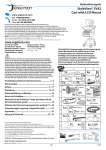
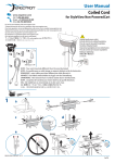
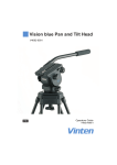
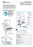
User Guide
StyleView® SV32
Patient Healthcare Delivery Laptop Cart
For the latest User Installation Guide and StyleLink Software Download please visit:
Encontrará la versión más reciente del manual de instalación del usuario y el software de StyleLink en:
Si vous souhaitez télécharger le dernier manuel d’installation de l’utilisateur ou le logiciel StyleLink, rendez-vous sur :
Den neuesten Installationsleitfaden für Benutzer sowie den neuesten StyleLink-Softwaredownload finden Sie unter:
Voor de nieuwste Installatiehandleiding voor de gebruiker en voor het downloaden van StyleLink-software gaat u naar:
Per scaricare le versioni più recenti del manuale di installazione e del software StyleLink, andare al sito:
De senaste versionerna av installationshandledningen och nedladdning av programvaran för StyleLink finns på:
最新版ユーザインストールガイドとスタイルリンク ソフトウェアは次のサイトでダウンロードできます。
请从下列地址获取最新版本的用户安装指南和 StyleLink 软件下载:
사용자 설치 안내서 및 StyleLink 소프트웨어 다운로드는 다음 웹 사이트에서 제공하고 있습니다.
http://4support.ergotron.com
User's Guide - English
Guía del usuario - Español
Manuel de l’utilisateur - Français
Gebruikersgids - Nederlands
Benutzerhandbuch - Deutsch
Guida per l’utente - Italiano
Användarhandbok - svenska
ユーザーガイド : 日本語
用户指南 : 汉语
사용자 안내서 : 대한민국
StyleView powered carts provide electrical AC power
for mobile point of care computing equipment in a
healthcare environment. The carts are not intended
to power medical products or devices. Outlets
are provided to power information technology
equipment only such as computer equipment and
computer peripherals.
IMPORTANT! This product will need tension adjustments once installation is complete. Make sure all equipment is properly installed on the product
before attempting range of motion or tension adjustments. Any time equipment is added or changed on this product resulting in a different mounted
weight, you should repeat the adjustment steps to ensure safe and optimum operation. This product should move smoothly and easily through
the full range of motion and stay where you set it. If movement is difficult or the product does not stay where you set it, follow the adjustment
instructions to loosen or tighten the tension to create a smooth, easy motion. Depending on your product and the adjustment, it may take many turns
to notice a difference.
A
1
1x
1x
1x
2
1x
4
6
3x
9x
3
5
B
1x
Features & Specifications ............................................... 2 - 4
Set-up ............................................................................ 5 - 12
Adjustment ........................................................................ 10
Battery Charge/Discharge .................................................11
Auto-Lock Drawer ...............................................................12
Change Fuse (1 Amp) and Reset Circuit Breakers ............13
Change Power System Batteries ................................ 14 - 15
Cart Storage (long term/short term) .................................16
Ergonomics .........................................................................17
Maintenance & Safety ................................................ 17 - 19
Dimensions ......................................................................... 20
1x
2x
1x
2x
14mm (9/16")
888-24-187-G-00 rev. B • 03/12
EN
1/20
Features & Specifications
WARNING
12
1b
14mm (9/16”)
1
3
1a
IMPACT HAZARD!
14
7
7a
MOVING PARTS CAN CRUSH AND CUT.
Minimize Lift Tension BEFORE:
· Removing Mounted Equipment.
· Shipping Cart
· Storing Cart
6
11
To Minimize Lift Tension
1. Lower worksurface to lowest position.
2. Turn adjustment nut at top of riser
counterclockwise until it stops
(Adjustment may require 40-60 revolutions).
9
4
2
13
5
15
8
10
Failure to heed this warning may result in
serious personal injury or property damage!
For More information and instructions refer to product
guide at http://4support.ergotron.com or contact
Ergotron Customer Care at 1-800-888-8458.
822-052
1. Worksurface:
1a. User Interface
1b. Autolock Drawer Keypad
2. Secure Storage for Laptop, Thin Client or CPU up to 3.75" (95 mm) thick
3. Front Handle
4. Height Adjustment Brake
5. USB Hub connects keyboard and mouse USB cables
6. Keyboard tray slides out, tilts and allows for right or left mousing with attached mouse holder
7. Keyboard Light under Front Handle
7a. Keyboard Light Switch
8. Cable Management and Storage for excess cables and power supplies
9. Storage Basket and Rear Handle
10. Front Locking Casters
11. Auto-Lock Drawer (see page 3 for drawer configurations)
12. Laptop Screen Holders
13. Quick Reference Card
14. Power Cord Hook
15. Power System - (see page 3 for additional information)
The StyleView AC Power System allows your power supply
to travel with the cart. The Power System is integrated in the
base of the cart and comes standard with 2 batteries, power
module, User Interface (UI), outlet box and power cord.
• User Interface (UI): Allows power system output to be
turned on or turned off, monitors battery charge remaining,
and provides low battery charge audible alarm.
• Two 33 Ah Sealed Lead Acid, Absorbed Glass Mat, 12VDC
batteries.
• The minimum operational temperature is 10°C (50°F) and
the maximum operational temperature is 29°C (86°F). The
recommended humidity range for operation is 5-95% rH.
• The recommended cart storage temperature is 15°C (59°F).
At this temperature, the battery’s age-related capacity loss is
minimized. The minimum storage temperature is -20°C (-4°F)
and the maximum storage temperature is 50°C (122°F). The
recommended humidity range for storage is 5-95% rH.
29 °C
86 °F
10 °C
50 °F
-20 °C
- 4 °F
50 °C
122 °F
Relative
Humidity 5-95% rH
Range
Relative
Humidity 5-95% rH
Range
Operational
Storage
LEAD
BATTERY
This Class A digital apparatus complies with Canadian ICES-003.
Cet appareil numérique de la classe A est conforme à la norme
NMB-003 du Canada.
FCC Compliance Statement
The cart has been tested and found to comply with the limits
for a Class A digital device, pursuant to part 15 of the FCC Rules.
These limits are designed to provide reasonable protection
against harmful interference when the equipment is operated
in a commercial environment. This equipment generates, uses,
and can radiate radio frequency energy and, if not installed and
used in accordance with the instruction manual, may cause
harmful interference to radio communications. Operation of
this equipment in a residential area is likely to cause harmful
interference in which case the user will be required to correct
the interference at his own expense.
Changes or modifications not expressly approved by
Ergotron, Inc. could void the user’s authority to operate the
equipment.
Please contact Ergotron for complete EMC compatibility
information.
888-24-187-G-00 rev. B • 03/12
2/20
EN
Features & Specifications
Part Number
Power System
Auto-Lock Drawer
SV32-6111-1
Input: 120VAC/60 Hz; 5.1A
Output: 120VAC/60 Hz, 400VA/300W.
• The cart and power system are certified to UL 60601 and CAN/CSA-C22.2 601.1-M90
1 Drawer*/6 compartments
SV32-6121-1
Input: 120VAC/60 Hz; 5.1A
Output: 120VAC/60 Hz, 400VA/300W.
• The cart and power system are certified to UL 60601 and CAN/CSA-C22.2 601.1-M90
2 Drawers*/12 compartments
SV32-6141-1
Input: 120VAC/60 Hz; 5.1A
Output: 120VAC/60 Hz, 400VA/300W.
• The cart and power system are certified to UL 60601 and CAN/CSA-C22.2 601.1-M90
4 Drawers*/9 compartments
SV32-6161-1
Input: 120VAC/60 Hz; 5.1A
Output: 120VAC/60 Hz, 400VA/300W.
• The cart and power system are certified to UL 60601 and CAN/CSA-C22.2 601.1-M90
6 Drawers*/6 compartments
SV32-6111-2
SV32-6111-3
Input: 230V~/50 Hz, 2.7A;
Output: 230V~/50 Hz, 400VA, 300W.
• The cart and power system are compliant with EN 60601-1.
1 Drawer*/6 compartments
SV32-6121-2
SV32-6121-3
Input: 230V~/50 Hz, 2.7A;
Output: 230V~/50 Hz, 400VA, 300W.
• The cart and power system are compliant with EN 60601-1.
2 Drawers*/12 compartments
SV32-6141-2
SV32-6141-3
Input: 230V~/50 Hz, 2.7A;
Output: 230V~/50 Hz, 400VA, 300W.
• The cart and power system are compliant with EN 60601-1.
4 Drawers*/9 compartments
SV32-6161-2
SV32-6161-3
Input: 230V~/50 Hz, 2.7A;
Output: 230V~/50 Hz, 400VA, 300W.
• The cart and power system are compliant with EN 60601-1.
6 Drawers*/6 compartments
SV32-6111-7
SV32-6111-8
Input: 230V~/60 Hz, 2.7A;
Output: 230V~/60 Hz, 400VA, 300W.
1 Drawer*/6 compartments
SV32-6121-7
SV32-6121-8
Input: 230V~/60 Hz, 2.7A;
Output: 230V~/60 Hz, 400VA, 300W.
2 Drawers*/12 compartments
SV32-6141-7
SV32-6141-8
Input: 230V~/60 Hz, 2.7A;
Output: 230V~/60 Hz, 400VA, 300W.
4 Drawers*/9 compartments
SV32-6161-7
SV32-6161-8
Input: 230V~/60 Hz, 2.7A;
Output: 230V~/60 Hz, 400VA, 300W.
6 Drawers*/6 compartments
*Auto-Lock Drawer
1 Drawer
2 Drawers
4 Drawers
6 Drawers
14.4"
3.4"
(367 mm)
(86 mm)
3"
(76 mm)
2.3"
11.6"
(58 mm)
11.8"
(295 mm)
(300 mm)
Drawer Insert
Weight = 2 lbs (.9 kg)
11.8"
(300 mm)
14.6"
5.5"
(370 mm)
(140 mm)
888-24-187-G-00 rev. B • 03/12
EN
3/20
Features & Specifications
12˚
20"
(508 mm)
Weight Capacity
<3 lbs (1.4 kg) Worksurface
<13 lbs (5.9 kg) Laptop Compartment
<3 lbs
(1.4 kg)
see inset, below
Total weight capacity per drawer.
<4.5 lbs (2.0 kg)
(without insert)
<0.5 lbs (0.23 kg)
Total weight capacity per
drawer.
<2.5 lbs (1.1 kg)
(with insert)
888-24-187-G-00 rev. B • 03/12
4/20
EN
Set-up
1a
1x
b
c
1x
d
e
1x
1x
2x
1x
Connect Keyboard and Mouse to USB Hub
USB (Type A)
USB (Type A)
NOTE: Bar Code Scanner should be connected directly to computer USB port.
DO NOT connect Bar Code Scanner to the USB Hub.
888-24-187-G-00 rev. B • 03/12
EN
5/20
Set-up
2a
b
Set up laptop boosters so
the screen fits through the
slot in the worksurface and
the bottom of the screen is
visible when the worksurface
is attached.
822-470-00
888-24-187-G-00 rev. B • 03/12
6/20
EN
Set-up
1x
3
4a
b
c
d
888-24-187-G-00 rev. B • 03/12
EN
7/20
Set-up
5
Place AC Power Adaptors in compartment.
a
6' (1.8 m)
Power cables need to be 6' (1.8 m) long.
Route power cable down along tower.
Route computer cables down
opening in enclosure (left or right
side.)
b
6
c
1x
a
1x
b
c
d
888-24-187-G-00 rev. B • 03/12
8/20
EN
Set-up
7
Plug the following factory connected cables into your computer.
USB: This cable runs from the USB Hub to your computer and uses your computer to power the USB Hub and Keyboard Lights. (NOTE: Your computer must be turned on for
the USB Hub and Keyboard Lights to function).
Fan: This USB cable runs from the fan to your computer so the fan will run when your computer is on.
Optional StyleLink: This USB cable runs from the power system to your computer for StyleLink Software. For more info on StyleLink visit: http://4support.ergotron.com .
WARNING: Fan must always be running when computer is on. Operating computer without fan may
lead to overheating, resulting in reduced equipment performance.
8
9
888-24-187-G-00 rev. B • 03/12
EN
9/20
Adjustment
10
It is important that you adjust this product according to the weight of the mounted equipment as described in the following steps. Any time equipment is added or removed from this
product, resulting in a change in the weight of the mounted load, you should repeat these adjustment steps to ensure safe and optimum operation.
Adjustments should move smoothly and easily through the full range of motion and stay where you set it. If adjustments are difficult and do not stay in the desired position, follow
the instructions to loosen or tighten the tension to create a smooth, easy adjustment motion. Depending on your product and the adjustment, it may take several turns to notice a
difference.
Lift – Up and down
Release Brake to move riser.
Follow these instructions to tighten or loosen tension.
i
ii
1x
14mm (9/16")
NOTE: Adjustment may require 40 - 60
revolutions.
11
12
1x
1x
Keyboard Light
Keyboard Light will automatically turn off after 15 minutes if not
manually turned off.
888-24-187-G-00 rev. B • 03/12
10/20
EN
Battery Charge/Discharge
13
a
Initial Power on/Charge Battery (takes aproximately 7 hours to charge)
Plug Cart's Power Cord into wall outlet.
b
Turn on power system by holding power buttondown for 1 - 3 seconds.
c
With cart's power cord plugged into the wall outlet, wait until cart
is at 100% charge. (takes aproximately up to 7 hours to charge)
Do Not stretch coiled cord further than 8 feet
(2.5 meters), damage to the cord may occur.
CAUTION: There is no on/off switch on
this equipment; the AC power cord is the only
power disconnect. The socket outlet should be
easily accessible and should be installed near the
equipment.
Note: If StyleLink is installed, it will report battery status “checking” until battery has gone through one full cycle (charge to 100%, discharge to
< 70%, and then plug cart into wall outlet). After battery has gone through one full cycle, StyleLink will provide battery status. In the event that
StyleLink still reports status “checking’, repeat the discharge / recharge and plug in.
7
hrs
8hrs
07.00
This power system interface will alert you to the percentage of charge remaining in the cart battery with a series of steady or flashing
red, yellow or green lights, and an alarm that will beep when charge gets below 30%. Remember, the battery needs to be charged to
100% every day, and you can use the cart while charging, so plug-in cord as often as possible to avoid running out of power!
NOTE: Put monitor in power save mode to optimize battery run time.
Battery has 100% charge.
Light flashes when charging (power cord plugged into wall outlet) Allow battery to continue
charging until light stops flashing. After light stops flashing, it is OK to unplug the
power cord from the wall. You can use cart while charging.
Battery has less than 90% charge.
Battery has less than 70% charge.
Battery has less than 50% charge.
Battery has less than 30% charge. Light is red and alarm beeps. Plug-in power cord and charge
to 100%! You can use cart while charging.
When lit, alarm is enabled and
will beep when battery charge
gets below 30%. For details on
enabling and disabling alarm
contact Ergotron Customer Care.
Alarm Mute button. Pressing this will temporarily mute alarm.
Power button for internal power system outlets. Pressing this will provide or remove power to/
from components plugged into the internal outlets.
When lit, the power system is on.
When dark, power system is off.
NOTE: Frequent operation of the cart while battery charge levels are
below 30% will significantly reduce the life of your battery and may
void your battery warranty.
888-24-187-G-00 rev. B • 03/12
EN
11/20
Auto-Lock Drawer
14
NOTE: User should change Master Personal Identification Number (PIN)
upon receipt of cart.
1x
Lost Master PIN
Contact Ergotron Customer Care for instructions.
Ensure that the main power system batteries are installed and functioning. The power
does not need to be turned on at the power system user interface.
Set-up Master PIN for the First Time (Default Master PIN: 12345)
Contact Ergotron Customer Care for instructions if Master PIN is lost.
1. Enter Master PIN (All numbers associated with available drawers will light).
2. Simultaneously press 3 and 5 (Numbers 3 and 5 will light green).
3. Simultaneously press 3 and 5 again (Numbers 3 and 5 will flash green).
4. Simultaneously press 3 and 5 a third time (All numbers will light green). You have 5 seconds to enter the new Master PIN.
5. Input new 5 digit Master PIN (All numbers will flash green).
6. Wait 5 seconds for system to exit program mode (All numbers will flash green several times).
Programming User PINS
1. Enter Master PIN (All numbers associated with available drawers will light).
2. Simultaneously press 4 and 6 (Numbers 4 and 6 will light green).
3. Simultaneously press 4 and 6 again (Numbers 4 and 6 will flash green).
4. Simultaneously press 4 and 6 a third time (All numbers will light green). You have 10 seconds to enter a new User PIN.
5. Input new 5 digit User PIN (All numbers will flash green). You can continue to enter 5 digit User PINs until finished.
After sitting idle for 10 seconds, system will exit program mode (All numbers will flash green several times).
NOTE: System will hold up to 100 User PINs. Once 100 User PINs storage is exceeded, the oldest User PIN will be overwritten by the next User PIN programmed.
Unlock Drawer (3 methods):
• Enter Master PIN, then press desired drawer number*.
• Enter User PIN, then press desired drawer number*.
• Key - turn clockwise 1/4 turn
*Drawer Numbers:
1
1
1
2
2
3
4
1
4
2
5
3
6
Lock Drawer:
• Wait 4 seconds for lock to engage automatically.
NOTE: Drawer must be fully closed to lock.
Drawer Troubleshooting
• Key pad numbers are dark:
- Touch anywhere on number pad to activate back-light, (drawer remains locked until you enter valid PIN).
- Check to make sure DC cable is connected.
• Drawer won’t open when User PIN is entered:
- Test system by entering Master PIN. If drawer doesn’t unlock, contact Ergotron customer care for "Lost Master PIN" instructions.
Lights: Meaning
1,2,3,4,5 or 6 and Red mute button
Flashing and alarm sounding: Drawer is open longer than 20 seconds. Mute button can be pressed to mute alarm.
System will not function until drawer is shut and locked.
The number corresponding to the open drawer will Flash Red on the keypad.
All available drawer numbers
Flashing Green: Waiting for drawer selection (see Unlock Drawer)
All available drawer numbers
Flashing Red: Firmware upgrade is happening
All flash once: New code accepted.
All flash three times: Exiting program mode.
USB
1 1,2,3
2/4
4,5,6
888-24-187-G-00 rev. B • 03/12
12/20
EN
Change Fuse and Reset Circuit Breakers
1
2
Turn off all mounted equipment.
Disconnect Power System from
power source.
3
Turn power system off by
holding down the AC Outlet
Power button for 1 - 3 seconds.
Power light will shut off.
4
5
1 Amp Fuse
Recommended:
Littelfuse 312001P
6
Before reseting circuit breakers,
contact Ergotron to determine
cause of trip.
7
888-24-187-G-00 rev. B • 03/12
EN
13/20
Change Power System Batteries
33 Amp-Hour Batteries
WARNING:
RISK OF ELECTRICAL DISCHARGE
• Do NOT swap battery cables, doing so will cause arcing and trip
the circuit breaker.
• Do not remove or replace the batteries while cart is located in
an oxygen rich or hazardous environment, arcing may occur and
cause combustion.
• Replace first battery before removing second battery to reduce
the risk of cables touching terminals and causing arcing.
LEAD
WARNING
BATTERY
IMPORTANT REPLACEMENT BATTERY INFORMATION
The power module is configured for two, 33 -Ah batteries. Only the following
batteries are compatible with this system:
t##&1
t4#44
t-POHXBZ'.(
t7JTJPO'.%
t1#21#2t8FSLFS8,"$t8FSLFS8,"$
• Always replace both batteries!
• Replace first battery before removing second battery.
• Replace batteries with same Amp/Hour rating batteries only.
• Only Ergotron-specified batteries may be used in the StyleView
Power System. Please call customer care for more details.
• Recycle battery or contact Ergotron for proper battery disposal
guidelines.
Installing batteries other than the 33 -Ah listed above will void the product warranty.
Failure to heed this warning may result in severe damage to batteries, power module
BOEQPTTJCMFöSFIB[BSE$POUBDU&SHPUSPOGPSNPSFJOGPSNBUJPOBU
822-386-03
1
2
Turn off all mounted equipment.
3
Disconnect
Power System
from power
source.
Turn power system off by holding down
the AC Outlet Power button for 1 - 3
seconds. Power light will shut off.
4
5
Turn both circuit breakers to "OFF".
6
LEAD
Caution: Replace only one battery at a time.
Do NOT swap battery cables, doing so will cause
sparking and trip the circuit breakers.
Recycle battery or contact
Ergotron for proper battery
disposal guidelines.
BATTERY
a
c
Caution: Remove Black (-) before removing Red (+).
b
Red
Black
7 d
e
Caution: Connect Red (+) before connecting Black (-).
Red
f
Black
888-24-187-G-00 rev. B • 03/12
14/20
EN
Change Power System Batteries
8
LEAD
Recycle battery or contact
Ergotron for proper battery
disposal guidelines.
BATTERY
a
c
Caution: Remove Black (-) before removing Red (+).
b
Black
9 d
Red
e
Caution: Connect Red (+) before connecting Black (-).
Red
f
Black
10
11
12 Follow Battery Charge/Discharge Initial Power on steps.
888-24-187-G-00 rev. B • 03/12
EN
15/20
Cart Storage
Short Term Storage - If the Power System will be idle for up to 3 months, the battery should be fully charged before storage and recharged during storage.
Long Term Storage - If the Power System will be idle for 3 months or more, the battery should be removed from the cart and recharged during storage.
Short Term Storage - If the Power System will be idle for up to three months, the battery should be fully charged before storage and recharged during storage.
1
3
2
Turn off all mounted equipment.
Plug power cord into
appropriate wall outlet to
fully charge battery to 100%
(all indicator lights will be
illuminated). Power system
must be fully charged
before storing!
Once battery has been charged to 100%, turn power system off.
a. Turn power system off by holding down the AC Outlet Power button for 1 - 3 seconds. Power light will shut off.
b. Turn both circuit breakers to "OFF".
a
b
NOTICE:
Warranty on fully charged batteries left in an unused state for more than three (3) consecutive months is automatically void.
Warranty on fully discharged batteries left in an unused state for more than three (3) consecutive days is automatically void.
Long Term Storage - If the Power System will be idle for 3 months or more, the battery should be removed from the cart and recharged during storage.
WARNING: Do not remove or replace the batteries while cart is located in an oxygen rich or hazardous environment. Sparking may occur.
1
2
Turn off all mounted equipment.
3
Disconnect
Power System
from power
source.
Turn power system off by holding
down the AC Outlet Power button for
1 - 3 seconds. Power light will shut off.
4
5
Turn both circuit breakers to "OFF".
Caution: Remove Black (-) before removing Red (+).
6
8
Black
10mm
7
Red
11
Store battery in cool, dry area while Cart is out of use. Optimal storage temperature is
15°C/59°F. Battery voltage should be checked every three (3) months. If voltage drops
below 12.5VDC, fully recharge battery. Contact Ergotron Customer Care for information
about how storage might impact the battery warranty.
9
888-24-187-G-00 rev. B • 03/12
16/20
EN
Ergonomics
Working
Moving
customize - to your size
stow - before you go
1 Set top of monitor screen about one inch below eye level - Release brake and lift or lower riser
as needed.
1 During normal movement, release brake and lower worksurface to
lowest position for optimal stability and unobstructed view.
2 Tilt screen for comfortable viewing and to reduce eye and neck strain.
2 Tuck away open trays and return mouse, scanner and other accessories
to their places.
3 Pull keyboard tray forward and position mouse tray and mouse pouch on right or left, as needed.
3 Unlock both front casters.
4 Work with elbows bent at about 90° to minimize muscle strain.
5 If the riser moves up and down with difficulty, or if it drifts out of set position, consult the product
manual for adjustment information.
6 Stay in charge!
Powered carts should be plugged into outlet as often as possible to keep battery charged and
computer running.
4 Push cart from rear with elbows bent at about 90° to maximize control
and minimize muscle strain.
5 Don’t run out!
Before moving, make sure cord is unplugged from outlet and hooked to
basket for safe travel. Remember, charge battery fully 100% every day!
1
1
2
4
3
4
5
5
2
6
3
Maintenance & Safety
Hazard Symbols Review
The Meaning of Symbols appearing in this Guide, on the Cart or on the Power System
These symbols alert you to a safety condition that demands your attention. You should be able to recognize and
understand the significance of the following Safety Hazards if you encounter them on the Cart or within Cart
documentation such as this Set-up Guide.
Signal
Word
Level of Hazard
Red
DANGER
Indicates an imminently hazardous situation which, if not
avoided, will result in death or serious injury.
Orange
WARNING
Indicates a potentially hazardous situation which, if not
avoided, could result in death or serious injury.
Yellow
CAUTION
Indicates a potentially hazardous situation which, if not
avoided, may result in minor or moderate injury.
None
CAUTION
Used without the safety alert symbol indicates a potentially hazardous situation which, if not avoided, may
result in property damage.
Red,
Orange
or
Yellow
Electrical
Indicates an impending electrical hazard which, if not
avoided, may result in personal injury, fire and/or death.
Color
Symbol
EQUIPMENT & ACCESSORIES DISPOSAL
1. Please dispose of all batteries in accordance with
local law
2. All Electronics should be recycled through an
electronics recycler.
3. Remaining plastics and metals can be recycled
through a commercial recycler.
888-24-187-G-00 rev. B • 03/12
EN
17/20
Maintenance & Safety
Cleaning and Maintenance
The following procedures are not guaranteed to control infection. The hospital infection control administrator or epidemiologist should be consulted regarding cleaning procedures
and processes.
To avoid risk of electric shock, do not expose electrical components to water, cleaning solutions or other potentially corrosive liquids or substances.
Do not immerse Cart or Cart components in liquid or allow liquids to flow into the Cart. Wipe all cleaners off surface immediately using a damp cloth. Thoroughly dry surface
after cleaning.
Do not use flammable cleaners on Cart surfaces due to close proximity of electrical power and equipment.
All paints and plastic Cart components will withstand cleaning by most commonly used, diluted, non-abrasive solutions such as quaternary ammonia compounds, ammonia
enzyme cleaners, bleach or alcohol solutions.
• Pen and permanent and dry erase markers can be removed with 91% isopropyl alcohol and a soft cloth.
• Iodine stains can be removed with commonly used cleaners and a soft cloth.
• Never use steel wool or other abrasive materials that will damage the surface finish.
• Do not use strong solvents such as trichloroethylene and acetone. These solvents will damage the surface finish.
It is recommended that any cleaning solution be tested on a small, inconspicuous area to ensure surface is not harmed.
Adjustment, Service, Replacement - DO NOT attempt to adjust, service or replace any part of the StyleView Cart unless directed to do so through Ergotron-approved
documentation (i.e. installation instructions). Only Ergotron, Inc. or an Ergotron-certified entity may adjust, service or replace StyleView Cart components. If any component on the
Cart is missing or damaged, the Cart must not be used, contact Ergotron Customer Care immediately to request a replacement part.
Cables - Keep cables neatly organized on the Cart (a variety of solutions are provided with your cart for this purpose). Excess cables should be routed away from moving
components with cable clips. Review Cable Routing section of this guide, or contact Ergotron Customer Care for more information.
Casters - Check casters periodically to make sure they are clean and free of debris that would prevent smooth travel. Avoid moving Cart across uneven, dirty or damaged
surfaces.
Customer Equipment- Make sure equipment is balanced and mounted securely to Cart. Do not reposition Cart components on riser or tower unless instructed to do so in the
installation instructions. Moving Cart components too high or too low on the Riser may create an unstable condition, leading to equipment damage or even personal injury. Contact
Ergotron Customer Care for information about moving Cart components.
Recommended Periodic Inspection and Maintenance
Component
Action
How often
By whom
ALD Batteries
(SV31 only)
Replace 4 ea AA NiMH batteries1
Replace when
keypad #4 flashing
Any user
UI, USB cables
Inspect for wear, pinching, bad
connectors
Monthly
Any user
Fan on side of CPU
compartment
Inspect for dust at intake, vacuum
as required using a vacuum cleaner
that DOES NOT generate ESD
(Electrostatic Discharge)
Monthly
Any user
Casters
Inspect for wear and debris
Monthly
Any user
Maximum Load
Inspect to ensure that maximum
recommended loads are not
exceeded
Daily
Any user
Power System SLA
batteries
Replace lead acid batteries1,2
When instructed
by StyleLink or
when battery
runtime is 80% of
original runtime
IT Personnel
Power Module
Inspect for dust at intake, vacuum
as required using a vacuum cleaner
that DOES NOT generate ESD
(Electrostatic Discharge)
Monthly
IT Personnel
Battery harness
Inspect for wear, cracking, pinching,
or other damage
Monthly
IT Personnel
Coiled Cord
Inspect for wear, damage, or
stretching.
Weekly
Any user
1. Please dispose of all batteries in accordance with local law
2. Always replace with similar size battery (33 A-h to replace 33 A-h) and always replace in pairs
Earth Bond Test: To ensure safety grounding between the
power cord ground connection and any accessible metal
parts on the cart, although not mandatory, the following test
is recommended to be performed every two years using a
calibrated medical device safety analyzer. The procedure is as
follows:
1. Disconnect the cart from mains power (unplug cart from the
wall).
2. Remove power from internal power system outlets by
pressing the power button on the Power System Interface.
3. Set up Earth Bond Test per the medical device safety analyzer
instructions.
4. Connect the Cart power cord to the medical device safety
analyzer.
5. Remove cover to access Lift Tension Adjustment point.
6. Attach second medical safety device analyzer probe to Lift
Tension Adjustment point on Cart.
7. Perform Test (25 amps).
8. Ensure Earth Bond is less than or equal to 0.2-ohms.
9. Remove medical device safety analyzer connections to Cart,
replace cover over Lift Tension Adjustment point, return the
Cart to service.
Insulation Resistance Test: To ensure mains power lines are
adequately insulated from earth ground, the following test,
although not mandatory, is recommended to be performed
annually using a calibrated medical device safety analyzer. The
procedure is as follows:
1. Disconnect the cart from mains power (unplug cart from the
wall).
2. Remove power from internal power system outlets by
pressing the power button on the Power System Interface.
3. Set up the Insulation Resistance Test per the medical device
safety analyzer instructions.
4. Connect the Cart power cord to the medical device safety
analyzer.
5. Perform test (500 V).
6. Ensure Insulation Resistance is greater than or equal to 1
Mohms.
7. Remove medical device safety analyzer connections to Cart
and return Cart to service.
888-24-187-G-00 rev. B • 03/12
18/20
EN
Maintenance & Safety
Safety Alerts Associated with this Product
The following Warnings/Cautions appear in this reference guide or on
the cart:
NOTE: Failure to adhere to these guidelines may result in equipment
damage or personal injury.
CAUTION: The lift brake helps stablilize the worksurface and
keyboard tray during normal use but it DOES NOT increase load capacity.
DO NOT load riser with equipment totaling more than the maximum
weight capacity specified by Ergotron. Ensure optimum lift function
by testing and if necessary, re-adjusting tension whenever the weight
mounted to the riser changes (i.e., equipment is removed or added). See
"Set Riser Lift Tension" adjustment instructions.
CAUTION: Do not operate StyleView Cart with missing or damaged
components! Do not remove, modify or substitute Cart components
without consulting Ergotron. If you encounter problems with Cart
installation or operation, contact Ergotron Customer Care.
CAUTION: DO NOT overtighten fasteners. Overtightening may cause
damage to your equipment.
WARNING: Stored Energy Hazard: The worksurface lift mechanism is
under tension and will move up rapidly, on its own, as soon as attached
equipment is removed. For this reason, DO NOT remove equipment
unless the worksurface has been moved to the highest position on the
tower! Failure to follow this instruction may result in serious personal
injury and/or equipment damage! When Shipping the cart, set the
worksurface lift mechanism to the lowest tension setting.
Ergotron Electromagnetic Guidance and Manufacturer’s Declaration
Guidance and Manufacturer’s Declaration – Electromagnetic Emissions
The Powered Computer Cart is intended for use in the electromagnetic environment specified
below. The customer or the user of the Powered Computer Cart should assure that it is used in
such an environment.
Emissions Test
Compliance
Electromagnetic environment – guidance
RF Emissions
CISPR 11
Group 1
The Powered Computer Cart uses RF energy only for its
internal function. Therefore, its RF emissions are very
low and unlikely to cause any interference in nearby
electronic equipment.
RF Emissions
CISPR 11
Class A
Harmonic Emissions
IEC 61000-3-2
Class A
The Powered Computer Cart is suitable for use in all
establishments other than domestic and those directly
connected to the public low-voltage power supply
network that supplies buildings used for domestic
purposes.
Voltage fluctuations/
flicker emissions
IEC 61000-3-3
Complies
CAUTION: DO NOT loosen, tighten or remove any other nuts or
bolts on the riser or top of tower. Tampering with nuts or bolts may result
in an unstable Cart, leading to equipment damage and/or personal
injury.
Guidance and Manufacturer’s Declaration – Electromagnetic Immunity
CAUTION: Release Lift Brake before moving work surface! Moving
work surface while Lift Brake is engaged may cause serious damage to
Lift Engine.
Immunity Test
IEC 60601
Test Level
Compliance
Level
Electromagnetic environment
- guidance
Electrostatic
Discharge (ESD)
IEC 61000-4-2
±6 kV contact
±8 kV air
Complies
Floors should be wood,
concrete, or ceramic tile. If floors
are covered with synthetic
material, the relative humidity
should be at least 30%
Electrical Fast
Transient/Burst
IEC 61000-4-3
±2 kV for power supply lines
±1 kV for input/output lines
Complies
Mains power quality should be
that of a typical commercial or
hospital environment.
Surge
IEC 61000-4-5
±1 kV differential mode
±2 kV common mode
Complies
Mains power quality should be
that of a typical commercial or
hospital environment
Voltage
Dips, short
interruptions,
and voltage
variations on
power supply
input lines
IEC 61000-4-11
<5% UT
(>95% dip in UT) for 0.5 cycle
40% UT
(60% dip in UT) for 5 cycles
70% UT
(30% dip in UT) for 25 cycles
<5% UT
(>95% dip in UT) for 5
seconds
Complies
Mains power quality should be
that of a typical commercial or
hospital environment.
Power
Frequency
(50/60 Hz)
Magnetic Field
IEC 61000-4-8
3 A/m
Complies
Power frequency magnetic
fields should be at levels
characteristic of a typical
location in a typical commercial
or hospital environment.
WARNING: In the event that repair of the StyleView Cart is needed,
contact Ergotron Customer Care immediately. Cart repair can only be
performed by Ergotron, Inc. or by an Ergotron authorized agent.
WARNING: This cart is not intended for use in a flammable,
anesthetic mixture or oxygen rich environment.
$!.'%2
ELECTRICAL CORDS CAN BE HAZARDOUS
-ISUSE#AN2ESULTIN&)2%OR$%!4(BY%,%#42)#!,3(/#+
0LEASE2EADAND&OLLOW0RODUCT-ANUAL)NSTRUCTIONS
4()3)3!0/,!2):%$#/2$(/30)4!,'2!$%/.,9
./4%'ROUNDING2ELIABILITY#AN/NLY"E!CHIEVED7HEN
THE%QUIPMENT)S#ONNECTED4O!N%QUIVALENT2ECEPTACLE-ARKED
h(/30)4!,/.,9v/Rh(/30)4!,'2!$%v
s)NSPECT#ORD4HOROUGHLY"EFORE%ACH5SE$/./453%)&$!-!'%$
s$O.OT0LUG-ORE4HAN30%#)&)%$.5-"%2/&7!443)NTO0OWER3YSTEM
s$O.OT2UN#ORD4HROUGH$OORWAYS(OLESIN#EILINGS7ALLSOR&LOORS
s&5,,9).3%240LUG)NTO/UTLET
s$O.OT2EMOVE"ENDOR-ODIFY!NY-ETAL0RONGSOR0INSOF#ORD
s$O.OT5SE%XCESSIVE&ORCETO-AKE#ONNECTIONS
s+EEP!WAY&ROM7ATER$/./453%7(%.7%4
s+EEP#HILDREN!WAY&ROM#ORD
s$O.OT0LUG#ORDINTO!N%XTENSION#ORD
s!6/)$/6%2(%!4).'5NCOIL#ORDAND$O.OT#OVER)T7ITH!NY-ATERIAL
s$O.OT$RIVE$RAGOR0LACE/BJECTS/VER#ORD$O.OT7ALK/N#ORD
s'2!300,5'TO2%-/6%&2/-/UTLET$O.OT5NPLUG"Y0ULLING/N#ORD
The Powered Computer Cart is intended for use in the electromagnetic environment specified
below. The customer or the user of the Powered Computer Cart should assure that it is used in such
an environment.
Note: UT is the AC mains voltage prior to application of the test level
888-24-187-G-00 rev. B • 03/12
EN
19/20
Features & Specifications
< 15.3”
(390 mm)
34.5"
(876 mm)
30.6”- 50.6”
4.4"
(778-1285 mm)
(112 mm)
13.4"
(340 mm)
8.8"
(224 mm)
5.3"
8.1"
(134 mm)
47.2"
1.65"
(206 mm)
(1199 mm)
(79 mm)
(51mm)
24.2" - 44.2"
(1016 mm)
16.9"
(429 mm)
(614-1123 mm)
22"
(710 mm)
(41.8 mm)
2"
40"
28"
3.1"
17.7"
(450 mm)
(560 mm)
12"
(305 mm)
21.4"
(545 mm)
1.5"
18.7"
(40 mm)
(475 mm)
Laptop Compartment
4"
12.5"
(101.6 mm)
(318 mm)
15.5"
4"
(102 mm)
(432 mm)
When figuring dimensions, include
mounted accessories, protruding
cables and port replicators or docking
stations.
17"
(432 mm)
888-24-187-G-00 rev. B • 03/12
20/20
EN