1
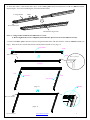
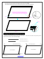
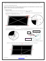
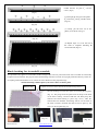
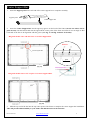
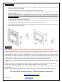
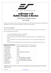
ezFrame & Sable Frame Series Fixed Frame Projection Screen User’s Guide Hardware and Parts List 1. Frame Parts x 6 pcs (4 top/bottom horizontal frame pcs + 2 side vertical frame pcs) 2. Tension Rods x 6 pcs (4 top/bottom rods + 2 side rods) 3. Screen Material x 1 pc 4. Center joints 5. Elbow Joints x 2 pcs x 4 pcs 6. Wall brackets x 2 – 3 pcs (depending on model/size) 7. M5x50 wood screws 8. Hollow wall anchor 9. M5x15 screws x 6 pcs x 6 pcs x 16 pcs 10. Center Support Bar x 1 – 2 pcs (depending on model/size) 11. Support joiner x 2 – 4 pcs (depending on model/size) 12. Fix Plates x 60 – 180 pcs (depending on model/size) Note: Please make sure all parts are included in your package before proceeding to assemble your Elite Screens fixed frame projection screen. FRAME ASSEMBLY 1. Insert the center joint connector into to one of the 1/2 horizontal frames and fasten it with two M5x15 screws. M5×15 screws ½ Horizontal Frame bevel connection Rev.041014-JA www.elitescreens.com 1 2. Insert the other 1/2 horizontal frame piece to the center joint connector and fasten it with two M5x15 screws. Repeat steps 1 and 2 for assembling the second horizontal frame. ½ Long Frame Push bevel connection Horizontal Long Frame Note: a. 2 long frames should be assembled for a screen. b. Do not tighten the screws completely until all frame pieces have been assembled correctly. 3. Insert both elbow joint connectors into the long horizontal frame and then fasten it with two M5x15 screws (see Fig.1). Then insert the vertical short frames and fasten them with screws (fig.1.2) Long frame Push Push M5×15 screws Joint M5×15 screws ( fig.1) Push Push Short frame Short frame Screw (Fig.1.1) M5×15 screws (Fig.1.2) ( fig.3) Rev.041014-JA www.elitescreens.com 2 Join all four frame parts together following the steps shown below. (Fig.2) Note: When assembled, please push simultaneously the two ends of the long frames. 4. Insert the exposed ends of the joint connectors into the short (vertical) frame and align the four corners so that they meet at perfect right angles Push Push M5×15 screws Screw ( fig.2) Attaching the screen material ( fig.3) to the frame 1. Unroll the screen material and lay it down on a clean surface. edges of all four corners of the material (see fig.3) Then insert the tension rods separately into the Tension Rod (Vertical) x 2 Tension Rod (Horizontal) x 4 push push Tension Rod (Horizontal) x 4 Tension Rod (Vertical) x 2 push push Screen Material Screen Material (Fig. 3) push Rev.041014-JA push www.elitescreens.com 3 2. Make sure that the material and frame are both lying face down on a clean, dry, and non-abrasive surface. 3. Center the material inside the frame. Please note the material will be noticeably smaller than the frame, as the material must be stretched to create a sufficient amount of tension for perfect material flatness. 4. Attach the fix plates (1) Begin by securing the four corners in the following order A→ B→ C→ D (Fig.4) (2) Insert the fix plates as shown on Fig. 5. Fix plate ① is approximately 10 cm away from the frame’s corner and fix plate ② is approximately 5cm away. C A B D (Fig. 4) (Fig. 5) (3) Stretch the material to the corner and insert the screen material’s edge into the groove of the frame. While one hand holds the material in place, the other hand snaps in the push plate (Fig.6-Fig.7). Insert push plate in Plate Tension Rod (Fig. 7) (Fig. 6) Schematic Cross section of the Frame (4) Place a fix plate in the center of each side in the following order E→F→G→H. (Fig.8) E . H G F Rev.041014-JA www.elitescreens.com (Fig.8) 4 (5) Put the next set of fix plates ② in the middle between fix plate ① and the corner. (Fig.9) (Fig.9) (6) Then put the next set of fix plates ③ between ①and ② and the corner. (Fig.10) (Fig.10) (7) Lastly, put the next set of fix plates (4) as shown in Fig.11 (Fig.11) (8) Repeat steps 5-7 to for the rest of the sides to complete attaching the screen material (Fig.12) (Fig.12) Black backing for AcousticPro models This procedure only applies to AcousticPro models. Disregard this section if your Fixed Frame does not include an acoustically transparent screen material. The purpose of the black backing material is to block out any light penetration that may reflect off of anything mounted behind the screen, which can cause distortion to the projected image. The black backing is held in place by the Velcro that is on the fix plates. Black backing Fix plates secure the Acoustic material and the black backing behind it. Interval markings reveal the best points for inserting the fix plates (Fig. 13). The prongs on the fix plates insert to the lip on the back of the frame creating a friction hold that will firmly keep the material and black backing in place (Fig. 14-15). After the material has been installed, the backing will lie over the back of the white (Acoustic) material and then be held in place by the Velcro on the fix plates (Fig 16). (Fig. 13) Rev.041014-JA (Fig. 14) www.elitescreens.com (Fig. 15) (Fig. 16) 5 Center Support Bard 1. Insert the support joiner into each end of the center support bar to complete assembly. support joiner Center support bar 2. Insert the Center Support Bar into the upper top groove on the back of the frame (not the one where the fix plate inserts) with the bottom end near the approximate center point of the frame and rotate it in at an angle so that both ends of the bar are in alignment with the groove (see Fig. 17 and Fig. 18 below for details). Diagonal models 135” and below use 1x Center Support Bar Remove Center Support Bar push (Fig. 17) Center Support Bar Diagonal models above 135” require 2 x Center Support Bars (Fig. 18) 3. Slide the top end of the bar into the top center point of the frame to complete the center support bar installation. This will provide added stability to your frame and added tension to the material. Rev.041014-JA www.elitescreens.com 6 Installation 1. Locate your desired installation location with a stud finder (recommended) and mark the drill-hole area of where the screen is to be installed. 2. Drill a hole with the proper bit size according to the wood screws included. 3. Line up the wall brackets with the drilled holes on the installation location and screw them in using a Phillips screwdriver. Note: Use 2 top wall brackets on diagonal sizes below 135”, and use 3 top wall brackets on diagonal sizes 135” and above. 4. Position the fixed frame screen onto the top wall brackets as shown in (Fig. 19) and push down at the center of the bottom frame to secure the installation. 5. The design of the wall brackets allows the frame to slide over them through its sides. This is an important feature of the installation design as it allows your screen to be properly centered. 6. Using both hands finish the installation by pushing the lower portion of the fixed frame screen into the lower bracket as shown in Fig 20. (Fig.20) (Fig. 19) CAUTION Please follow these instructions carefully to ensure proper maintenance and safety of your Fixed Frame Screen 1. When hanging the screen up, please make sure that no other objects such as power switches, outlets, furniture, ladders, windows, etc. occupy the space designated for your Fixed-‐Frame screen. 2. Regardless if the screen is hung on or installed into the wall, make sure that the proper mounting anchors are used and that the weight is supported appropriately by a strong and structurally sound surface just as any large and heavy picture frame should. (Please consult a home improvement specialist for the best advice on installation) 3. Frame parts are made of high quality velour-‐surfaced aluminum and should be handled with care. 4. When not in use, cover over the screen with a furniture sheet to protect it from dirt, grime, paint or any other impurities. 5. When cleaning, use a damp soft cloth with warm water to remove any marks on the frame or screen surface. 6. Never attempt to use any solutions, chemicals or abrasive cleaners on the screen surface. 7. In order to avoid damaging the screen, avoid touching it directly with your fingers, tools or any other sharp or abrasive objects. 8. Spare Parts should be placed out of reach of small children in accordance with household safety guidelines. For a local Elite Screens contact or Technical Support, please visit www.elitescreens.com Rev.041014-JA www.elitescreens.com 7