1
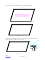
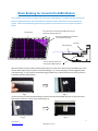
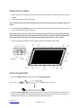
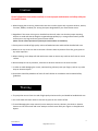
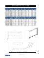
 Fixed
F
F
Frame
P
Projectio
on Screeen
Cin
nem
ma23
35 Seri
S ies
User’s Guide 1 Rev.051811‐A
AS www.elitescrreens.com info@
@elitescreens.com Parts List for the Cinema235 Series
Please make sure all parts listed below are included before proceeding with the installation. 1. Frame Parts x 6 pcs (4 Top & Bottom frame pcs + 2 Side frame pcs) 2. Tension Rods x 6 pcs (4 Top & Bottom frame rods + 2 Side rods) 3. Screen Material x 1 pc 4. Center Joints x 2 pcs 5. Elbow Joints x 4 pcs 6. Wall Brackets x 2‐3 pcs (depending on size) 7. Screws x 16 pcs 8. User Guide x 1 pc 9. Center Support Bar x 1‐2 pcs (depending on size) 10. Support Joiner x 2‐4 pcs (depending on size) 11. Fix Plates x 30‐90 pcs (depending on size) 12. Black Cloth Backing x 1 pc (AcousticPro 1080 models only) Installation Instructions
Assemble the Frame 1. Insert the Center Joint Connector to the horizontal frame piece and secure with screws. 2 Rev.051811‐AS www.elitescreens.com [email protected] 2. Insert the other horizontal frame piece to the Center Joint connector and secure with screws. 1/2Long frame Push Note: To make sure the frame pieces line up correctly, do not tighten the screws until assembly is complete. 3. Insert both Elbow Joint connectors into the long horizontal frame (see fig. 1). Long frame
Push
Push
Joint
( fig.1)
P ush
P ush
S h o rt fra m e
S h o rt fra m e
3 Rev.051811‐AS www.elitescreens.com [email protected] 4. Join all four frame parts together following the steps showed below (see fig. 2) Insert the exposed ends of the joint connectors
into the short (vertical) frame and align the four
corners so that they meet at perfect right angles
Push
Push
( fig.2)
5. Make sure all four corners join correctly to form a perfect rectangle, then fasten the four angles together by using the included joint screws. (see fig. 3)
Screw
( fig.3)
4 Rev.051811‐AS www.elitescreens.com [email protected] Attach the Screen Material to the Frame 1. Lay out the material and Tension Rods on a clean & dry surface. Insert the Tension Rods through the sleeves according to their corresponding lengths on each edge of the screen (see fig. 4). Tension Rod (Horizontal) x 4 Tension Rod (Vertical) x 2 Screen
Push
Steel rod
Steel rod
Push
( fig.4)
2. Place the screen material on the back of the frame and insert the tension rods into the grooves running of each corner of the frame. Insert the Fix Plates to the back of the frame to secure the rods into place creating tension for a flat surface (see fig. 5 & 6). fix plate
Push
Viewing surface
(Front of screen)
Steel rod
( fig.5)
5 Rev.051811‐AS www.elitescreens.com [email protected] Black Backing for AcousticPro1080 Models This procedure only applies to models with AcousticPro 1080 Material. The Black Backing counters the effects of light penetration that would otherwise light up all items behind the screen and spoil the picture. Attach the Black Backing behind the projection surface and secure to the Velcro‐Faced Fix Plates. Fix plate secures AcousticPro1080 material and the black backing behind it. Black backing AcousticPro1080 Screen Material Cover by Black backing Fix Plate Black backing Tension Rod (stretches the AcousticPro1080 material) After the material has been installed, the backing will lie over the back of the white (AcousticPro1080) material and then be held into place by the fix plates as they are added (fig. 1‐3). Interval markings reveal the suggested points of attachment (fig. 1). The prongs on the fix plates (fig.2) straddle a lip on the back of the frame creating a friction to hold the material in place (fig.3‐4). Fig.1 Fig.2 *An alternate way to attach the black backing to the back of the AcousticPro1080 material is to utilize the Velcro tabs located on the outer surface of the fix plates (fig.3‐4) Fig. 4 Fig. 3 6 Rev.051811‐AS www.elitescreens.com [email protected] Attach the Fix Plates 1. Make sure that the material and frame are both lying face down on a clean, dry and non‐abrasive surface. 2. Center the material inside of the frame Note: The material was made smaller than the frame in order to be stretched to create a sufficient amount of tension. 3. Start attaching the Fix Plates in the center of each horizontal frame piece (1), then in the center of each vertical frame piece (2). (see fig.7) Note: Follow these instructions to make sure the material is properly fixed in the center position of the frame. After attaching the fix plates in sequence #2 (vertical sides), remove the fix plates in sequence #1 (horizontal pieces) and re‐attach them again, and also remove the fix plates from sequence # 2, and re‐attach. 4. Follow the suggested numbers 3‐8 to properly attach the fix plates to the frame. (Fig. 7)
Center Support Bar 1. Insert the Support Joiner into each side of the Center Support Bar. Support Joiner Center Support Bar 2. Insert the Center Support Bar into the upper top groove of the back frame (not the fix plates insert) with the bottom end near the approximate center point of the frame and place it in at an angle so that both ends of the bar are in alignment with the groove (see fig.8). 7 Rev.051811‐AS www.elitescreens.com [email protected] 3. Slide the top end of the bar into the top center point location to complete the installation. This will provide stability to the frame and tension to the material. Center Support Bar (Fig. 8)
Installation 1. Elite recommends using a stud finder (not included) to locate and mark the installation location. 2. Drill a hole with the proper bit size according to the included wood screws. 3. Line‐up the Wall Brackets with the drilled holes and screw them in using a Phillips screw driver. Note: 2 wall brackets are provided with diagonal sizes below 135”, and 3 for diagonal sizes 135” and above. 4. Position the frame onto the top wall brackets (see fig.9) and push down at the center of the bottom frame to secure the installation. 5. The wall brackets provide flexibility by allowing the frame to slide to the sides. This feature allows the screen to be properly centered. Wall brackets 2 pcs (fig. 9) 8 Rev.051811‐AS www.elitescreens.com [email protected] Caution
Please follow these instructions carefully to ensure proper maintenance and safety with your Cinema235 Screen. 1. When hanging the screen up, please make sure that no other objects such as power switches, outlets, furniture, ladders, windows, etc. occupy the space designated for your Fixed‐Frame screen. 2. Regardless if the screen is hung on or installed into the wall, make sure that the proper mounting anchors are used and that the weight is supported appropriately by a strong and structurally sound surface just as any large and heavy picture frame should. (Please consult a home improvement specialist for the best advice on installation) 3. Frame parts are made of high quality velour‐surfaced aluminum and should be handled with care. 4. When not in use, cover over the screen with a furniture sheet to protect it from dirt, grime, paint or any other impurities. 5. When cleaning, use a damp soft cloth with warm water to remove any marks on the frame or screen surface. 6. Never attempt to use any solutions, chemicals or abrasive cleaners on the screen surface. 7. In order to avoid damaging the screen, avoid touching it directly with your fingers, tools or any other sharp or abrasive objects. 8. Spare Parts should be placed out of reach of small children in accordance with household safety guidelines. 1. The projection screen frame is made of high‐quality aluminum alloy and should be handled with care. 2. Use a soft cloth with warm water to remove any spots on the screen surface. 3. To avoid damaging the screen material, never attempt to use any solutions, chemicals or abrasive cleaners on the screen itself and never attempt to touch screen with your fingers or sharp/abrasive objects. Warning
9 Rev.051811‐AS www.elitescreens.com [email protected] Cinemaa235 Diimensioon Tablee
1
Measurements are inten
nded as a referencee only and are sub
bject to change without notice. Notee: Data Error may be ±1" 10 Rev.051811‐A
AS www.elitescrreens.com info@
@elitescreens.com Warranty Policy
•
•
•
•
•
•
•
•
Two (2) Year parts and labor warranty from defects in workmanship from purchase date as follows (except for refurbished units as specified below). Three (3) Year parts and labor warranty from defects in workmanship for GEMR (Government, Educational, Military, & Religious) purchases of new product only. Refurbished Units carry a 90‐DAY parts and labor warranty. Each party will be responsible for one way shipping during the warranty period. A RMA (Return Merchandise Authorization) number must be issued in order to process a replacement or to authorize a return for warranty repair. Elite Screens will, at its sole option replace or repair the defective unit with a replacement *(see exceptions below) after the defective unit or parts have been received. Once the product is received, Elite Screens will send out a replacement *unit to the customer by ground service (subject to inventory availability). Do Not Return Any Unauthorized Items to Elite Screens, as they will be refused and returned at your expense. The RMA Number must be included on the outside label of your shipping box. Our warehouse is not authorized to accept returns without an RMA number on the shipping label. RMA Numbers are valid for 45 days from the date issued. Missing Parts must be reported within 7 days of receipt. If reported after 7 days, the customer will be responsible for shipping and handling fees. If reported after 30 days of receipt, the customer will be responsible for cost of parts and shipping & handling fees. *A New or refurbished replacement will be send out to the customer depending on the type of purchase (new or refurbished) and based on stock availability. North America only U.S. and Canada For Warranty and Service requests, please submit an RMA/Service Form at: www.elitescreens.com/warrantysupportform Please visit this link for full Warranty information: www.elitescreens.com/warranty For Customer Service and Technical questions, please contact Elite Screens at: Telephone: (877) 511‐1211 [email protected] Fax: (562) 926‐8433 [email protected] REMEMBER TO REGISTER YOUR PRODUCT AT: www.elitescreens.com 11 Rev.051811‐AS www.elitescreens.com [email protected] Contact Info
US & Canada Tech Support & Warranty Claim Please contact us at [email protected] or call +1 877‐511‐1211 #3 or fax +1‐562‐926‐8433 Europe Tech Support & Warranty Claim Please contact us at [email protected] or call +49‐(0) 40‐30392958 Asia Tech Support & Warranty Claim Please contact us at [email protected] or call +86‐(0) 755‐8461‐7989 Taiwan Tech Support & Warranty Claim Please contact us at [email protected] or call +866+2+8990‐1999 America: Elite Screens Inc 16410 Manning Way Cerritos, CA 90703 USA Tel: +1‐877‐511‐1211 Fax: +1‐562‐926‐8433 [email protected] www.elitescreens.com Asia: Elite Screens China Corp. Longxi Duimianling Industry Zone Longcheng Longgang District, ShenZhen GuangDong, China Tel: +86‐(0)755‐8461‐7989 Fax: +86‐(0)755‐8461‐7669 [email protected] www.elitescreens.com.cn Taiwan: Elite Screens Taiwan Corp. 4F., No. 42‐1 Wuguan Rd. Wugu Township Taipei County 248, Taiwan (Wugu Industrial Park) Taiwan (R.O.C) Tel: +886+2+8990‐1999 Fax: +886+2+8990+1366 [email protected] www.elitscreens.com.tw Europe: Elite Screens Europe Lübecker Straße 1 22087 Hamburg, Germany Tel: +49‐4030392494 Fax: +49‐40‐49219200 [email protected] www.elitescreens.eu Elite Screens France S.A.S 11, Allée William Penn 92150 Surenes, France Tel: +33‐1‐45064735 Fax: +33‐1‐45064735 [email protected] www.elitescreens.com/fr Japan: Elite Screens Japan Corp. 467‐2‐606 Tsuruma, Machida‐shi, Tokyo, 194‐0004 Japan Tel: 0120‐07‐0008 Fax: + 81(0)42‐706‐9130 [email protected] www.elitescreens.jp Latin America Contact: [email protected] East Asia Contact: [email protected] India Contact: [email protected] 12 Rev.051811‐AS www.elitescreens.com [email protected]