1
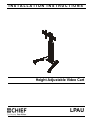
LPAU
Installation Instructions
Assembly And Installation
CAUTION: Attachment holes may be damaged if a power
drill is used to insert button head cap screws. Screws should
first be inserted and turned BY HAND with the hex key or with
a handheld screwdriver BEFORE using the head head drill bit
and power drill to complete the attachment.
Cart Assembly
1.
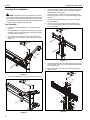
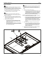
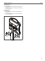
Carefully set column assembly (F) on its left side. (See
Figure 1)
2.
Place right transition cover (M) on right cart leg (J), lining up
the holes on the cover with the holes on the leg and column
assembly base. (See Figure 1)
3.
Use two 5/16-18 x 3 3/4" button head cap screws (P) to
secure leg (J) and cover (M) to column assembly (F). (See
Figure 1)
5.
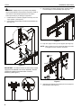
Place left transition cover (L) on left cart leg (H), lining up the
holes on the cover with the holes on the leg and column
assembly base. (See Figure 2)
6.
Use two 5/16-18 x 3 3/4" button head cap screws (P) to
secure leg (H) and cover (L) to column assembly (F). (See
Figure 2)
7.
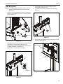
Slide interface head assembly (E) into column assembly
(F). (See Figure 3)
8.
Use four 5/16-18 x 3/4" button head cap screws (N) to
secure interface head assembly (E) to column assembly
(F). (See Figure 3)
8
(N) x 4
(E)
(rear view)
(P) x 2
3
7
(F)
(J)
(M)
2
Figure 3
9.
1
(F)
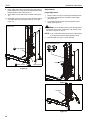
Use remaining 5/16-18 x 3/4" button head cap screw (N) to
secure column upper cover (C) to interface head assembly
(E). (See Figure 4)
10. Snap column inner cover (D) onto column assembly (F).
(See Figure 4)
9
Figure 1
4.
(N)
Turn column assembly (F) onto its right side. (See Figure 2)
(C)
(P) x 4
6
(E)
(H)
5
(D)
(L)
4
10
(F)
10
(F)
Figure 2
6
Figure 4