1
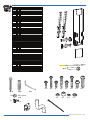
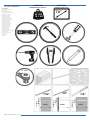
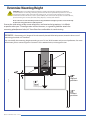
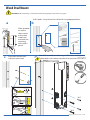
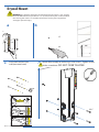
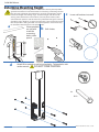
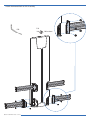
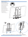
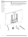
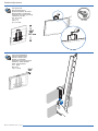
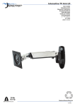
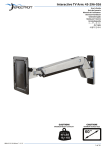
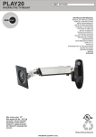
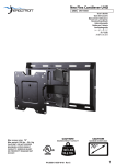
Glide Wall Mount HD User's Guide Guía del usuario Manuel de l’utilisateur Benutzerhandbuch Gebruikersgids Guida per l’utente Användarguide ユーザーガイド 用户指南 사용자 안내서 CAUTION! MAXIMUM WEIGHT CAPACITY 40 LBS 18.1 KG 888-61-015-W-01 rev. C • 01/13 CAUTION! MAXIMUM SCREEN SIZE 70" 1 of 14 Screws / Hardware for Flat Panel Part # Qty Description M-A 4 Philips screws M4 x 15mm M-B 4 Philips screws M4 x 30mm M-C 4 Philips screws M5 x 15mm M-D 4 Philips screws M5 x 30mm M-E 4 Philips screws M6 x 15mm M-F 4 Philips screws M6 x 30mm M-G 4 Philips screws M8 x 15mm M-H 4 Philips screws M8 x 30mm M-I 4 Round Spacers: M6-M8 x 5mm M-J 4 Round Spacers: M6-M8 x 10mm M-K 4 Round Washers: M4-M5 M-L 4 Round Washers: M6-M8 Wall Kit Part # Qty Description W-A 4 Lag Bolts (8mm x 80mm) W-B 4 Wall Anchor (10mm OD x 8mm ID) W-C 4 1/4-20 x 1-1/2" Hex Socket Screws Specialty Hardware Part # Qty Description P-A 16 Button Head Screw M6X6mm P-B 1 4mm Allen Wrench P-C 2 Knob Screws M4x0.7" Cable Management/Hollow Wall Description Cable Clips Cable Tubing Cable Ties Snap Toggles Contents Part # Qty Description 1 2 Verrical Rails 2 4 Horizontal Rails 3 2 Tilt Tension Knob 4 1 Lift Assembly 5 1 Wall Template Screws / Hardware for Flat Panel (PN: 697-613) Part # Qty Description M-A 4 Philips screws M4 x 15mm M-B 4 Philips screws M4 x 30mm M-C 4 Philips screws M5 x 15mm M-D 4 Philips screws M5 x 30mm M-E 4 Philips screws M6 x 15mm M-F 4 PhilipsM6 screws M6 x 30mm x 6mm 16x M-G W-A 4 Philips W-B screws M8 x 15mm P-B M-H 4 Philips screws M8 x 30mm M-I 16x 4 Round M6 Spacers: M6-M8 x 5mm M4 xx 6mm 8mm 8x M-J 4 Round Spacers: M6-M8 x 10mm P-A M-K 4 Round Washers: M4-M5 M-L 2x 4 Round M4 Washers: x 8mmM6-M8 8x P-C W-C M-A M-B M-C M-I M-D M-J M-E M-F M-K M-G M-H M-L 2x 2 of 14 888-61-015-W-01 rev. C • 01/13 CAUTION! TOOLS NEEDED MAXIMUM WEIGHT CAPACITY Tools Needed Herramientas necesarias Outils requis Benötigte Werkzeuge Benodigde gereedschappen Strumenti necessari Potrzebne narzędzia Potřebné nástroje Szükséges eszközök Απαιτούμενα εργαλεία Ferramentas necessárias Nødvendigt værktøj Tarvittavat työkalut Verktyg som krävs Instrumente necesare Необходими уреди Vajalikud tööriistad Nepieciešamie rīki Reikalingi įrankiai Potrebno orodje Potrebné náradie Необходимые инструменты Gerekli Aletler Nødvendige verktøy ةمزاللا تاودألا 需要的工具 必要なツール CAUTION! MAXIMUM SCREEN SIZE 70” 40 LBS 18.1 KG 13 mm 3/8” 7/32” 80mm 3/8” 9.5-10mm 3/8” 9.5-10mm 7/32” 5.5mm 888-61-015-W-01 rev. C • 01/13 80mm 3/8” 80mm 3 of 14 Attach Vertical Rails to your TV or or M-A M-B or M-D M-F 6mm M-L or or M-G M-H 4 of 14 6mm or or M-C M-E M-I M-J M-K or 6mm Attach monitor using monitor hardware, M-A, M-B, etc… Coloque la pantalla utilizando los materiales de instalación de la pantalla, M-A, M-B, etc… Installer le moniteur avec les fixations de moniteur, M-A, M-B, etc… Bringen Sie den Bildschirm mit den Bildschirm-Befestigungsteilen M-A, M-B usw. an. Bevestig monitor via monitor hardware, M-A, M-B, enz… Fissare il monitor utilizzando i componenti di montaggio, M-A, M-B, ecc… Zamontuj monitor, używając narzędzi dołączonych do monitora, M-A, M-B, itp… Připevněte monitor pomocí k tomu určených dílů, M-A, M-B, apod. Szerelje fel a monitort az M-A, M-B stb. monitorszerelvénnyel… Τοποθετήστε την οθόνη με το υλικό οθόνης, M-A, M-B, κ.λπ… Prender o monitor utilizando o equipamento do monitor, M-A, M-B, etc.… Påsæt skærm ved hjælp af skærm-hardware, M-A, M-B osv... Kiinnitä näyttö käyttämällä näytön osia, M-A, M-B jne. Fäst bildskärm genom att använda bildskärmshårdvara, M-A, M-B, etc... Ataşaţi monitorul utilizând structura hardware pentru monitor, M-A, M-B etc… Прикачете монитора, като използвате хардуер за монитор, M-A, M-B и др.… Kinnitage ekraan ekraani paigaldusosade abil, M-A, M-B jne… Piestipriniet monitoru,izmantojot monitora detaļas, M-A, M-B utt. Pritvirtinti monitorių naudojant monitoriaus aparatūrą, M-A, M-B ir t.t. Pritrdite monitor s pomočjo kovinskih delov za monitor, M-A, M-B itd.… Pripevnite obrazovku pomocou na to určených dielov, M-A, M-B atd. Прикрепите монитор с помощью крепежа для монитора, M–A, M–B, и т. д. Monitör donanımı, M-A, M-B vb. kullanarak monitörü takın… Fest skjermen med skjermdelene M-A, M-B etc... باقرملا تامزلتسم مادختساب باقرملا طبرا، M-A، M-B, خلا. 使用显示器硬件 M-A、M-B 等联接显示器 モニタハードウェア、M-A、M-Bなどを使って、モニタを取り付けます。 888-61-015-W-01 rev. C • 01/13 Determine Mounting Height CAUTION: Before proceeding with this installation consult your TV product guide for manufacturer recommendations on choosing a mounting location that will ensure optimum TV performance. Location considerations might include: TV height and viewing angle - based on height and distance of seating, room dimensions and size of TV; access to power outlets; cable connections for speakers and other devices; protection from glare and heat, (windows, lamps, fireplace, air ducts) and vibration. Please take into account that this product is being installed in it’s highest position. Your TV will only be able to be lowered from it’s installed position. Due to the wide variety of flat screen televisions and interior design options, it is dificult to predict what your TV configuration will be. However, as a general guideline attach the mounting plate(bottom holes) 42" from floor for comfortable sit-stand viewing. EXAMPLE: If mounting a 55” diagonal TV with centrally located VESA hole pattern, locate the lowest set of mounting plate holes 42” from floor. You can modify the mounting height according to your TV size, VESA location and personal preference. For more information, please contact Ergotron Customer Care at 800-888-8458, www.ergotron.com lowest mounting plate hole location Highest position Travel down from mounting height Lowest position 888-61-015-W-01 rev. C • 01/13 5 of 14 Wood Stud Mount CAUTION: Before mounting, read "Determine Mounting Height" Instructions on page 5! Drill 4 holes: 2 at stud and 2 at solid wall using appropriate bits. a b Place template on wall so that it covers at least one wood stud and mark the mounting holes with a pencil. c 7/32” 80mm d Insert wall anchors into wall (not wood stud). Attach lift assembly to wall using 1/4-20 screws and lag bolts. Tighten bolts with socket wrench and screw driver. DO NOT 1 1/2" diameter 1/2” OVER TIGHTEN 2 13 mm 3 1/2 pulg. de dia. 1/2" diameter 1/2 pulg. de dia. eter hole. Hold flat alongside nd slide channel jero de 1/2 pulg. ostenga la ica a lo largo de as y deslícela a straps 6between ero. 14 refingerof and ou until channel hind wall. Slide Drill 2 1/2" diameter hole. Hold metal channel flat alongside plastic straps and slide channel through hole. Taladre un agujero de 1/2 pulg. de diámetro. Sostenga la canaleta metálica a lo largo de las tiras plásticas y deslícela a Hold of straps between 3 ends través del agujero. thumb and forefinger and pull toward you until channel rests flush behind wall. Slide plastic cap along straps with other hand until flange of cap is flush with wall. Sostenga las puntas de las Snapentre strapssus at dedos wall bypulgar pushing tiras e side toyside, snapping off índice tire de ellas hacia strapshasta level with flange of cap. usted que la canaleta Hold 3 ends of straps between thumb and forefinger and pull toward you until channel rests flush behind wall. Slide plastic cap along straps with other hand until flange of cap is flush with wall. Sostenga las puntas de las Snap strapssus at wall by pulgar pushing tiras entre dedos e side to yside, off índice tire snapping de ellas hacia straps level with flange of cap. usted hasta que la canaleta quede al detrás la Rompe lasras tiras en lade pared pared. Con la otra mano, empujándolas de lado a lado, deslice lalas tapa plástica a lo soltando tiras que queden largo al niveldedelas la tiras bridahasta de laque tapa.la brida de la tapa quede al ras de la pared. Snap straps at wall by pushing side to side, snapping off straps level with flange of cap. Rompe las tiras en la pared empujándolas de lado a lado, soltando las tiras que queden al nivel de la brida de la tapa. W-C W-A 888-61-015-W-01 rev. C • 01/13 Drywall Mount WARNING: This product should only be mounted to Drywall that is >5/8" (16mm) thick. DO NOT mount this product to <1/2" (13mm) thick Drywall. Failure to follow this warning will result in an unstable attachment and may cause equipment damage or personal injury. a b 1/2” c d Insert wall anchors into wall (not wood stud). 1 1/2" diameter Attach lift assembly to wall using1/4-20 screws. Tighten screws with a screwdriver. DO NOT OVER TIGHTEN 2 3 1/2 pulg. de dia. Drill 2 1/2" diameter hole. Hold metal channel flat alongside plastic straps and slide channel through hole. Taladre un agujero de 1/2 pulg. 1/2 pulg. de dia. de diámetro. Sostenga la canaleta metálica a lo largo de las tiras plásticas y deslícela a hole. Hold Hold of straps between 3 ends través del agujero. alongside thumb and forefinger and lide channel pull toward you until channel rests flush behind wall. Slide plastic cap along straps with de 1/2 pulg. other hand until flange of cap nga la is flush with wall. a lo largo de 888-61-015-W-01 rev. C deslícela a Sostenga las• 01/13 puntas de las ps between Snapentre strapssus at dedos wall bypulgar pushing tiras e nger and side toyside, snapping off índice tire de ellas hacia until channel usted strapshasta level with flange of cap. que la canaleta d wall. Slide 1/2" diameter Hold 3 ends of straps between thumb and forefinger and pull toward you until channel rests flush behind wall. Slide plastic cap along straps with other hand until flange of cap is flush with wall. Sostenga las puntas de las Snap strapssus at wall by pulgar pushing tiras entre dedos e side to yside, off índice tire snapping de ellas hacia straps level with flange of cap. usted hasta que la canaleta quede al detrás la Rompe lasras tiras en lade pared pared. Con la otra mano, empujándolas de lado a lado, deslice lalas tapa plástica a lo soltando tiras que queden largo al niveldedelas la tiras bridahasta de laque tapa.la brida de la tapa quede al ras de la pared. Snap straps at wall by pushing side to side, snapping off straps level with flange of cap. Rompe las tiras en la pared empujándolas de lado a lado, soltando las tiras que queden al nivel de la brida de la tapa. W-C 7 of 14 Solid Wall Mount Determine Mounting Height CAUTION: Before proceeding with this installation consult your TV product a guide for manufacturer recommendations on choosing a mounting location that will ensure optimum TV performance. Location considerations might include: TV height and viewing angle - based on height and distance of seating, room dimensions and size of TV; access to power outlets; cable connections for speakers and other devices; protection from glare and heat, (windows, lamps, fireplace, air ducts) and vibration. Please take into account that this product is being installed in it’s highest position. Your TV will only be able to be lowered from it’s installed position. Place template on wall and mark the mounting holes with a pencil. b c Insert wall anchors into wall. Drill 4 holes. 4x 3/8” W-B 80mm d Attach lift assembly to wall using lag bolts. Tighten bolts with socket wrench. DO NOT OVER TIGHTEN 13 mm 4x W-A 8 of 14 888-61-015-W-01 rev. C • 01/13 Attach Horizontal Rails to Lift Assembly P-B P-A 16x M6 x 6mm 8x M4 x 8mm 2x 888-61-015-W-01 rev. C • 01/13 9 of 14 Hang the TV on the Lift Assembly Hang with monitor attached Cuelgue con el monitor adherido. Accrochez avec le moniteur installé. Mit dem befestigten Monitor aufhängen. Hang op terwijl de monitor is bevestigd. Appendere con lo schermo attaccato. Powieś z przymocowanym monitorem. Zavěste s připevněným monitorem. Függessze fel a monitorral együtt. Κρεμάστε με την οθόνη προσαρτημένη Suporte com monitor preso Hæng op med skærm påsat Ripusta näyttö kiinnitettynä Häng med bildskärm fastsatt Agăţaţi cu monitorul ataşat Закачи с монитора прикрепен Riputage koos kinnitatud ekraaniga Piekārt ar pievienoto monitoru Pakabinti su pritvirtintu monitoriumi Obesite s pritrjenim monitorjem Zaveste s pripevnenou obrazovkou. Навесьте с установленным монитором. Takılı monitörle asın Heng med skjermen festet ًاطوبرم باقرملاو قيلعتلاب مق 在显示器已联接的条件下悬挂 モニタを取り付けた状態で掛けます。 M6 x 6mm 16x 8x P-C M4 x 8mm 2x NOTE: For safe and proper installation be sure to install the locking screw as shown. 10 of 14 888-61-015-W-01 rev. C • 01/13 Route Cables Route Cables Tienda los cables Installez les câbles Verlegen Sie die Kabel Plaats de kabels Inserire i cavi Poprowadź kable Natáhněte kabely Vezesse el a kábeleket. Δρομολόγηση καλωδίων Dispor os cabos Føringskabler Reititä kaapelit Lägg kablar Direcţionaţi cablurile Маршрутни кабели Suunake kaablid oma kohale Virzienu kabeļi Kabelių išvedžiojimas Napeljava kablov Natiahnite káble Укладка кабелей Kabloları Düzenleyin Før kablene تالبكلا هيجوت 布线 ケーブルを配線します 888-61-015-W-01 rev. C • 01/13 Use the below items to appropriately route your power, hdmi, and AV cables. Be aware of pinch points when routing cables. To avoid possible cable damage, only use cable clips on the outside edge othe TV. 11 of 14 It is important that you adjust this product according to the weight of the mounted equipment as described in the following steps. Any time equipment is added or removed from this product, resulting in a change in the weight of the mounted load, you should repeat these adjustment steps to ensure safe and optimum operation. • Adjustments should move smoothly and easily through the full range of motion and stay where you set it. If adjustments are difficult and do not stay in the desired position, follow the instructions to loosen or tighten the tension to create a smooth, easy adjustment motion. Depending on your product and the adjustment, it may take several turns to notice a difference. Es importante ajustar este producto conforme al peso del equipo montado, según se describe en los pasos siguientes. Cada vez que se agregue o quite equipo de este producto y cambie el peso de la carga montada, deberá repetir estos ajustes para garantizar un funcionamiento seguro y óptimo. • Los movimientos de ajuste deben poder realizarse de manera suave y firme dentro de la amplitud de movimiento permitida, y mantenerse donde usted los fije. Si los ajustes son abruptos o no permanecen en dicha posición, siga las instrucciones para aflojar o ajustar la tensión y suavizar así el movimiento. Dependiendo del producto y el ajuste, es posible que deba hacer varios intentos hasta poder observar la diferencia . Il est important que vous fixiez ce produit par rapport au poids du matériel installé, comme l’indiquent les étapes suivantes. À chaque fois que vous ajoutez ou que vous retirez du matériel de ce produit, et que le poids du matériel change, répétez ces étapes d’ajustement pour garantir la sécurité et une utilisation optimale. • Les réglages doivent s'effectuer facilement et sans forcer dans toutes les positions et rester en place une fois réalisés. Si les réglages sont difficiles à effectuer et ne restent pas en position, suivez les instructions pour desserrer ou resserrer la tension afin que les mouvements soient plus aisés. Selon le produit que vous utilisez et le réglage, il faut parfois effectuer plusieurs tours de vis avant de remarquer une différence. Es ist von Bedeutung, dass Sie dieses Produkt entsprechend dem Gewicht des installierten Geräts wie in den folgenden Schritten beschrieben anpassen. Wenn Zubehör von diesem Produkt entfernt oder dazu hinzugefügt wird, was zu einer Änderung der Last führt, sollten Sie diese Einstellungsschritte wiederholen, um einen sicheren und optimalen Betrieb zu gewährleisten. • Einstellungen sollten über den gesamten Verstellbereich gleichmäßig und leicht durchzuführen sein und an der eingestellten Position verbleiben. Lassen sich die Einstellungen nur schwer durchführen oder bleibt das Gerät nicht in der gewünschten Position, folgen Sie der Anleitung und lockern oder verstärken Sie die Spannung für eine gleichmäßige und leichte Einstellung. Je nach Produkt und Einstellung muss dies mehrmals wiederholt werden, um einen Unterschied zu merken. Het is belangrijk dat u dit product aanpast volgens het gewicht van de gemonteerde apparatuur zoals beschreven staat in de volgende stappen. Telkens als er apparatuur toegevoegd wordt aan of verwijderd wordt van dit product, wat een verandering van het gewicht van de gemonteerde belasting tot gevolg heeft, moet u deze aanpassingsstappen herhalen om een veilige en optimale werking te garanderen. • Verplaatsingen moeten soepel en eenvoudig over het volle bewegingsbereik mogelijk zijn, en de ingestelde positie moet gehandhaafd blijven. Als aanpassingen moeilijk zijn en de gewenste positie blijft niet gehandhaafd, dan volgt u de instructies om de spanning te verminderen of vergroten om een soepele, eenvoudige aanpassing mogelijk te maken. Al naargelang uw product en de gewenste aanpassing, kunnen een paar slagen nodig zijn om verschil te merken. È importante regolare questo prodotto in base al peso dell'attrezzatura montata, come descritto nella procedura seguente. Ogni volta che si aggiungono o si rimuovono componenti da questo prodotto, variando quindi il peso del carico fissato, ripetere questa procedura di regolazione per garantire il funzionamento ottimale e in sicurezza • I componenti a posizione regolabile devono essere spostabili in modo regolare e agevolmente per la loro intera corsa e rimanere fermi quando li si rilasciano. Se risulta difficile regolare la posizione di un componete o questo non rimane nella posizione desiderata, seguire le istruzioni per ridurre o aumentare la tensione di bloccaggio affinché il movimento risulti agevole e facilmente regolabile. A seconda del prodotto e del tipo di regolazione, possono essere necessarie più corse prima di notare una differenza. Det är viktigt att du justerar denna produkt enligt den monterade utrustningens vikt, som beskrivet i följande steg. När utrustning läggs till eller tas bort från denna produkt och vikten av den monterade belastningen förändras, bör du upprepa dessa justeringar för att säkerställa säker och optimal drift. Justeringar ska röra sig smidigt och lätt genom hela uppsättningen rörelser, och stanna där du ställer in dem. Om justeringarna är besvärliga och inte stannar i önskad position, följ instruktionerna om att lossa på eller skruva åt skruvar för att skapa en smidig och lätt justeringsrörelse. Beroende på din produkt, och på justeringen, kan det ta flera varv innan man märker någon skillnad. この 製品は、取り付けた機器の重量に応じて次の手順で調整してください。 この製品に機器を取り付けたり、取り外したりして重量が変わ った場合は、安全かつ最適な操作を保証するために同じ手順をふたたび実行してください。 調整は可動域内でスムーズかつ簡単に動く必要があり、選定した位置にしっかり固定されなければなりません。調整の動きがぎこちなく、選 定位置で固定されない場合は、調整がスムーズにできるよう、説明書に従って張力を増減します。お使いの製品や調整によっては、違いがは っきりするまで何回か回さなければならないこともあります。 调节应当能在整个动作范围内灵活自如,并能固定在所调整的位置。如果调节困难且不能固定在想要的位置上,请遵照说明书拧松或拧紧,使调 节动作灵活自如。根据您所用产品及调节方式,可能需要旋转几圈后才能注意到差别。 12 of 14 888-61-015-W-01 rev. C • 01/13 Product Adjustments a Lift – Up and down Elevación (arriba y abajo) Ajustement en hauteur : bas et haut Höhenverstellung – rauf und runter Verstel in hoogte – Omhoog en omlaag Sollevamento – Su e Giù Lyft – upp och ned リフト(上下) 升降(上下) 높이 (위/아래로) 13 mm 18" 457 mm b Tilt – Forward and Backward Inclinación (adelante y atrás) Inclinaison : Avant et arrière Neigung – vor und zurück Kantel – Naar voren en naar achteren Inclinazione – Avanti ed Indietro Vinkla – framåt och bakåt チルト (前後) 倾斜(前后) 기울기 – 앞/뒤로 10° 888-61-015-W-01 rev. C • 01/13 13 of 14 14 of 14 888-61-015-W-01 rev. C • 01/13