1
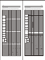
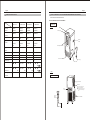
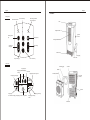
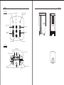
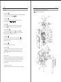
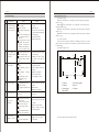
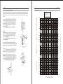
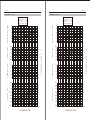
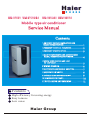
Haier
HM-07C03 HM-07C03/R1
HM-09CA03 HSM-08C03
Mobile type air conditioner
Service Manual
Contents
1.PRODUCT CODE ILLUMINATION AND
SERIES INTRODUCTION....................................... 1
2.
........................ 2
3.PRODUCT SPECIFICATION................................... 3
4.MAIN COMPONENTS AND ACCESSORIES
NAME, DIMENTION AND FUNTION....................
4
5.
......................................................
5
6.WIRING DIAGRAM................................................ 6
7.
.................. 7
8.SYSTEM FLOW CHART........................................ 8
9.INSTALLATION AND REPAIRING ...................... 9
10.SYSTEM FLOW CHART........................................ 10
11.INSTALLATION AND REPAIRING ...................... 11
Features
High efficiency for saving energy
Easy to move
Low noise
Haier Group
CATALOGUE
Haier
Mobile Type Conditioner Technical Manual
¼
¼
Ê
õ
Ê
Ö
²
á
1
PRODUCT CODE ILLUMINATION AND SERIES INTRODUCTION
1
2
PRRODUCT TECHNICAL PARAMETER
2
3
PRODUCT SPECIFICATION
3
4
MAIN COMPONENTS AND ACCESSORIES'NAME,
DIMENTION AND FUNTION
4
Model:
5
KNOCK-DOWN DRAWING AND LIST OF COMPONENT
5
6
MICROCOMPUTER CONTROLING
6
7
THE FUNCTION OF ELECTRIC CONTROL INTRODUCTION
7
8
WIRING DIAGRAM
8
9
MAINTENANCE ANDTROUBLE SHOOTING
9
HM 07C03 HM 07C03/R1 HM 09CA03 HSM 08C03
10
SYSTEM FLOW CHART
11 INSTALLATION AND REPAIRING
10
11
Page 11
Page 2
1.RODUCT CODE ILLUMINATION AND SERIES INTRODUCTION
b
Standard situation/conditions
a model code rule description
No.
1.1Model identification:
H S M
A BC
D
E
F
G
H
A:Abbreviation of Haier
B:Abbreviation of Split
C:Abbreviation of Mobile
D:Nominal cooling capacity(BTU/h)with the fitst two numbers based on one
thousand unit
E:Function code
C-Cooling only
H-Heating pump
E-Electric aided heating
F:Developing sequence
G:The type of power supply
H:The kind of refrigerant
Examples:
Hsm-08C03
-It represents Split-Mobile air conditioner.Cooling capacity is 8000
BTUh and the power supply is 200~230V/50Hz.
C
Indoor air state
Operating condition
outdoor air state
D. B.
W. B.
D. B.
W. B.
1
Nominal cooling
30
26
30
26
2
Nominal heating
/
/
/
/
3
Nominal electrical
heating
/
/
/
/
Brief introduction of mobile window air conditioner series
The product of mobile air conditioner is the now type of air conditioner developed by our company, its main
character is:there aie four foot wheels in the botton of indoor unit, which can move among each apartment of the
room. For whole mobileair conditioner suchas HM-07C03, HM-07C03/R1, HM-09CA03, hat between indoor unit
and outedoor unit can be exchanged through wind pipe, for split-mobile air conditioner such ad HSM-08C03, heat
can be exchanged through outdoor unit. Drainage of mobile air conditioner use the principle of gravity drainage,
having the cooled water flown into water tank,pour it out when the tank is full. This type of product have the
advantage of easy installation without breaking the wall, so it is very popular with many consumers.
Page 3
Page 4
PRODUCT SPECIFICATIONS
PRODUCT SPECIFICATIONS
The manufactur reserves the right to change any change any product specifications without notice.
Item
Cooling capacity
Heating capacity
Power supply
Power factor
UNIT
BTU/h
BTU/h
Power input
Running current
EER
Power input
Running current
COP
Indoor side
Outdoor side
Height
Width
Depth
Height
Width
Dpth
Net
Gross
Type
Model
Heating side
Cooling side
Model
charge
Cooling
Heating
Sund Leval
Case
Packaging
dimensions
Weight
Compressor
Pressure
Refrigerant
Type
Fan
Fan speed
indoor unit
outdoor unit
Hi
Lo
Air direction control
Air volume Monisture removal
Moisture removal
Attestation
Compressor oil charge
Exchanging pipe type/diameter
Fin factor
Fin material
Case material
Type of capillary
Total area of evaporator
Total area of conenser
Pipe connection
%
W
A
BTU(hW)
W
A
BTU(hW)
dB(A)
dB(A)
mm
mm
mm
mm
mm
mm
kg
kg
MPa
MPa
kg
r/min
m3/hr
m3/hr
ml
mm
mm2
mm2
HAM-08C03
HM-09CA03
8000
900
/
/
1PH,220~50Hz
1PH,220~50Hz
0.96
0.94
880
1100
4.6
5.3
8.6
8.2
/
/
/
/
/
/
50
50
/
/
326
326
788
788
430
430
415
415
857
857
495
495
33
33
37
53
TOSHIBA
TOSHIBA
PH150X1C-4DZ2(2000165) PH165X1C-4DZ2(2000165)
2.65
2.65
2.65
2.65
R22
R22
0.75
0.6
inertialfan
inertialfan
Axial fan
/
1140
1140
1070
1070
60~70
60~70
260
260
-3
1.6 10
1.6 10-3
CE
CE
400
400
evaporator: 7condenser: 9 evaporator: 7condenser: 9
/
/
Hydrophile aluminum foil
Hydrophile aluminum foil
Electrial zine board
Electrial zine board
1.2TP2Y
1.2TP2Y
2.02
2.28
4.67
5.26
/
/
The manufactur reserves the right to change any change any product specifications without notice.
Item
Cooling capacity
Heating capacity
Power supply
Power input
Cooling
Running current
EER
Power input
Heating
Running current
COP
Indoor side
Sund Leval
Outdoor side
Height
Case
Width
Depth
Height
Packaging
Width
dimensions
Dpth
Net
Weight
Gross
Type
Model
Compressor
Running cap. for
comp.
Starting method
Heating side
Pressure
Cooling side
Model
Refrigerant
charge
indoor unit
Type
outdoor unit
Fan
Fan speed Hi
Lo
Running capacitor
Air direction control
Air volume Monisture removal
Moisture removal
Attestation
Compressor oil charge
Exchanging pipe type/diameter
Fin factor
Fin material
Case material
Type of capillary
Total area of evaporator
Total area of conenser
Pipe connection
UNIT
BTU/h
BTU/h
W
A
BTU/(hW)
W
A
BTU/(hW)
dB(A)
dB(A)
kg
kg
F
MPa
MPa
kg
r/min
r/min
F
m3/hr
m3/hr
ml
mm
mm2
mm2
HAM-07C03
HM-07C03/R1
7000
7000
/
/
1PH,220~50Hz
1PH,220~50Hz
800
800
4.3
4.3
8.7
8.8
/
/
/
/
/
/
50
50
/
/
326
326
788
788
430
430
415
415
857
857
495
495
32
32
34
34
TOSHIBA
TOSHIBA
PH135X1C-4DZ2(2000165) PH135X1C-4DZ2(2000165)
25
25
PSC
2.65
0.65
R22
0.52
inertial fan
/
1070
1140
30
60~70
260
1.6 10-3
CE
400
evaporator: 7
: 9
/
Hydrophile aluminum foil
Electrial zine board
1.2TP2Y
1.77
4.09
/
PSC
2.65
0.65
R407C
0.6
inertial fan
/
1070
1140
30
60~70
260
1.6 10-3
CE
400
evaporator: 7
: 9
/
Hydrophile aluminum foil
Electrial zine board
1.2TP2Y
1.77
4.09
/
Page 5
Page 6
3 PRODUCT SPECIFICATION
4
MAIN COMPONENTS AND ACCESSORIES'NME,DEMENTION AND FUNTION
HM-07C03, HM-07C03/R1,HM-09CA03
MAIN COMPONENTS AND ACCESSORIES
HM-07C03
HM-07C03/R1
HM-09CA03
Machine body
HSM-08C03
Structural
Mobile air
Mobile air
Mobile air
Mobile air
faeature
conditioner
conditioner
conditioner
conditioner
cooling
7000BTU/h
7000BTU/h
9000BTU/h
8000BTU/h
220V
220V
220V
220V
Mobile air
Mobile air
Mobile air
Mobile air
conditioner
conditioner
conditioner
conditioner
series
series
series
series
attestation
CE
CE
CE
CE
remote
No
No
No
No
refrigerant
R22
R407C
R22
R22
Climate type
T1
T1
T1
T1
dimensions
430
Front
LCD
Control panel
capacity
voltage
Type
of
product
Handle
buckle
Vertical pendulum blade
Apppeatance
feature
326
788mm
430
326
788mm
430
326
788mm
430
Gaster wheel
Power pulg
326
mm(
packege
547
dimensions
Box up
document
499
1147
547
mm
No
499
1147
547
mm
No
499
1147
547
No
)
1147
mm(
mm
No
499
Water tank
788
)
Bacl
Hot air exhaust duct
Top air intake bar
Water exit
Use to connect the drainage
Hot air
exhaust exit
Accessories
of hot air
exhaust duct
Do not pull out-this part
When the drainage is not used
or it may result in leakage of
water
Low air intake bar
Page 7
Page 8
HSM-08C03
Control panel
The running indicator
of the compressor
Fan selection key
Water full indicator
LCD
Impeller inducer
OPERATION
WATER FULL
Running mode
key
Handle
buckle
Sweeping key
MODE
Temperaure
setting key
FAN SPEED
Vertical pendulum blade
LOUVER
Time setting
key
SLEEP
TEMP SET
ON/OFF
Gaster wheel
TIME SET
Sleep setting key
Power plug
Water tank
Power switch.key
LCD windo
Connecting pipe
Displaying of
Displaying of dehumidifying
Cooling
Air filter
Handle
Fan mode
Displaying of the tan speed
Air outlet(outdoor)
Air outlet
(indoor)
Displaying of sleeping
FAN SPEED
SET TMEP
88
ON
C
Displaying
of automatic sweeping Displaying of the set temperaaure
OFF
88
Hr
Handle
Displaying of timing
Displaying of timing
mode
Foot wheel
9
10
Control panel
433
795
Water full indicator
OPERATION
WATER FULL
Running mode
key
Sweeping key
MODE
Temperaure
setting key
FAN SPEED
LOUVER
Time setting
key
SLEEP
TEMP SET
ON/OFF
TIME SET
Sleep setting key
Power switch.key
LCD windo
Displaying of
Displaying of dehumidifying
Cooling
Fan mode
Displaying of the tan speed
Displaying of sleeping
FAN SPEED
SET TMEP
88
328
The running indicator
of the compressor
Fan selection key
ON
C
Displaying
of automatic sweeping Displaying of the set temperaaure
OFF
88
Hr
Displaying of timing
Displaying of timing
mode
Page 11
FUNCTION
Page 12
KNOCK-DOWN DRAWZIN AND ITST OF COMPONENT
HM-07C03, HM-07C3/R1,HM-09CA03
1.Running Mode Key
press the key to choose from three running node:cooling mode:cooling dehumidifying Fan.The
LCD window displays correspondingly:
2.Fan Seletion Key
Press the key to choose from three fan speed:high middle low.The LCD windo
displays correspondingly:
3.Sweep key:
Press the key to enable automatic side-to-side sweeping of the indoor air.The LCD
window displays
;press the key again to fix the indoor air at present direction.
4.Temperarure Setting key
Press the key to set the temperarure between 10-30 .Each press of the part will
increase the remperarure for 1 each pressg of the part will decrease the temperarure
for 1 .The temperature will be displayed in the LCD window.
5.Sleep Setting key
Press the key to set or cancel Sleep Mode.When the LCD window displays
the air
conditioner is nuder Sleep Mode.Press again to cancel the Sleep Mode,and the signal
will disappear on the LCD indow.
6.Power Switch key
Power Switch on/off the power of the air conditioner.
7.Time Setting key:
Press the key to set or cancel the Time Mode,or set rime berween1-24hours.Each press
of the part will add one hour. which will be displayed on the LCD window, each
pressing of the part will reduce one hour, If it shows 1 hour.Press once to cancel the
timing.
8.Water Full indicator of:
When the water rank is filled with water, the indicator will flash,and alarm iwth veep.The
compressor stops working.The air conditioner enrers fan mode.Please take our the water
tank. Pour the condensed water, then replace it. The air conditioner runs as per the mode
vefore stopping of the compressor(the compressor can only start after 3 minutes of
time-delay protection).
9.The run indicator of the compressor:
In cooling or dehumidifying mode, the indicator will be on in the running of the compressor.
Page 13
Page 14
Model:HM-09CA03
Model:HM-07C03/R1
Special
N
NO.
O.
Name
Quantity
1
0400080
1
2
3
4
5
6
7
8
9
10
11
12
13
14
15
16
17
1231144
1301332
1231149
0400081
1301331
2000119
5102034
1754742
1101099
1431503
1231148
2111740
2111737
1231142
0100278
1431507
18
19
20
21
22
23
24
25
26
27
28
29
1231145
3400064
1436506
1101086
1101088
1231158
1101089
1231157
1231147
1231160
1231146
1231153
30
31
32
33
34
35
36
3000079
3600142
1301330
1231145
1301338
1436499
1231152
Evaporator
Assembly
Side plate,left
Draw board
Indoor intake bar
Condenser assembly
Support bar
Compressor
Nut special
Cushion rubber
Bottom plate
Wheel
Rear panel
Discharge pipe
Suction pipe
Front plate
Front panel
Storage tank base
board
Storage tank
Micro switch
Strong tank cover
Partition plate assy
Protective plate
Drain pan
Cover
Vendiduct(outdoor)
Cover panel
Outside fan
Cover
Vendiduct
cover(outdoor)
Motor(down)
Compressor capacitor
Capacitor clamp
Side plate right
Support plate
Drain pan
Vendiduct
(indoor,down)
Inside fan
Vendiduct
(indoor,up)
Electric board
Tronsormer
37 1231159
38 3800063
39 3300092
40 3000078
A
41 3600096
42 3000078
43 3600096
44 3600018
A
Control board
Motor(up)
Fan capacitor
Motor capacitor
1
2
1
1
4
1
3
3
1
4
1
description
Damageable
parts(yes or
no)
No
Special
N
NO.
O.
Name
Quantity
1
0400080
1
No
No
No
No
No
Yes
No
No
No
No
No
No
No
No
No
No
2
3
4
5
6
7
8
9
10
11
12
13
14
15
16
17
1231144
1301332
1231149
0400081
1301331
2000119
5102034
1754742
1101099
1431503
1231148
2111740
2111737
1231142
0100278
1431507
No
No
No
No
No
No
No
No
No
No
No
No
18
19
20
21
22
23
24
25
26
27
28
29
1231145
3400064
1436506
1101086
1101088
1231158
1101089
1231157
1231147
1231160
1231146
1231153
Yes
No
No
No
No
No
No
No
No
No
No
No
No
30
31
32
33
34
35
36
3000079
3600142
1301330
1231145
1301338
1436499
1231152
Evaporator
Assembly
Side plate,left
Draw board
Indoor intake bar
Condenser assembly
Support bar
Compressor
Nut special
Cushion rubber
chassis
Wheel
Rear panel
Discharge pipe
Suction pipe
Front plate
Front panel
Storage tank base
board
Storage tank
Micro switch
Strong tank cover
Partition plate assy
Protective plate
Drain pan
Cover
Vendiduct(outdoor)
Cover panel
Outside fan
Cover
Vendiduct
cover(outdoor)
Motor(down)
Compressor capacitor
Capacitor clamp
Side plate right
Support plate
Drain pan
Vendiduct
(indoor,down)
Inside fan
Vendiduct
(indoor,up)
Electric board
Tronsormer
Control board
Motor(up)
Fan capacitor
Motor capacitor
No
No
Yes
Yes
Cost
price
37 1231159
38 3800063
39 3300092
40 3000078
A
41 3600096
42 3000078
43 3600096
44 3600018
A
description
Damageable
parts(yes or
no)
No
1
2
1
1
4
1
3
3
1
4
1
1
1
1
1
1
No
No
No
No
No
Yes
No
No
No
No
No
No
No
No
No
No
1
1
1
1
1
1
1
1
1
1
1
1
No
Yes
No
No
No
No
No
No
No
No
No
No
1
1
1
1
1
1
1
1
1
Yes
yse
No
No
No
No
No
No
No
No
No
No
No
1
1
1
1
No
No
Yes
Yes
1
1
Cost
price
Page15
Page 16
Exploded View
Indoor unit
26
30
31
13
32
51
52
50 49
35
34
33
36
39 40
38
37
42
41
43
44
46
48
47
45
14
15 16
17
18
19
20
29
21
28
22
23
24
25
27
08C03
1
2
5
4
3
6
7
8
9
10
11
12
HSM
Model:HM-07C03/R1
Special
N NO.
O.
Name
Quantity
description
Damageable
parts(yes or
no)
No
1
1231142
Front panel
1
2
3
4
5
6
7
8
9
10
11
12
13
14
15
16
17
18
19
20
1431496
1431498
1436497
1231143
1231146
3000092
1231146
1231149
1442517
1231144
1434516
1235168
3000078
1231154
1301330
3600142
2600141
4000120
1231153
1
2
1
1
4
1
3
3
1
4
1
1
1
1
1
1
1
1
1
No
No
No
No
No
No
No
No
No
No
No
No
Yes
No
No
Yes
Yes
No
No
21
22
23
24
25
26
27
28
29
30
1445520
1431738
4200065
1431751
1762207
2000110
1231145
1301926
1231155
1431507
1
1
1
1
1
1
1
1
1
No
No
Yes
No
No
Yes
No
No
No
No
31
32
33
34
35
36
37
38
39
40
41
42
43
1431503
1101090
1301332
1301331
1301338
1436506
1301476
3400009
1231152
1231156
1231159
1101189A
1231151
1
1
1
1
1
1
1
1
1
1
1
1
1
Yes
No
No
No
No
No
No
No
No
No
Yes
No
No
44
45
46
47
48
49
50
51
52
1445119
3800630
1439445
3000092
1436449
300084
1431550
1431513
0400080
verrical flap
connection rod
Horizontal flap
Front panel inlay
Top panel inlay
Control panel
Top panel
Indoor intake bar
filter
Left side board
Press key membrane
Cover
Upper motor
electronic
Capacitor clip
Compressor motor
Fan motor
line contact bank
scroll case cover
(outdoor unit)
Power cord clip
Rear cover
Power cord
Connecting pipe bracker
Sound absorption cushion
copmpressor
right side board
Partition panel
Water storage box
Base board of Water storage
box
Foot whell
chassis
Pulling board
Support bar
baffle
Water storage box xover
Machine hanging board
Full water switch
Scroll cover(indoor unit)
Cooled water box
Fan(indoor unit)
cover
Upper scroll cover (indoor
unit)
Water meeting pipe clip
transformer
Water meeting pipe
Control panel
Water meeting tray
Synchronous motor
Brace of Symchronotus motor
flat board of flap
condenser
1
1
1
1
1
1
1
1
1
No
Yes
No
No
No
Yes
Yes
No
Yes
Cost
price
Page 17
HSM
Page 18
08C03
Outdoor unit)
N
O.
10
4
5
6
7
8
9
11
3
Special
NO.
Name
Quantity
Description
Damageable
parts(yes or
no)
1
1436739
Inlet bars
1
No
2
1436730
Case
1
No
3
1436733
Handle holder
1
No
4
1436732
Handle abutment
1
No
5
1452737
Handle
1
No
6
0900092
Connecting pipe group
1
No
7
2336052
Axial fan
1
Yes
8
1301473
Motor holde
1
No
9
3000155
Outdoor fan
1
No
10
1101157
Connecting
1
Yes
pipe
baseboard
2
12
1
13
14
15
11
1301474
Side board
1
No
12
1436734
Condenser
1
No
13
1301474
Cord board
1
No
14
1436734
Wind circle
1
No
15
1436735
Outdoor chassis
1
No
Page 19
Page 20
THE FUNCTION OF ELECTRIC CONTROL CONTROL INTRODUCTION
Flow chart for operation
Load the subprogram of I/O sampling and process
the sampling data.
Switch on power and test
Delay for 20 ms
Hsa one
second passed?
N
Initialize the RAM
I/O port and special register
Load the subprogram of time handling,which
requires precision within one second (Such as restarting
the compressor after 3 minutes delaying etc.)
The buzzer rings twice
The LCD displays the whole screen for
2 seconds
Hsa one
second passed?
N
Clear the LCD screen
Have10
ms
passed?
N
The major loop
Load the subprogram of time handliing which requires
precision within one minute (such as the Timing on/off,
sleep,etc)
Y
Load the subprogram of LCD display
(including blade,Mode,Fand sleep,Timing and Temperature)
Is there
something wrong with
the temperarure
sensor?
Y
Has the
water been full ofr
3 minutes?
Y
Load the subprogram of keyboard processing
Load the subprogram of fast-test concluding
Have 25
ms
passed?
N
Perform the conclusion processing to show if the water
is full and if it passes for 3 minutes.
Judgement and processing of the key
value
Handle it as switching
off power
Return to the major
Loop
Page 21
Page 22
WIRING DIAGRAM
Is the conditioner
open?
N
W
Handle it as switching
off power
Y
BR
BR
BL
N
Return to the major
Loop
Power otug Y/G
L N
Is
it under
the
cooling mode?
Synchro BR
motor
BL
CN1
Y/G
Trons
PH5
W
CN4
Upper
for
moton
Y
PH1
B:Block
W:White
BR:Bnown
BL:Blue
R:Red
Y/G:Yellow/Greer
OR:Orange
Upper
for
moton
OR
PH4 PH3 PH2
73636298
Fan capocitor
BR
R
BL
PH6
R
CN2
LCD
Relay CN3
R
TH2
Fan copacitor
Is it
under dehumidifying
mode?
Waer
switch
C
N
S
W
COME
TH1
CN5
CN6
Piping tenp
Sensor
Room
temp
sensor
R
Y/G
B
B
Compressor capocitor
HM-07C03,
HM-07C03/R1,
Load the subprogram of the cooling mode
HM-09CA03
HM-07C04
WIRING DIAGRAM
Return to the major Loop
7363759
Fan motor capacitor
BR
Synchro- BR M
motor
Load the subprogram of
ventilating mode
M
BL
Pomer
BR
BL
W B BL OR
PH4 PH3 PH2
PH1
CN1
3.15A 250V-
Y/G
PH5
Y/G
Outdoor
side
W
OR
W B BL OR
Plug
BR
L N
Return to the major
loop
W
CN4
W
B
W
Fuse
Trans
BL
PH6
B
CN2
LCD
Retoy CN3
TH2
R
Outdoor
fon
motor
M
R
R
R
Fan motor
capocitor
R
CN5
Water
switch
TH1
CN6
Piping temp
Sensor
Roon temp
Sensor
Y/G
S
W
M
B
R
B
Y/G
Compressor
Copaciter
HM-08C03
R:Red
W:White
B:black
BL:Blue
BR:Brown OR:Orange
Y/G:Yellow/Green
Page 23
Page 2 4
9.Maintenance and trouble shooting
9.1.Maintenance manual
1) Functional instruction
1.Run mode:cooling dehumidifying air flowing
2.Fan adjusting:HI MID LO
3.Timing:Timing on 1-24 h
Timing on 1-24 h
4.The set temperature range:15 -30
5.Swing automatic swing or fix at a poing
6.Sleep:8 hours
2)Instruction of the run mode:
1Cooling node:
(1)The inner initialized set temperarure is 24 and the initialized fan is HI.
(2)The fan speed is adjustable, in turn of HI MID LO
(3)Asjusting of the temperature:
Each pressing of the
key will increase the set temperarute for 1 till
it reaches30 , Each pressing of the
key will decrease the set temperarure for1 ,till it
reaches 15
(4)Adjusing of the air direction:
Under the mode of inner fan running, the air direction can be adjusted by,the
synchro motor to control the starting and closing of the motor
2.Dehumidifying mode:
(1)The fan speed is not adjustable
Incase of the ambient temperarute>15 ,the fan speed is LO.and sompressor
is open;
Incase of 12
ambient temperature 15 ,the fan speed is MID,the
Compressor is open;
(2)The air direction is adjustable.
(3)The set temperarure is not adjustable.
3)Air supply mode:
(1) Water full protection
Under any node, when the water full protectuin is detected to be activated,the
buzzer will beepseveral times consecutively,and the water full alarm lamp
will flash on and off with a 0.5 second frequency.The compressor and outer fan
will stoprunning.It will enter air supply mode.The inner fanwill ren at the
former speed.If the water full protection is released in 3 minutes,the controller
will run under previous set mode and the water full alarm lamp will be off.If it
is not released in 3 minutes,. the inner fan will stop running either and whole
machine is under stand-by mode,.But the water full alarm lamp will keep on
flashing rill it is released.
2.Ppotection against freeaing
When the coildepipe temperature sensor detects that the surface temperatrue of
the avaporator T -2 ,the compressor and the fan will stop running,the inner
fan will run at HI speed and the Fan key will be impotent.When the detected
temperature>-8 amd the stop time of the compressor is longer than 3 minutes,
the compressor and the onter fan will be started and the inner fan runs at set
fan speed.
3. Prtection of the compressor
The compressor must be restarted after 3 minutes from the former stop,except
for the power failure.
5) Sleep prostection
1.the function is only activited under cooling mode, and impotent under other
modes.
2.Afer one hour running under cooling sleep, the set temperature will
rise for 1 ,and rise for another 1 after one another hour,after another6
hours of running the complete machine will be shut down.
3.In case that Sleep and Timing Off are set at the same time, the first impotent
not will be activated.
4.In Sleep mode the Timing On will be impotent.
6)Timing function
1.The timing Off can be set when the machine is rumming;the Timing On can be
set when the machine is shut down.
2.The timing range is 1-24h;
Each pressing of the
key will raise the set time for 1h;each pressing of
the
key will reduce the set rime for 1h.When it is added to 24h the
key or
key will cancel the timing.
Page 25
Page 26
10 SYSTEM FLOW CHART
9.2 Trouble shooting
No.
Phenomenon
1
The complete machine
does not start without
any reflection after the
power is switched on
2
3
The LCD displays, but
the complete machine
can not start.
The refrigerating works
with bad effect
Reason
No power supply or abnormal
power suopply
The fuse is broken
The corrugated copper plate is
burnt
The L end and compressor end
of the compressor relay are
mixed up
The plug between the high
electroplte and the weak
electroplte, or between the
transformer and transformer
and the circuit board is loose.
The indoor temperature sensor
pack is with open circuit
The water tank is full of the
water level seitch is with short
circuit
The refrigerating medium is
leaking.
The refrigerating system is
blocked.
The compressor is broken
down.
The air circulation is bad
The fan setting is not
reasonable.
4
The noise is large.
5
Th machine does not
stop after the water is
full
The water level switch is with
open circuit.
6
The sweep fins do not
move or move
abnormally.
7
The LCD is not
complete or not clear
The connector of the sweep
motor is loosen.
The spot weld of the sweep
motor is with rosin joint.
Tht swep motor is broken
down.
There's mechanical resistance
with the sweep mechanism.
The LCD foot is with rosin
jiint
The LCD is broken down.
The components are loosen.
The fan is off-center.
The compressor is broken down.
Remedy
Check if the power line and plugs
are well
Replace the fuse
Check out the reason of burning, and welding the copper plate
after debugging
Change the terminals
Insert the plug firmly
Check the circuit of the temperature sensor pack
Discharge
the water or check
`
the circuit of the water level
switch.
Detect the leakage and fill the
refrigerating medium.
Clean the pipeline system. and
fill again.
Replace the compressor.
Clean the filter screen.
Set reasonable fan speed.
Find out the loosen part and
fasten it
Replace the fan
Replace the compressor.
Check and repair the water level
switch circuit.
(1) Refrigerant using:
HM-07C03 uses freon R22 as its refrigerant, when leaving factory, refrigerant
charge is 0.52 g
HM-07C03 R1 uses freon R407C as its refrigerant, when leaving factory,
refrigerant charge is 0.52 g
HM-09CA03 uses freon R22 as its refrigerant, when leaving factory, refrigerant
charge is 0.6 g
HSM-08C03 uses freon R22 as its refrigerant, when leaving factory, refrigerant
charge is 0.75 g
(2) system vacuumize:
After whole set of mobile air conditioner assembling is finished,, use vacuum
pump to draw out air and water in the indoor unit. System vacuum tolerance will
be under 200Pa
(3) Diagram of pipe system:
6
5
3
7
1. Evaporator
3. Compressor
5. Connecting pipe
7. Main capillary
2
4
2. Gas & liquid separator
4. Fast tie-in
6. Condenser
Repair or replace the connector.
Weld the spot to be under good
condition.
Replace the sweep motor.
Repair or replace the sweep
spindle, pitman, pins.
Check the spot weld.
Replace the LCD or major
control board.
1
4
(4) type of compressor and compressor feature:
Page 27
Page 28
PERFORMANCE CURVE
In order to make the air conditioner to work effectively, first need to calculate the cooling capacity of the air
conditioner, according to the room size and surroundings. After selecting a proper one and putting it in a suitable work place, place, please confirm the place to install the air conditioner referring to the following instruction:
FLOW RATE (kg/h)
220V-- 50Hz-- 1PHASE
SUCTION GAS TEMP.-- 35 ( C)
UNDER COOL ---------- 8.3 ( K)
AMBIENT TEMP. ---- -- 35 ( C)
RUNNING CAPACITOR--25 MFD
NOTE:
Fig. 1
INPUT (W)
m
20c
Fig. 2
3. The connecting pipe can cross the chink of the window.
When the unit in operation, the window should be closed
as tight as possible to avoid the loss of energy. (Fig.3)
4. If you want to close the window tight, you can cut a
55 25mm2 hole in the window frame, the location of the
hole can be decided according to concrete condition. After
the connecting pipe crossing the window, sealing glue
should be used to avoid entering of water. (Fig.4)
Fig. 3
CURRENT (A)
2. The left side of indoor unit should leave the objects
(such as curtain. wall, etc) no less than 20CM. To guarantee
smooth ventilation the alien things should not block outlet.
(Fig.2)
cm
20
70
45
50
55
60
60
50
40
30
1100
CAPCITY (W)
The bracket to support the outdoor unit should be strong
and firm, and endure the pressure of the unit. Regularly
check the bracket about its firm condition and rusted
degree to avoid accidents.
Only using the connecting pipe to hang the outdoor unit
is definitely forbidden.
80
1000
60
900
55
800
50
700
45
5.0
60
4.5
55
4.0
50
3.5
45
3.0
3500
45
3250
50
3000
55
2750
60
2500
2250
2000
Fig. 4
1750
-5
0
5
EVAPORATING TEMP.
10 ( C)
C)
1. Better install the outdoor unit in the outdoors to make
an easy heat exchange. The ideal place: out of window,
balcony, corridor and so on. To make the oudoor have an
easy heat exchange, please leave the distance between
the back of outdoor unit and the wall or other things no
less than 5CM. (Fig.1)
The specific installation process refers to installation.
CONDENSING TEMP. (
INSTALLATION AND REPAZRING
Page 29
Page 30
PERFORMANCE CURVE
PERFORMANCE CURVE
220V-- 50Hz-- 1PHASE
SUCTION GAS TEMP.-- 35 ( C)
UNDER COOL ---------- 8.3 ( K)
AMBIENT TEMP. ---- -- 35 ( C)
RUNNING CAPACITOR--25 MFD
70
FLOW RATE (kg/h)
60
45
50
55
60
50
40
30
20
50
600
45
4.5
4.0
60
3.5
55
3.0
50
2.5
45
45
50
55
60
50
40
30
900
60
800
55
700
50
45
600
3000
5.0
4.5
60
4.0
55
3.5
50
3.0
45
3200
45
50
2500
55
2250
60
2000
1750
1500
45
3000
CAPCITY (W)
2750
CAPCITY (W)
60
50
2750
55
2500
60
2250
2000
1750
-5
0
5
EVAPORATING TEMP.
10 ( C)
1500
-5
0
5
EVAPORATING TEMP.
10 ( C)
C)
INPUT (W)
700
CURRENT (A)
55
500
CURRENT (A)
C)
60
800
1250
70
1000
CONDENSING TEMP. (
INPUT (W)
900
80
CONDENSING TEMP. (
FLOW RATE (kg/h)
220V-- 50Hz-- 1PHASE
SUCTION GAS TEMP.-- 35 ( C)
UNDER COOL ---------- 8.3 ( K)
AMBIENT TEMP. ---- -- 35 ( C)
RUNNING CAPACITOR--25 MFD
28
24
20
16
12
8
4
0
0.7 .14
0.6 .12
0.5 .10
0.4 .08
0.3 .06
0.2 .04
0.1 .02
0.0 .00
0.0
1.0
2.0
3.0
4.0
5.0
6.0
7.0
8.0
9.0
36
32
28
24
20
16
12
8
4
0
0.9
0.8
0.7
0.6
0.5
0.4
0.3
0.2
0.1
0.0
180 .54
160 .48
140 .42
120 .36
100 .30
80 .24
60 .18
40 .12
20 .06
0 .00
AMP
0
0
50
100
150
200
250
300
350
400
450
.00
Pin
AMP
20 0.0
40
60
80
100
120
140
160
180
Pout N.mm
32
0.8 .16
Pin AMP EFF
36
0.9 .18
EFF AMP Pin Pout N.mm
.10
0.2
.20
0.4
N.mm
Pin
.30
0.6
.40
0.8
.50
.60
KRPM
1.0
1.2
KRPM
Eff
Pout
.70
1.4
.80
.90
1.8
Eff
Pout
N.mm
1.6
%1.00
2.0
Page 31
Page 32
Page 33
Page 34
8. 1 Main PCB
Model: HM-07C03
HM-09CA03
AC-N
PH2
RY5
RY4
RY3
RY2
PH1
FUSE
3.15A/250V
PH3
HF
CN1
C7
C6
C5
U7
C4
C3
J1
C8
U1
12
6
0
0.2 .06
0.1 .03
0.0 .00
Name
Carbon-film resistor
Carbon-film resistor
Carbon-film resistor
Carbon-film resistor
Carbon-film resistor
Carbon-film resistor
Carbon-film resistor
Precision resistance
Exclusion
Electrolytic capacitor
Electrolytic capacitor
Electrolytic capacitor
Electrolytic capacitor
Ceramic capacitor
Ceramic capacitor
Diode
Diode
Triode
Voltage-regulator diode
Light-emitting diode
Crystal oscillator
Integrated package
IC
IC
Inductance
Buzzer
Piezoresistor
High-voltage capacitor
Protective tube
Protective tube seat
Pin
Needle file
Needle file
D4
D3
D2
D1
Model&Spec.
47
1/4W
100
1/4W
510
1/4W
1K
1/4W
10K
1/4W
100K 1/4W
1M
1/4W
4.3K
1/4W
A103 10K 5P
47 F/16V
100 F/16V
470 F/16V
1000 F/25V
104
30P
IN4148
IN4001
9013EBC
3V
3 Red, green
4.19MHz
7805
uPD75P3036
2003
330 H
HDK
500NR-10D
0.1 F250V
3.15A/250V
6.3X0.8
VH-7
XH-7
CN2
CN3
C1
C3
PH6
18
0.3 .09
No.
1
2
3
4
5
6
7
8
9
10
11
12
13
14
15
16
17
18
19
20
21
22
23
24
25
26
27
28
29
30
31
32
33
C2
RY1
C9
AC-L
AC-N
PHS
R2 VAR1 C10
20 0.0
2
0
40
4
24
0.4 .12
0
60
6
100
30
0.5 .15
10
120
36
0.6 .18
12
140
42
0.7 .21
14
160
48
0.8 .24
16
180
54
0.9 .27
18
MF
SWING
R1
CN4
0.8
0.6
0.4
0.2
80
8
AMP
Pin
Pin
EFF AMP
Pout N.mm
PH4
1.8
1.0
1.2
KRPM
Eff
N.mm
Pout
1.4
1.6
LF
C216W
2.0
8. List of main material for PCB
Single machine
1
3
2
3
3
3
1
2
1
1
1
1
1
18
2
1
4
1
1
1 each
1
1
1
1
2
1
Page 36
Page 35
8. List of main material for PCB
8. List of main material for PCB
8. 2 PCB of panel
8. 2 PCB of panel
J12
R10
CN5
J7
Y2
J1
J2
J3
J4
Y1
C20
J14
L2
O1
C19
J17
J20
J19
R9
J13
L1
TH2
R11
R12
R13
J8
J9
J10
J11
J12
J6
R14
R15
R16
RUN
SWEEP
TIMER+
TIMER
R17 GRE
C17
C18
D1
BUZ
C16
C11
C216L
ZD1
R5
R6
R7
R8
C21
R18
FAN
SLEEP
ON/OFF
TH1
R4*4
J16
MODE
TEMP+
TEMP
R19
C22
J18
RED
WF
J15
CN6
C24
C13
C25
C15
FAST
C14
C23
No.
28
29
30
31
32
33
34
35
36
37
38
39
40
41
42
43
44
45
No.
1
2
3
4
5
6
7
8
9
10
11
12
13
14
15
16
17
18
19
20
21
22
23
24
25
26
27
Name
Carbon-film resistor
Carbon-film resistor
Carbon-film resistor
Carbon-film resistor
Carbon-film resistor
Carbon-film resistor
Carbon-film resistor
Precision resistance
Exclusion
Electrolytic capacitor
Electrolytic capacitor
Electrolytic capacitor
Electrolytic capacitor
Ceramic capacitor
Ceramic capacitor
Diode
Diode
Triode
Voltage-regulator diode
Light-emitting diode
Crystal oscillator
Integrated package
IC
IC
Inductance
Buzzer
Piezoresistor
Model&Spec.
100
1/4W
200
1/4W
510
1/4W
1K
1/4W
10K
1/4W
100K 1/4W
1M
1/4W
4.3K
1/4W
A103 10K 5P
47 F/16V
100 F/16V
470 F/16V
1000 F/25V
104
20%
30P
20%
IN4148
IN4001
9013EBC
3V
3 Red, green
4.19MHz
7805
uPD75P3036
2003
330 H
HDK
500NR-10D
5%
5%
5%
5%
5%
5%
5%
5%
Single machine
1
3
2
3
3
3
1
2
1
1
1
1
1
18
2
1
4
1
1
1 each
1
1
1
1
2
1
1
Remarks
46
47
48
49
Heatshrinkable tube
Name
High-voltage capacitor
Protective tube
Protective tube seat
Pin
Needle file
Needle file
Needle file
Needle file
Needle file
Needle file
Needle file
Press key
Relay
Relay
LCD
PCB
PCB
Temperature response
head
Temperature response
head
Wire bundle
Jumper
Jumper
Model&Spec.
0.1 F250V
3.15A/250V
6.3X0.8
VH-7
XH-7
XH-3
VH-3
S-EH-2
S-EH-7
S-XH-2
6 6 5mm
AJM12113
OJE-SH-112DM
C216L
C226W
Length of the glass tube
55cm
Length of the copper tube
68cm
YD-7
10mm
5mm
Single machine
Remarks
1
Sheathing
1
2
6
1
1
1
1
3
1
Row needle
1
9
1
4
1
1
1
4 sheathing,
1
heat-shrinkable tube
11
21
1
1
4 sheathing
Sincere Forever
Haier Group
Tel :86-532-8938356
Web site : http://www.haier.com