1
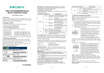
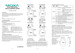
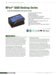
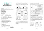
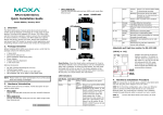
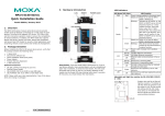
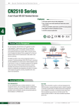
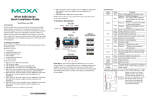
Rear panel of the NPort 5650 (Fiber Model) NPort 5600 Series Quick Installation Guide Third Edition, November 2010 Scrolls down through a list of items shown on the LCM panel’s second line. SEL Selects the option listed on the LCM panel’s second line. Detailed LCM Panel Operating instructions can be found on the CD-ROM in the NPort 5600 Series User’s Manual. ﹀ Rear panel of the NPort 5610 (DC Power) Link Indicator on the rear panel of the NPort 5650 fiber model—the rear panels of the NPort 5650 have a link indicator, as described in the following table. Front panel of the NPort 5650-T Series 1. Overview Welcome to the Moxa NPort 5600 Series. The NPort 5610-8/16 have 8 or 16 RS-232 ports, the NPort 5630-8/16 have 8 or 16 RS-422/485 ports, and the NPort 5650-8/16 have 8 or 16 RS-232/422/485 ports. 2. Package Checklist The NPort 5600 package should contain the following items: • • • 1 8-port or 16-port serial device server NPort Documentation & Software CD NPort 5600 Quick Installation Guide Reset Button—press the Reset button continuously for 5 sec to load factory defaults: Use a pointed object to press the reset button. Release the button after the Ready LED stops blinking. LED Indicators on the Front Panel—the front panels of the NPort 5600 have several LED indicators, as described in the following table. Name Ready Color Off Red Optional Accessories: • CBL-RJ45M9-150: 8-pin RJ45 to DB9 male cable, 150 cm • CBL-RJ45F9-150: 8-pin RJ45 to DB9 female cable, 150 cm • CBL-RJ45M25-150: 8-pin RJ45 to DB25 male cable, 150 cm • CBL-RJ45F25-150: 8-pin RJ45 to DB25 female cable, 150 cm Notify your sales representative if any of the above items is missing or damaged. 3. Hardware Introduction The NPort 5600 Series has includes the following models: NPort 5610-8, NPort 5610-16, NPort 5610-8-48V, NPort 5610-16-48V, NPort 5630-8, NPort 5630-16, NPort 5650-8, NPort 5650-8-T, NPort 5650-16, NPort 5650-16-T, NPort 5650-8-M-SC, NPort 5650-16-M-SC, NPort 5650-8-S-SC, and NPort 5650-16-S-SC. NOTE The wide temperature model does not support LCM display panels or push buttons. All of the LCM descriptions below apply only to standard temperature models. Green 1-16 Orange Green Off Function Power is off, or power error condition exists. Steady on: Power is on and the NPort is booting up. Blinking: Indicates an IP conflict, or DHCP or BOOTP server did not respond properly. Steady on: Power is on and the NPort is functioning normally. Blinking: The NPort has been located by NPort Administrator’s Location function. Serial port is receiving data. Serial port is transmitting data. No data is being transmitted or received through the serial port. LCM Display Panel—If the NPort is working properly, the LCM panel will display a green color. The red Ready LED will also light up, indicating that the NPort is receiving power. After the red Ready LED turns green, you will see a display similar to: N 1 P 9 5 2 6 . 1 1 0 6 8 1 . 6 1 2 3 7 8 . 2 5 4 Front panel of the NPort 5600 Series This is where • NP5610-16 is the NPort’s name • 38 is the NPort’s serial number • 192.168.127.254 is the NPort’s IP address Rear panel of the NPort 5610/5630/5650 (AC Power) LCM Panel Operation—There are four buttons on the NPort 5600’s front panel. These buttons are used to operate the server’s LCM panel. Going from left to right, the buttons are: The front and rear panels are shown below: Button MENU ︿ P/N: 1802056000211 –1– Action Activates the main menu, or returns to a lower level. Scrolls up through a list of items shown on the LCM panel’s second line. –2– LED Name LED Color Link Off Green Blinking LED Function Fiber disconnected. Fiber connected; data not transmitting. Fiber connected; data is transmitting. 4. Hardware Installation STEP 1: After removing the NPort 5600 from the box, the first thing you should do is attach the power adaptor. STEP 2: Connecting the Power. AC: Connect the NPort 5600’s 100-240 VAC power cord to the AC connector. The “Ready” LED will show a solid red color until the system is ready, at which time it will change to a green color. DC: Connect the NPort 5610-16/8-48V’s power cord to the DC connector, and then follow the steps given below: Loosen the screws on the V+ and V- terminals of the NPort 5610-8/16-48V’s terminal block. Connect the power cord’s 48 VDC or -48 VDC wire to the terminal block’s V+ terminal, and the power cord’s DC Power Ground wire to the terminal block’s V- terminal, and then tighten the terminal block screws. (Note: The NPort 5610-8/16-48V can still operate even if the 48V/-48V and DC Power Ground are reversed.) The “Ready” LED will show a solid red color until the system is ready, at which time it will change to a green color. Grounding the NPort 5610-8/16-48V: Grounding and wire routing help limit the effects of noise due to electromagnetic interference (EMI). Run the ground connection from the ground screw to the grounding surface prior to connecting devices. The Shielded Ground (sometimes called Protected Ground) contact is the second contact from the right of the 5-pin power terminal block connector located on the rear panel of the NPort 5610-8/16-48V. Connect the SG wire to the Earth ground. STEP 3: Connect the NPort 5600 to a network. Use a standard straight-through Ethernet cable to connect to a hub or switch. When setting up or testing the NPort 5600, you might find it convenient to connect directly to your computer’s Ethernet port. In this case, use a cross-over Ethernet cable. –3– STEP 4: Connect the NPort 5600’s serial port to a serial device. Serial Cables for the NPort 5630 (RS-422/4-wire RS-485) Placement Options: You can place the NPort 5600 on a desktop or other horizontal surface. 5. Software Installation Information To install NPort Administration Suite, insert the NPort Document & Software CD into your computer’s CD-ROM drive. Once the NPort Installation CD window opens, click on the INSTALL UTILITY button, and then follow the instructions on the screen. To view detailed information about NPort Administration Suite, click on the DOCUMENTS button, and then select “NPort 5600 Series User’s Manual” to open the PDF version of this user’s guide. Serial Cables for the NPort 5610/5650 (RS-232) 6. Pin Assignments and Cable Wiring Serial Port Pinouts for the NPort 5610 Pin 1 2 3 4 5 6 7 8 RS-232 DSR (in) RTS(out) GND TxD(out) RxD(in) DCD(in) CTS(in) DTR(out) Serial Port Pinouts for theNPort 5630 Pin 1 2 3 4 5 6 7 8 RS-422/RS-485-4W – – TxD+ TxDRxDRxD+ GND – RS-485-2W – – – – DataData+ GND – Serial Cables for the NPort 5650 (RS-422/4-wire RS-485) Serial Port Pinouts for the NPort 5650 Pin 1 2 3 4 5 6 7 8 RS-232 DTR RTS GND TxD RxD DCD CTS DTR RS-422/RS-485-4W – TxD+ GND TxDRxD+ RxD– – RS-485-2W – – GND – Data+ Data– – 7. Specifications Ethernet Interface Speed 10/100 Mbps, RJ45 Protection Built-in 1.5 KV magnetic isolation Optical Fiber Interface (100BaseFX) 5650-8/16-M-SC 5650-8/16-S-SC Wavelength 1300 nm 1310 nm Transmitter power Max -10 dBm 0 dBm Transmitter power Min -20 dBm -5 dBm Receiver Sensitivity Max -6 dBm -3 dBm Receiver Sensitivity Min -32 dBm -34 dBm Link Budget 12dB 29 dB Typical Distance 5 km 40 km Power Requirements 100 to 240 VAC, 47 to 63 Hz, ±48 VDC (20 Power Input to 72 VDC, -20 to -72 VDC) Power Consumption NPort 5610-8/16: 141 mA for 100V, 93 mA for 240V NPort 5610-8/16-48V: 135 mA (at 48V max.) NPort 5630-8/16: 152 mA for 100V, 98 mA for 240V NPort 5650-8/16: 158 mA @ 100 VAC, 102 mA @ 240 VAC NPort 5650-8/16-S-SC: 164 mA @ 100 VAC, 110 mA @ 240 VAC NPort 5650-8/16-M-SC: 174 mA @ 100 VAC, 113 mA @ 240 VAC Other Operating Temp. Standard Models: 0 to 55°C (32 to 131°F) Wide Temp. Models: -40 to 75°C (-40 to 167°F) Operating Humidity 5 to 95% RH Dimensions 190 × 45 × 478 mm (including ears) 190 × 45 × 440 mm (without ears) Serial Line Protection 15 KV ESD for all signals Power Line Protection Level 3 Burst (EFT), EN61000-4-4 Level 3 Surge, EN61000-4-5 Regulatory Approvals FCC Class A, CE Class A, UL 60950-1, EN60950-1 Serial Cables for the NPort 5650(2-wire RS-485) Serial Cables for the NPort 5630 (2-wire RS-485) www.moxa.com/support The Americas: Europe: Asia-Pacific: China: +1-714-528-6777 (toll-free: 1-888-669-2872) +49-89-3 70 03 99-0 +886-2-8919-1230 +86-21-5258-9955 (toll-free: 800-820-5036) 2010 Moxa Inc., All Rights Reserved –4– –5– –6–