1
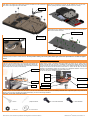
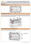
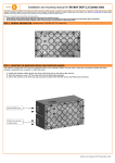
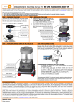
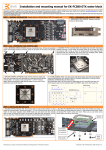
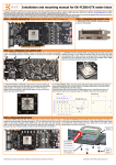
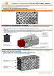
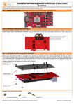
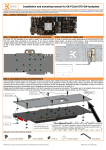
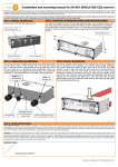
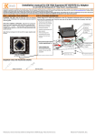
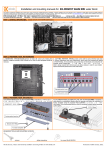
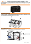
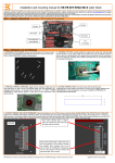
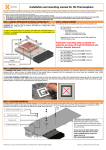
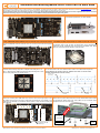
Installation and mounting manual for EK-FC5x0 GW GTX water block
This product is intended for installation only by expert users. Please consult with a qualified technician for installation. Improper installation may result in damage to your equipment. EK Water Blocks assumes no liability
whatsoever, expressed or implied, for the use of these products, nor their installation. The following instructions are subject to change without notice. Please visit our web site at www.ekwaterblocks.com for updates.
Before installation of this product please read important notice, disclosure and warranty conditions printed on the back of the box or our home page.
The barb hose fittings require only a small amount of force to screw them in; otherwise the high flow fittings might break. These fittings do not need to be tightened with much force because the
liquid seal is made using o-rings. The use of an algaecide and corrosion inhibitors is always recommended for any liquid cooling system.
STEP 1: GENERAL INFORMATION. Sample picture of GW/Palit GeForce 570/580 GTX graphics card
STEP 2: PREPARING YOUR GRAPHIC CARD.
1. REMOVING STOCK COOLER: Remove encircled screws
on the bracket (required only on certain models):
STEP 2 cont.: PREPARING YOUR GRAPHIC CARD
1 cont.. REMOVING STOCK COOLER. Remove all encircled screws. All heat sink assembly 2. CLEANING THE PCB. Carefully detach the original heat sink after removing all
screws and backplate should be removed. There are 21 screws on the back of the graphic
card.
3. APPLYING THERMAL COMPOUND. Apply thermal compound: lightly
coat both GPUs and bridge chip with for example Arctic Cooling MX-2 ™ or
MX-4 ™ thermal grease. EKWB recommends to apply thermal grease in cross
form for best performance (see sample picture).
fasteners securing it to the board and bracket. Wipe off the remains (by using
non–abrasive cloth or Q-tip, as shown on sample photo) of the original thermal
compound until the components and circuit board are completely clean. EKWB
does not recommend using any liquids for removing paste.
4. CUTTING THERMAL PADS. Your block comes with thermal pads, some of which are already
pre-cut. Others have to be cut to smaller chunks in order to cover all the VRM components
(PLEASE REMOVE FOIL ON BOTH SIDES OF THERMAL PADS PRIOR TO INSTALLATION.
WARNING: DIMENSION BELLOW ARE SCALED).
Thickness 1mm
(for memory)
1
1
1
1
1
1
1
1
1
1
1
1
1
2
Thickness 1mm
(for VRM)
Thickness 1.5mm
(for VRM)
STEP 3: INSTALLING WATER BLOCK
1. PLACING THERMAL PADS ON PCB. Place thermal pads on chips so that numbers on chips
match size of thermal pads. EKWB made sure users have more than enough pads to cover
all surfaces that need to be covered to make block fully functional). It is advised to use
small drops of electrically non-conductive thermal grease on chips to make thermal pads
more adhesive.
2. PLACING GPU REINFORCE PLATE ON PCB. Place metal reinforce and washer on
PCB as shown on picture below and screw it in with enclosed M3x4 screws. Please
use encased PVC washers under each screw. Make sure you use fasten screws
equally and do not use too much force.
Washer
1
1
1
1
1
1
1
1
1
1
1
1
1
1
2
1
1
For GeForce GTX 580
models only!
All disclosures, notices and warranty conditions are being written on the back of the box.
Orientation
of reinforcer
is important!
M3x4
screw
PVC washer
th
Released on 25 of March, 2011. Revision 1.0
3. PLACING STANDOFFS ON BLOCK. Brass standoffs are obligatory in order to attach this
water block to the printed circuit board of the graphics card. Please use the encased key to
screw them to the copper base of the water block
4. PLACING BLOCK TO GRAPHIC CARD. During this process please make sure you
align holes on PCB with holes on block. Also pay attention not to use too much
force by pressing block down to PCB. Chip dies are prone to cracking.
Standoff key
5. ATTACHING BLOCK TO GRAPHIC CARD. By using Philips screwdriver screw in
enclosed M3x4 screws. EKWB recommends start screwing the screws around the
GPU core and continue outwards.
Tightening the standoffs:
Use 12 screws M3x4
Brass M4-M3
3.3mm standoff
Tightening the standoff:
Use 12 enclosed PVC
washers.
STEP 4: CHECKING FOR CONTACTS
Temporarily remove the water block to check for uniform surface contact between the block and the components. Note the pattern of contact on a piece of paper. Then repeat
substeps in previous section to reattach the block. In case you fail to obtain good contact, please check again your thermal pad thickness or contact our support
service.
STEP 5: SECURING I/O BRACKET
STEP 6: FITTING POSITIONING
Use one M3x6 screw, one PVC washer and one M3 nut to secure the I/O
(also known as PCI) bracket firmly to the circuit board. This will allow the
computer chassis to carry the weight of the waterblock thus reducing the
tension on the PCI-express slot. Tighten the screw with Philips screwdriver
while holding the M3 nut with your thumbs firmly.
Please use spacer only on copper base if you use fitting with G1/4 thread longer than 5mm (see
sample picture). Screw in the fittings and plugs (please use spacers only on copper base for
fittings). Use 6mm Allen key to screw in and tighten new EK-Plug G1/4. Attach the liquid cooling
tubes and connect the water-block(s) into the cooling circuit. EKWB recommends using high flow
fittings with the EK-FC 5x0 GW GTX series water blocks. To ensure that the tubes are securely
attached to the barb/fittings, please use hose clamps or an appropriate substitute. The use of an
algaecide is always recommended for any liquid cooling system.
You can use any hole as an inlet/outlet port.
M3x6 screw
Fitting
G1/4
Spacer
6mm Allen key
PVC washer
Gasket/O-ring
M3 nut
Plug with o-ring
Plug with o-ring
STEP 6: INSERTING CARD IN YOUR PC CASE
Carefully lift your card with installed block and insert it in your PC case. Please bear in mind that your card suddenly withstands extra weight thus again be very careful not to
bend it or cause any other unneeded moves that might damage your card or block during installation.
REQUIRED TOOLS AND MOUNTING SCREWS:
scissors
1 × M3 nut
philips screwdriver
16 × screws M3x4 DIN7985
1 × M3x6 DIN7985
16 × PVC washers
All disclosures, notices and warranty conditions are being written on the back of the box.
th
Released on 25 of March, 2011. Revision 1.0