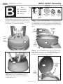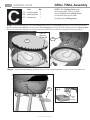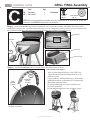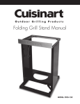
1
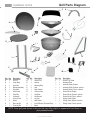
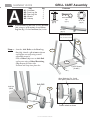
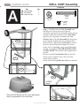
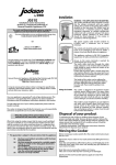
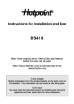
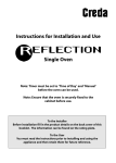
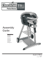
Assembly Guide Model Numbers: 12601559 12601578 12601663 12601664 12601665 12601688 12601514 12601514-C1 ELECTRIC (English) 42804641 • 09/14/11 A, B, C, Assembly: 2 ASSEMBLY GUIDE CAUTION: For your safety, before operating, Read Product Guide & Outdoor Cooking Guide provided with this grill. *SAFETY First…..Grill components may have sharp edges. Be careful when handling grill parts during assembly. We suggest that you wear a sturdy pair of leather gloves while handling the grill parts. BEFORE You begin assembly of your grill…. 1. Carefully remove all components from the carton. 2. Familiarize yourself with the components and hardware used for assembly. 3. Please note that hardware used for assembly may not be shown actual size.. 4. After removing components from the carton, split the carton open and use it as a soft, scratch-free work pad to assemble your grill. BEFORE You Grill…. 1. Read Product Guide & Outdoor Cooking Guide 2. Position Grill Safely away from walls & structures. 3. Pre– Heat Grill—15 minutes on 5 ,High to season grill. NOTE…. Installer: Leave instructions with the grill. Consumer: Retain instructions for reference. Grill must be installed in accordance with local codes….. Designed for outdoor use only… Read all instructions before operating… TOOLS REQUIRED FOR ASSEMBLY (Not Supplied) Phillips Head Screwdriver Visit www.charbroil.com/live Small Adjustable Wrench 3 ASSEMBLY GUIDE Grill Parts Diagram F H D w A Q O V G X R B I B E L K C N P J S U U T Key Qty A 1 B 1 C 1 D 1 E 1 F 1 G 1 H 1 I 1 J 2 K 1 L 1 Description Grill Lid Lower Body Controller Element Assembly Wire Shelf Wind Shield Towel Bar Lid Handle Control Panel Wheel Rear Leg Set Front Leg Set Key Qty M 1 N 2 O 1 P 2 Q 1 R 1 S 1 T 1 U 2 V 1 W 1 X 1 M Description Grease Tray Hubcap Warming Rack Axle Heat Indicator Cooking Grate Cart Base Cart Bracket Leg Cap Heat Shield Inner Reflector (Porcelain Bowl) Bezel Key Qty Y 1 — 1 — 1 — 1 — 1 — 1 — 1 — 1 — 1 — 1 — 1 Y Description Grease Tray Guide Hardware Pack Assembly Guide, English Assembly Guide, Spanish, optional Assembly Guide, French, optional Product Guide, English Product Guide, Spanish, optional Product Guide, French, optional Grilling Guide, English Grilling Guide, Spanish, web only Grilling Guide, French, optional NOTE: Some grill parts shown in the parts list may differ slightly in appearance from those on your particular model. Visit www.charbroil.com/live 4 ASSEMBLY GUIDE GRILL CART Assembly Part A1– Cart Base A2– Front Leg Set A3– Rear Leg Set A4– Wheels A5– Hubcap Qty 1 1 1 2 2 Fasteners . 1/4x20-1/2" screw (qty 4) Wheel Retaining Clip (qty 2) 3/8-16 Nut (qty 2) Step 1– Attach Front Leg Set (A2) to the Cart Base (A1) using 2 1/4-20 screws. Attach Rear Leg Set (A3) to the Cart Base (A1) in the Axle Bolt (qty 2) After cart assembly, if your cart does not sit level, use these screws to A3 Step 2 – Attach 2 Axle Bolts to the Rear Leg A2 Set (A3), thread a 3/8-16 nut as shown and tighten securely using a small adjustable wrench. Slide a Wheel (A4) over an Axle Bolt and secure using a Wheel Retaining Clip. Repeat for other side. Position and Snap into place the A1 1/4-20 Screws (4 each) Wheel Retaining Clip - Install after placing wheel on the axle. Axle Bolt Axle Nut 3/8-16 A5 Position wheel as shown A4 Visit www.charbroil.com/live 5 ASSEMBLY GUIDE GRILL CART Assembly Fasteners Part A6– Cart Bracket A7– Wire Shelf A8– Leg End Cap Qty 1 1 2 . 1/4x20-2" screw (qty 4) 1/4-20 Nut (qty 4) #10x3/8" screw (qty 2) Step 3 - Carefully turn the Cart Assembly over and allow it to rest on the tops of the leg assemblies. Spread the leg assemblies apart just far enough to allow the insertion of the Wire Shelf (A7) into the 4 leg holes. Assemble the Cart Bracket (A6) to the Cart Assembly by inserting 4 each 1/4-20x2" screws int0 into corresponding holes as shown. Allow the Cart Bracket to rest on the floor, this will help with alignment. Secure with 4 each, 1/4-20 nuts using a small adjustable wrench, not supplied. FINGER TIGHTEN ONLY AT THIS POINT. The bracket will be tightened in step B2. Be sure to install Cart Bracket (A6) on the side shown. Once complete -leave the cart in the upside down position. Lastly, insert the Leg End Caps (A8) into the front A7 A6 A7 A6 1/4-20x2" screws #10x3/8" screws Place the Grill Bottom on the carton pad upside down in preparation for the next step. Visit www.charbroil.com/live A8 6 ASSEMBLY GUIDE GRILL BODY Assembly Fasteners Part Qty. B1– Lower Body 1 B2– Wind Shield 1 B3– Grill Lid 1 ASSEMBLY Step 1 - Attach the Lower Body Assembly (B1) to the Cart Assembly by aligning the studs on the bottom of the grill with the corresponding holes in the tops of the leg assemblies. Secure with 7 each 10-24 nuts. A Nut Driver (not supplied) will work nicely for this step. 10-24x3/8" screw (qty 3) 1/4-20 Nut 10-24 Nut (qty 2) (qty 10) Step 3 - Attach the Wind Shield (B2) to the Lower Body (B1) by aligning the holes in the panels with the corresponding holes in the Lower Body. Secure with 3 10-24 nuts, 3 10-24x3/8" Screws, and 3 fiber washers. The Wind Shield will rest inside the Lower Body. 10-24 Nuts (3 each) Studs located on Lower Body Assembly 1/4-20x3/4" Fiber Washer (qty 5) Hinge screw (qty 2) 10-24x3/8" Screws (3 each) B2 B1 B1 Fiber Washer (3 each) Cart Bracket Step 4 - Attach the Grill Lid (B3) by aligning the hinge holes in the lid to the matching holes in the Wind Shield (B2). Insert 2 Hinge Screws into the holes and secure with 2 1/4-20 nuts and two Fiber washers from the inside of the grill. B1 1/4-20x3/4" B3 Step 2 - With the legs assembled to the Lower Body, tighten the 4 screws holding the Cart Bracket in place. Once complete, turn the grill over to the upright position. Hinge Screws (2 each) Fiber Washer (2 each) Visit www.charbroil.com/live 1/4-20 Nuts (2 each) 7 ASSEMBLY GUIDE GRILL FINAL Assembly Part NOTE: The Cooking Grate may have sharp edges. Be very careful when handling the Cooking Grate. You should wear gloves when handling the Cooking Grate. Qty. C1 – Cooking Grate C2 – Warming Rack C3 – Grease tray 1 1 1 Step 1 - With the Grill Lid open, place the Cooking Grate (C1)into the Lower Body, allowing it to rest on the three brackets spaced around the Lower Body. Be sure the slots in the Cooking Grate are facing the front of thegrill. Place the Warming Rack (C2) into position by first hooking the center pins into the wind shield, then rotate the warming rack down into position. Slots to the front of the grill. C2 C1 Step 2 - Install the Grease Tray (C3) by sliding the tray onto the Grease Tray Rails from the rear of the grill. Note: The Grease Tray Rails C3 Fig. A Grease Tray Rail Stops Visit www.charbroil.com/live GRILL FINAL Assembly 8 ASSEMBLY GUIDE Part Qty. C4 – Controller C5 – Lid Handle 1 1 Fasteners 10-24x3/8" screw (qty 2) Fiber Washer (qty 2) NOTE: Be sure to press the controller into the receptacle as far as it will go. Route the controller cord BEHIND the towel bar as shown. Step 3 - Install the Controller (C4) into the receptacle. Be sure to route the controller cord behind the towel bar when installing the controller. The control knob should be facing up as you engage the tip of the controller into the receptacle. Push the controller in all the way until you hear a click, this will ensure your controller is installed properly. Receptacle Towel Bar Controller C4 Controller Tip Step 4 - Install the Lid Handle with 2 10-24x3/8" screws and 2 fiber washers as shown. Ground Fault Interrupter Since 1971 the National Electric Code (NEC) has required Ground Fault Interrupter devices on all outdoor circuits. If your residence was built before 1971, check with a qualified electrician to determine if a Ground Fault Interrupter protector exists. Do not use this appliance if the circuit does not have GFI protection. Do not plug this appliance into an indoor circuit. C5 Fiber Washer (2 each) 10-24x3/8" Screws (2 each) Congratulations! You have successfully completed the assembly of your grill. Visit www.charbroil.com/live