1
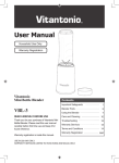
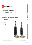
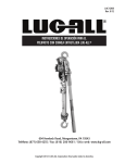
OPERATING INSTRUCTIONS
INSTRUCCIONES DE OPERACIÓN
WARRANTY
The Koblenz Upright vacuum cleaner is warranted to be free from all defects in materials and workmanship in a
period of one year. The metal chassis is warranted for a total of 5 years. The switch, fan and metal yoke are
warranted for a total of 2 years.
The warranty does not cover parts that wear under normal use such as belts, brush rolls, light bulbs, cloth and
paper bags and bumpers.
This warranty shall not apply to damage or malfunction caused by negligence, abuse or product which has been
altered or repaired by an unauthorized person or service center. To validate this warranty, you only need to show
this contract along with proof of purchase in anyone of the service centers (see enclosed list of authorized service
centers or call 1-800-849-4711 for instructions).
Koblenz will either repair or replace, at its election, all defective machines during the warranty period. The foregoing
obligations are in lieu of all other obligations and liabilities including negligence and state Koblenz's entire and
exclusive liability and purchaser's exclusive remedy. Koblenz will in no event be liable for any direct, indirect,
special, incidental or consequential damages or losses whatsoever and Koblenz's liability under no circumstances
will exceed the contract price for the goods or parts for which liability is claimed.
THORNE ELECTRIC Co.
P.O. BOX 18363
SAN ANTONIO, TX.
78218-0363 U.S.A.
SERVCE CENTER AND
PARTS INFORMATION
CALL TOLL FREE:
TEL: 1 (888) 647 1433
CANADIAN CALL
COLLECT:
TEL: (210) 590-1226
FAX: (210) 590 1258
•COMMERCIAL AND HOSUEHOLD
UPRIGHT VACUUM CLEANERS
•BARREDORAS VERTICALES
CONGRATULATIONS!
You have just acquired a Koblenz Electric Vacuum
Cleaner, please read this manual carefully before
connecting your Vacuum Cleaner.
Keep this manual at hand for further references.
¡FELICIDADES!
Made in Mexico
GARANTíA
La barredora Koblenz está garantizada contra defectos en materiales y mano de obra en un periodo de un año.
El chasis metálico por un total de 5 años. El switch, la turbina y yugo metálico por un total de 2 años.
La garantía no cubre las partes que por uso normal sufran desgaste, como son bolsas, bandas, cepillos,
focos y molduras. La garantía no aplica en el caso que el producto haya sido utilizado con negligencia, abuso
o si el producto ha sido alterado o reparado por una persona o centro de servicio no autorizado. Para hacer
efectiva esta garantía, solo se requiere la presentación del producto y la póliza correspondiente debidamente
sellada por el establecimiento que lo vendió, en cualquiera de los centros de servicio autorizados (vea lista de
Centros de ServicioAutorizados o llame al 1-800-849-4711 para mayores informes). Koblenz podrá reparar o
remplazar la máquina durante el periodo de garantía. Las obligaciones anteriores son en vez de cualquier otra
obligación incluyendo negligencia y expresan la completa y única obligación de Koblenz así como el único
remedio del comprador. Koblenz bajo ninguna circunstancia será responsable por daños directos, indirectos,
incidentales o consecuenciales, y la responsabilidad de Koblenz no excederá bajo ninguna circunstancia el valor
del producto.
Fabricado por Koblenz Eléctrica, S.A. de C.V.
Producto:
Av. Ciencia No. 28, Cuautitlán Izcalli
Modelo:
Edo. de México, C.P. 54730
No. de Serie:
IMPRESO EN MÉXICO
Nombre del distribuidor:
Calle y Número:
CENTROS DE SERVICIO
Colonia o Poblado:
Ciudad / Código Postal:
México, D.F. 5203-5525 / 5250-8233
Fecha de entrega:
Guadalajara 01800711-8046/01800711-8047
Sello y Firma:
Monterrey
01800711-8114/01800712-7714
Para mayores informes sobre un taller autorizado cerca
de su localidad llame sin costo al 01-800 849-4711
SERVICIO Y REFACCIONES EN TODA LA REPÚBLICA
19-0335-5 F
11-03
HECHO EN MÉXICO
Acaba de adquirir una Barredora Koblenz,
por favor lea este manual antes de conectar
su barredora.
Conserve este manual para futuras referencias.
Características
Eléctricas
Electrical Rating
Modelos
Models
U-110
U-110-Z
U-110-DC
U-180-DC
U-240
U-240-DC
U-310
U-310-Z
U-310-DC
U-350
7,0 A
7,0 A
7,0 A
7,0 A
7,5 A
7,5 A
7,5 A
7,5 A
7,5 A
7,5 A
60Hz 120 V~
60Hz 120 V~
60Hz 120 V~
60Hz 120 V~
60Hz 120 V~
60Hz 120 V~
60Hz 120 V~
60Hz 120 V~
60Hz 120 V~
60Hz 120 V~
Koblenz Eléctrica, S.A. de C.V.
Av. Ciencia No. 28 Cuautitlán Izcalli
Estado de México, C.P. 54730
Tel: 5864-03-00
Modelos
Models
U-350-Z
U-510
U-510-Z
U-510-DC
U-530
U-530-Z
U-610
U-610-Z
U-610-DC
7,5 A
9,0 A
9,0 A
9,0 A
9,0 A
9,0 A
9,0 A
9,0 A
9,0 A
Características
Eléctricas
Electrical Rating
60Hz 120 V~
60Hz 120 V~
60Hz 120 V~
60Hz 120 V~
60Hz 120 V~
60Hz 120 V~
60Hz 120 V~
60Hz 120 V~
60Hz 120 V~
60Hz 120 V~
U-240, U-240-DC MODELS, ARE FOR DOMESTIC USE ONLY, AND HAVE A POLARIZED CONNECTION PLUG (SEE
PAGE 4) U-110, U-110-Z, U-110-DC, U-180-DC, U-310, U-310-Z, U-310-DC, U-350, U-350-Z, U-510,
U-510-Z, U-510-DC, U-530, U-530-Z, U-610, U-610-Z, U-610-DC ARE MODELS DESIGNED FOR BOTH DOMESTIC
AND COMMERCIAL USES AND HAVE A GROUNDED PLUG.
COMO REEMPLAZAR LA BANDA DEL RODILLO
Apague y desconecte la barredora antes de reemplazar la banda. La banda se
calienta durante el uso normal. Evite tocarla.
IMPORTANT SAFETY INSTRUCTIONS
• WHEN USING AN ELECTRICAL UPRIGHT VACUUM CLEANER, BASIC PRECAUTIONS SHOULD BE FOLLOWED,
INCLUDING THE FOLLOWING.
• READ ALL INSTRUCTIONS BEFORE USING VACUUM CLEANER.
SAVE THESE INSTRUCTIONS FOR FURTHER REFERENCE
WARNING
To reduce risk of fire, electric shock, or injury:
• Do not use outdoors or on wet surfaces.
• Do not leave vacuum cleaner unattended when plugged in. Turn off switch and unplug the electrical cord when not in use and before
servicing.
• Do not allowed to be use as a toy. Close attention is necessary when use by or near children.
• Use only as described in this manual. Use only manufacturer's recommended attachments.
• Do not use with damaged cord or plug. If vacuum cleaner is not working as it should, has been dropped, damaged, left outdoors,
or dropped into water, return it to a service center before using.
• Do not pull or carry by cord, use cord as a handle, close a door on cord, or pull cord around sharp edges or corners, do not run
vacuum over cord. Keep away from heated surfaces.
• Do not use extension cords or outlets with inadequate current carrying capacity.
• Turn off all controls before unplugging.
• Do not handle plug or vacuum cleaner with wet hands.
• Do not put any object into openings. Do not use with any opening blocked, keep free of dust, lint, hair and anything that may reduce
airflow.
• This vacuum cleaner creates suction and contains a revolving brush roll. Keep hair, loose clothing, fingers and all parts of body away
from openings and moving parts.
• Do not pick up anything that is burning or smoking, such as cigarettes, matches or hot ashes.
• Do not use without dust bag in place.
• Use extra care when cleaning on stairs.
• Do not use to pick up flammable or combustible liquids such as gasoline, or use in areas where they may be present.
• Store your cleaner indoors in a cool, dry area.
• Do not unplug by pulling on cord. To unplug, grasp the plug, NOT THE CORD.
• If the feeding wire (flex) gets damaged, it must be replaced by the manufacturer, by your service agent or by other qualified personnel,
in order to avoid any risks.
The following upright models have grounded line cords and need to be connected to a properly grounded outlet only. See grounding
instructions for the models listed below.
GROUNDED MODELS:
* U-110
* U-110-Z * U-110-DC U-180-DC * U-310
* U-310-Z
* U-310-DC U-350
U-350-Z
* U-510
* U-510-Z
* U-510-DC
U-530
U-530-Z * U-610
* U-610-Z * U-610-DC
*For your convenience, this upright model includes a pigtail plug and a separate line cord (SJT 16/3) to facilitate handling. To use, just
connect the plug into line cord then plug the line cord into an outlet. Please note that if you wish to replace the line cord it must always
be caliber SJT 16/3.
GROUNDING INSTRUCTIONS. This appliance must be grounded. If it should malfunction or breakdown, grounding provides a path
of least resistance for electric current to reduce the risk of shock. This appliance is equipped with a cord having an equipment-grounding
conductor and grounding plug. The plug must be inserted into an appropriate outlet that is properly installed and grounded in accordance
with all local codes and ordinances.
WARNING. Improper connection of the equipment-grounding conductor can result in a risk of electric shock. If you are in doubt as to
whether the outlet is properly grounded check with a qualified electrician or service person. Do not modify the plug provided with the
appliance - if it does not fit the outlet, have a proper outlet installed by a qualified electrician.
This appliance is for use on a nominal 120 volt circuit, and has a grounded plug that looks like the plug illustrated in sketch A. A temporary
adaptor that looks like the adaptor illustrated in sketches B and C may be used to connect this plug to a 2- pole receptacle as shown
in sketch B if a properly grounded outlet is not available. The temporary adaptor should be used only until a properly grounded outlet
(sketch A) can be installed by a qualified electrician. The green color rigid wire, lug, or the like extending from the adaptor must be
connected to a permanent ground such as a properly grounded outlet box cover.
NOTE: In Canada, the use of temporary adaptor is not permitted by the Canadian Electric Code.
Warning: The power cord on this product contains lead, a chemical known to the State of California to cause birth defects or other
GROUNDING
reproductive harm. WASH HANDS AFTER HANDLING.
PRECAUCIÓN: La instalación inapropiada del rodillo o de la banda, puede dañar
la barredora.
VARILLA
RETEN
CUBIERTA
DEL
VENTILADOR
1. Empuje el pedal de posiciones para liberar el tubo manija, bájelo y voltee la
barredora boca abajo (fig. 6)
2. Quite la varilla retén empujándola hacia abajo por el extremo derecho hasta
que se desenganche, libere el otro extremo y quite la tapa rodillo.
TAPA
RODILLO
FIG. 6
CEPILLO
GIRATORIO
PRECAUCIÓN: Mientras empuja un extremo de la varilla retén, sostenga y
presione el otro extremo para evitar que salte.
3. Quite la banda de la tuerca del motor, levante el rodillo, quite la banda usada
y sustitúyala por una nueva.
CUBIERTA
DEL
MOTOR
TUERCA
DEL
VENTILADOR
4. Ponga el rodillo asegurándose que ambos extremos del soporte balero estén
hacia arriba. Las cerdas del rodillo formaran una "V" frente a usted.
5. Tuerza la banda hacia la derecha y acomódela alrededor de la tuerca del motor.
La parte alta de la banda debe localizarse del lado derecho y la parte baja del
izquierdo (fig 8). Observe los gravados en el chasis y asegúrese que la banda
queda como se indica.
6. Cuando cambie la banda es conveniente limpiar el rodillo y la turbina; el rodillo
generalmente acumula hilos en los portabaleros. Quite los portabaleros,
jalándolos hacia fuera, y limpie los baleros; para ensamblarlos colóquelos en el
mismo lugar presionando hacia adentro en ambos lados hasta su posición
original. Limpie la turbina quitándole el exceso de suciedad y reinstale los
componentes: tapa, ventilador y banda, como se describe.
BANDA
FIG. 7
POSICION ALTA
DE LA BANDA
POSICION BAJA
DE LA BANDA
FIG. 8
COMO REEMPLAZAR EL FOCO (MODELOS U-240, U-530, U-530-Z)
Desconecte la barredora antes de reemplazar el foco.
VARILLA
CUBIERTA
DEL
RETEN
1. Quite la bolsa y desconecte el tubo manija del socket.
VENTILADOR
2. Quite el tornillo de la perilla de ajuste de altura y remueva
la perilla.
3. Volteé la barredora boca abajo, con la ayuda de unas pinzas
desenganche del chasis los resortes que sostienen la cubierta
de la barredora (fig.6) jalándolos para liberar su gancho.
4. Sostenga la barredora por la cubierta, voltéela hacia arriba y
quite la cubierta.
5. Retire el foco jalándolo hacia arriba moviéndolo ligeramente
hacia la izquierda y derecha, el foco no sale dando vueltas.
CEPILLO
TAPA
6. Para poner el foco nuevo alineé la base con el socket y empújelo
GIRATORIO
RODILLO
adentro (fig 9).
7. Ponga la cubierta en su lugar, volteé la barredora boca abajo y
FIG. 6
enganche los resortes al chasis.
8. Reemplace la perilla de ajuste de altura y apriétela con su tornillo.
Unplug upright before replacing fan.
FOCO
FIG. 9
COMO REEMPLAZAR LA TURBINA
Desconecte la berradora antes de reemplazar la turbina.
1. Sostenga la turbina con la mano para evitar que gire, utilice un guante.
2. Con una llave de 3/4 gire la tuerca polea, en sentido contrario a las
manecillas del reloj para liberarla.
3. Quite la turbina y reemplacela por una nueva, asegurándose que el
espaciador y las rondanas de fibra estén en la posición adecuada.
(ver dibujo)
tuerca polea
rondana de fibra
turbina
rondana de fibra
espaciador
mango del motor
OUTLET
METAL
SCREW
2
GROUNDED
OUTLET BOX
GROUNDING
PIN
ADAPTOR
(A)
(B)
(C)
TAB FOR
GROUNDING SCREW
11
COMO UTILIZARSE
GENERAL DIAGRAM
Encienda presionando el pedal retén y jalando la manija hacia atrás,
para barrer por debajo presione el pedal otra vez y baje la manija hasta el piso
si es necesario (fig 4).
DIAGRAMA GENERAL
Dust cup models: Page 4 and 5
Modelos con copa de polvo: Pág. 5 y 9
APAGADO
Barra con movimientos lentos hacia delante y hacia atrás cubriendo áreas pequeñas.
EN OPERACIÓN
Para apagar levante la manija hasta la posición vertical.
El tiempo necesario para barrer una alfombra depende del tipo de alfombra y la
cantidad de polvo.
Cuando almacene su barredora, enrolle el cable procurando no torcerlo y cuélguelo
en el gancho superior del tubo manija, si así está equipado, o enróllelo en ambos
ganchos del tubo manija y asegúrelo con el clip que va integrado a la clavija.
ASPIRADO POR DEBAJO
FIG. 4
15
13
13A
AJUSTE DE ALTURA
La barredora tiene un control de ajuste deslizable que sube o baja el frente, lo que
acerca o separa el rodillo encerdado de la alfombra.
En alfombra de pelo corto la perilla de ajuste debe colocarse a la izquierda y de
pelo largo a la derecha.
PARTS LIST
AJUSTE DE ALTURA
Para mover la perilla incline el tubo manija hacia atrás hasta levantar el frente de
la máquina y en esa posición mueva la perilla.
FIG. 5
MANTENIMIENTO
COMO CAMBIAR LA BOLSA DE PAPEL (MODELOS “Z”)
Desconecte la barredora antes de cambiar la bolsa.
Cambie la bolsa de papel frecuentemente, algunas partículas finas pueden restringir el paso del aire y disminuir el poder de
succión aun antes de que la bolsa parezca estar llena. Por esta razón, la bolsa necesita ser cambiada
mas frecuentemente al aspirar polvos de alfombras, polvos de pastas o substancias finas similares.
(bolsa No. Parte 45-0315-7).
1. Desenganche el resorte de la bolsa, gire la perilla para liberar el cople y retire la bolsa completa de la barredora.
2. Abra el cierre de la bolsa de tela deslice el resorte retén hacia abajo para liberar el tubo de la bolsa de papel retire
el tubo y saque la bolsa de papel.
3. Coloque la bolsa de papel nueva cuidando que la impresión del cierre en la bolsa quede hacia el cierre de la bolsa
de tela, inserte el tubo de la bolsa de papel en el tubo conectivo y suba el resorte retén sobre el tubo de papel.
4. Limpie la salida de aire de la barredora cada vez que cambie la bolsa.
5. Instale la bolsa en su posición de funcionamiento con la impresión hacia el tubo manija.
COMO LIMPIAR LA BOLSA PERMANENTE (TODOS EXCEPTO LOS MODELOS “Z”)
Desconecte la barredora antes de limpiar la bolsa.
1. Desenganche el resorte de la bolsa, gire la perilla para liberar el cople y retire la bolsa completa de la barredora.
2. Quite el clip de la bolsa deslizándolo lateralmente, abra la parte superior de la bolsa introdúzcala en una bolsa de basura y
vacíela sacudiéndola.
3. Coloque el clip asegurándose que la bolsa quede bien cerrada, acomode los pliegues.
4. Limpie la salida de aire de la barredora cada vez que vacíe la bolsa.
5. Instale la bolsa en su posición de funcionamiento, con la impresión hacia el tubo manija.
RODILLO
10
14
1.
2.
3.
4.
5.
6.
7.
8.
9.
10.
11.
12.
13.
13a.
14.
15.
LISTA DE PARTES
Cord hook
Upper handle tube
Nut & bolt
Lower handle tube
Nut & bolt
Height adjustment
Headlight (models U-180-DC,U-240, U-530, U-530-Z)
Air outlet
Bag support
Handle release pedal
Bag
Spring bag hook
50 ft line cord
35 ft line cord for the U-110 series
3 wire grounded plug
Pigtail plug
1.
2.
3.
4.
5.
6.
7.
8.
9.
10.
11.
12.
13.
13a.
14.
15.
Gancho del cordón
Tubo superior de la manija
Tornillo y tuerca
Tubo inferior de la manija
Tornillo y tuerca
Ajuste de altura
Luz (modelos U-180-DC,U-240, U-530, U-530-Z)
Salida de aire
Soporte de la bolsa
Pedal retén manija
Bolsa
Sostén de la bolsa
Cable de 15 m.
Cable de 10 m. en modelos serie U-110
Clavija aterrizada
Conexión a cable de línea
MODEL
MODELO
A
BAG TYPE / TIPO DE BOLSA
LIGHT / LUZ
U-110
U-110-Z
U-110-DC
U-180-DC
U-240
U-240-DC
U-310
U-310-Z
U-310-DC
U-350
U-350-Z
U-510
U-510-Z
U-510-DC
U-530
U-530-Z
U-610
U-610-Z
U-610-DC
7,0
7,0
7,0
7,0
7,5
7,5
7,5
7,5
7,5
7,5
7,5
9,0
9,0
9,0
9,0
9,0
9,0
9,0
9,0
Permanent / Permanente
Disposable / Desechable
Dust Cup / Copa de Polvo
Dust Cup / Copa de Polvo
Disposable / Desechable
Dust Cup / Copa de Polvo
Permanent / Permanente
Disposable / Desechable
Dust Cup / Copa de Polvo
Permanent / Permanente
Disposable / Desechable
Permanent / Permanente
Disposable / Desechable
Dust Cup / Copa de Polvo
Permanent / Permanente
Disposable / Desechable
Permanent / Permanente
Disposable / Desechable
Dust Cup / Copa de Polvo
No / No
No / No
No / No
Yes / Si
Yes / Si
Yes / Si
No / No
No / No
No / No
No / No
No / No
No / No
No / No
No / No
Yes / Si
Yes / Si
No / No
No / No
No / No
3
COMO ENSAMBLAR
HOW TO ASSEMBLE
Step 1: Handle tube assembly (fig 3).
a) Insert lower handle tube (4) into socket (5) align the holes and insert the screw (2) and the bolt (3) and tighten.
b) Place upper handle tube (1) over lower tube (4) align the holes and tighten with screw (2) and bolt (3).
Step 2: Line cord assembly.
Secure line cord on restraint (6), which is on the upper handle tube. Connect short plug into the line cord.
Step 3: Bag assembly.
Secure bag spring (7) to hook (6), making sure the print "endurance" is facing to handle tube (forward), insert bag coupling at the
upright exhaust making sure that is correctly placed and the lock (8) correctly secures the bag.
LINE CORD
SUPPORT
AND BAG HOOK
SPRING
PASO 1: Ensamble de tubo manija (fig 3).
a) Inserte el tubo inferior (4) al socket (5) alinee los agujeros inserte el tornillo (2) y la tuerca (3) y apriételos fuertemente.
b) Coloque el tubo superior (1) sobre el tubo inferior (4) alinee los agujeros y apriete con el tornillo (2) y tuerca (3).
PASO 2: Ensamble del cable de línea.
Conecte el cable corto en el cable de línea. Enganche el cable de línea en el sostén del cable (6) que está en el tubo superior de
la manija.
PASO 3: Instalación de la bolsa.
Enganche el resorte de la bolsa (7) al gancho del retén del cable (6), cuidando que la impresión "endurance" quede hacia el tubo
manija, inserte el cople de la bolsa en la salida de aire de la barredora presionando hacia la derecha y asegúrelo girando la perilla
(8) que está a la izquierda (fig 3).
GANCHO PARA
RESORTE SUPERIOR DE
LA BOLSA Y SOSTEN
DEL CABLE
7
7
RESORTE
6
CLOTH
BAG
ZIPPER
6
1
3
BOLSA
DE TELA
ZIPPER
2
9
1
3
10
TUBE
FOR
PAPER
BAG
PAPER
BAG
TUBE
COUPLING
SPRING
BAG
COUPLING
10
4
COPLE
PARA
BOLSA
DE
PAPEL
5
BAG
SUPPORT
GUIDE
8
2
9
4
FIG.2
FIG.3
TUBO DE
LA BOLSA
DE PAPEL
PERILLA
RETEN
COPLE
RESORTE RETEN
COPLE
PAR5A BOLSA
8
5
RETEN PARA
COPLE DE BOLSA
FIG.2
FIG.3
NOTE: To assemble the cord-hook (9) to the lower handle tube (4), please align with the holes that are drilled in the tube and secure
with the Phillips head type screws as indicated in fig 3.
For models that are equipped with a dust cup, this assembly is not required.
NOTA: Ensamblar el gancho porta-cable (9) al tubo manija inferior (4) donde se encuentran los barrenos del tubo con las pijas
de cabeza Phillips (10), como se indica en la fig 3.
Este ensamble no es necesario en los modelos que estén equipados con copa de polvo.
HOW TO ASSEMBLE
COMO ENSAMBLAR
ONLY FOR DUST CUP MODELS:
SOLO PARA LOS MODELOS CON COPA DE POLVO:
CAUTION: Fully assemble the unit before using.
Hardware package: the package contains two screws and two nuts.
Paquete: El paquete contiene dos tornillos y dos tuercas cilíndricas con rosca interior.
Step 1: Assemble lower handle (1) over socket (2), align holes and fasten with the screw and the nut provided in hardware package.
Step 2: Insert the dust cup support (3) through the tube into the lower handle (1) and take care that the bag cloth (4) remains in upper
position.
Step 3: Place upper handle (5) over lower handle (1) align holes and fasten with the screws and the nut provided in the hardware
package.
Step 4: Hook the spring (6) on the spring bag hook (7).
Step 5: Slide lower dust cup support (8) into slots of support guide, pressing right. Push the support (8) towards outlet and turn knob
clockwise.
EMPTYING DUST CUP:
Frequently check the dirt level in the dust cup (10) emptying dust cup before it becomes full.
HOW TO TAKE OFF THE DUST CUP:
Place handle in upright position and unhook spring (6), shake bag (4) to release dirt accumulated in bag. Rehook spring (6) release
the two latches (11) by pulling them outward. Remove cup and empty it.
Reposition cup into support and snap latches into position.
Paso 1:Ensamble el tubo inferior (1) al socket (2), alinee los agujeros y asegure con el tornillo y la tuerca incluidos.
Paso 2:Inserte el soporte copa de polvo (3) dentro del tubo inferior (1) de forma que la bolsa de tela (4) quede hacia arriba.
Paso 3:Coloque el tubo superior (5) sobre el tubo inferior (1), alinee los agujeros y apriete con el tornillo y la tuerca.
Paso 4:Enganche el resorte (6) del soporte de la copa de polvo al gancho sostén (7) de la bolsa.
Paso 5:Presionando hacia la derecha conecte el cople de la manguera flexible (8) hacia la salida de aire de la barredora y
asegúrelo girando la perilla en el sentido de las manecillas del reloj.
VACIADO DEL RECIPIENTE COPA DE POLVO:
Revise frecuentemente el nivel de basura en el recipiente transparente (10) y vacíelo antes de que se llene hasta el nivel
marcado.
PARA QUITAR EL RECIPIENTE:
Coloque el mango en posición vertical y desenganche el resorte (6) de la bolsa, sacuda la bolsa (4) vigorosamente para soltar
la tierra acumulada y vuelva a enganchar el resorte (6), suelte los broches del recipiente (11) abriéndolos hacia fuera, retire el
recipiente hacia abajo, vacíelo y reemplácelo en su lugar enganchando los broches y cerrándolos hacia adentro.
NOTA: Después de vaciar el recipiente, puede limpiarlo con un paño humedo o enjuagarlo con agua. Asegúrese de secarlo
bien antes de volver a usarlo.
NOTE: When empty, the cup can be cleaned with a damp cloth or rinsed with water. Be sure cup is dry before reusing.
MODELOS CON CONEXIÓN POLARIZADA: U-240 Y U-240-DC
U-240 and U-240-DC MODELS WITH POLARIZED CONNECTION.
These machines are designed to be used in a nominal circuit of 120V~, and they have a polarized plug as illustrated in figure 1. An
adaptor can be temporality used to connect the plug to a non polarized contact. The temporary adaptor should be used only meanwhile
a qualified electrician can install a polarized contact as shown in figure 1.
POLARIZED
CONTACT
4
FIG. 1
Esta máquina está diseñada para utilizarse en un circuito nominal de 120V~, y tiene una clavija polarizada como se ilustra en
la figura 1. Un adaptador puede utilizarse temporalmente para conectar la clavija a un contacto no polarizado, mientras un
electricista calificado instala un contacto polarizado como se ilustra en la figura 1.
POLARIZED
PLUG
CONTACTO
POLARIZADO
CLAVIJA
POLARIZADA
FIG. 1
9
LOS MODELOS U-240, U-240-DC SON SOLO PARA USO DOMESTICO Y TIENEN CONEXIÓN POLARIZADA
(VER PÁGINA 9), LOS MODELOS U-110, U-110-Z, U-110-DC, U-180-DC, U-310, U-310-Z, U-310-DC, U-350,
U-350-Z, U-510, U-510-Z, U-510-DC, U-530, U-530-Z, U-610, U-610-Z, U-610-DC ESTAN DISEÑADOS PARA
USO DOMESTICO E INDUSTRIAL Y TIENEN CONEXIÓN ATERRIZADA.
GENERAL DIAGRAM
DIAGRAMA GENERAL
• Dust Cup Models
• Modelos con capa de polvo
ADVERTENCIAS
* AL UTILIZAR SU BARREDORA, SE DEBEN SEGUIR LAS SIGUIENTES PRECAUCIONES.
* LEA TODAS LAS INSTRUCCIONES ANTES DE UTILIZAR SU BARREDORA.
GUARDE ESTE MANUAL PARA FUTURAS REFERENCIAS
PRECAUCIONES
7
7
12
12A
6
6
5
4
5
12
12A
11
11
3
3
10
10
2
4
1
1
9
2
9
13
Lea las instrucciones de aterrizado, ya que los siguientes modelos tienen cable aterrizado y deberán conectarse
únicamente a un contacto aterrizado:
8
21
A2
1
Para reducir el riesgo de fuego, choque eléctrico o heridas:
* No se use en áreas exteriores o en superficies mojadas.
* No deje la barredora sola cuando está conectada. Cuando no esté en uso y antes de darle servicio apague y desconecte
su barredora.
* No permita que sea utilizada como un juguete. Cuando utilice su barredora cerca de los niños, o sea usada por ellos favor de
tener extremo cuidado.
* Úsese solo como se describe en este manual. Utilice únicamente accesorios recomendados por el fabricante.
* No se use con el cordón o la clavija dañados. Si la barredora no está trabajando como debiera, si se ha caído, dañado,
dejado fuera o le ha caído agua, envíela a un centro de servicio antes de usarse.
* No cargue o jale la barredora con el cordón, ni lo use como manija, no jale el cordón sobre orillas o esquinas filosas y
manténgalo alejado de superficies calientes.
* No pase la barredora sobre el cordón.
* No utilice extensiones o enchufes sin capacidad de corriente adecuadas.
* Apague todos los controles antes de desconectar.
* No maneje la barredora o la manija con las manos mojadas.
* No ponga ningún objeto en ninguna de las aberturas, ni se utilice con alguna abertura bloqueada. Mantenga su barredora
libre de polvo, cabello, pelusa o cualquier cosa que pueda reducir el paso de aire.
* Esta barredora crea succión y contiene un cepillo giratorio. Mantenga la ropa, dedos, cabellos y cualquier parte del cuerpo
lejos de las aberturas de las partes movibles.
* No recoja nada que se esté quemando o humeando como cigarros, cerillos o cenizas calientes.
* No se utilice sin la copa de polvo en su lugar.
* Tenga especial cuidado cuando aspire las escaleras.
* No utilice su barredora cerca de, o para recoger líquidos inflamables o combustibles como la gasolina.
* Guarde su barredora en un lugar seco, fresco e interior.
* No desconecte su barredora jalándola por el cable. Para desconectarla jálela de la clavija.
* Si el cordón de alimentación se daña, debe ser reemplazado por el fabricante, su agente de servicio o personal calificado, a
fin de evitar cualquier riesgo.
8
MODELOS ATERRIZADOS:
* U-110
* U-110-Z * U-110-DC U-180-DC * U-310
* U-310-Z
* U-310-DC U-350
U-350-Z
* U-510
* U-510-Z
* U-510-DC
U-530
U-530-Z * U-610
* U-610-Z * U-610-DC
*Para su comodidad estos modelos de barredora incluyen por separado un cable corto y un cable de línea de largo alcance (SJT 16/3) para facilitar su manejo.
Para usarla sólo conecte el cable corto en el cable de línea y posteriormente conecte la clavija a la toma de corriente eléctrica. Si desea reemplazar el cable de
línea, éste debe ser calibre SJT 16/3.
INSTRUCCIONES DE ATERRIZADO. Este aparato debe ser aterrizado. Si sufre alguna falla, la tierra provee un cambio a la
corriente que evita el riesgo de choque eléctrico. El aparato está equipado con un cable que cuenta con un conductor y una clavija
aterrizada. La clavija deberá conectarse a un contacto adecuado instalado y aterrizado apropiadamente de acuerdo a las normas
eléctricas locales.
ADVERTENCIA. Una conexión inapropiada puede provocar riesgo de choque eléctrico, revise por medio de un electricista
capacitado que el contacto que utilizará esté debidamente aterrizado. No modifique la clavija de la máquina, si la clavija no ajusta
en el contacto, instale uno llamando a un electricista capacitado.
Esta máquina está diseñada para utilizarse en un circuito nominal de 120V~ y tiene una clavija aterrizada como se ilustra en la
figura A. Un adaptador como el que se ilustra en las figuras B y C puede utilizarse temporalmente para conectar la clavija a un
contacto de dos polos como el que se muestra en la figura B. El adaptador temporal sólo podrá utilizarse mientras un electricista
calificado instala un contacto aterrizado como el que se ilustra en la figura A. La terminal del adaptador o el cable color verde
deberá conectarse a una tierra permanente tal como el tornillo que sujeta la cubierta del contacto. Siempre que utilice el adaptador
deberá sujetarse con un tornillo.
CONTACTO
ATERRIZADO
8
TORNILLO DE
METAL
CUBIERTA
DEL
CONTACTO
ATERRIZADO
CLAVIJA
ATERRIZADA
(A)
TERMINAL PARA
TORNILLO ATERRIZADO
ADAPTADOR
(B)
(C)
PARTS LIST
LISTA DE PARTES
1. Lower Handle
1. Tubo inferior
2. Socket
2. Socket
3. Dust cup support
3. Soporte copa de polvo
4. Bag cloth
4. Bolsa de tela
5. Upper handle
5. Tubo superior
6. Spring
6. Resorte
7. Spring back hook
7. Gancho sostén
8. Lower dust cup support
8. Soporte inferior de la copa
9. Duct hose
9. Manguera ducto
10. Dust cup
10. Recipiente transparente
11. Latches
11. Pasadores
12. 50 ft line cord
12. Cable de 15 m
12A. 35 ft line cord for the U-110 series
12A. Cable de 10 m. en modelos serie U-110
13.* Pigtail plug
13.* Conexión a cable de línea
*Pigtail plug models / Modelos con conexión a cable de línea
5
HOW TO REPLACE BRUSH ROLL BELT
HOW TO USE
Release handle by stepping on pedal and lowering handle until motor starts.
To lower the handle further, step on pedal again and lower handle as much as
necessary (fig 4).
Use short back and forth strokes to cover small areas at on time.
To switch off raise handle to vertical position.
The necessary time to properly clean a carpet depends on the carpet thickness
and the amount of soil.
To store your upright, roll the cable trying not to twist it and then, either hang it
from the upper hanger of the handle tube (if so equipped), or roll it over both
hangers of the handle tube and fasten it with the clip integrated to the plug.
Unplug upright before replacing belt. Belt may be hot if recently
used.
STORE
OPERATE
RETAINER
BAR
WARNING: Improper installation of belt or brush roll may damage
upright.
FAN
COVER
BELT
1. Release handle by depressing foot pedal, lower handle tube
and turn upright over (fig 6).
2. Remove bar by pressing on side until it is released.
CLEAN UNDER
FIG. 4
3. Take belt off fan nut, pull brush roll out, remove and replace
belt.
MOTOR
COVER
4. Replace brush roll making sure both bearing supports face
upwards (top).
HEIGHT ADJUSTMENT
BRUSH
ROLL
FIG. 6
MOTOR
NUT
5. Replace belt on nut making sure the belt is twisted to the right
as shown on chassis diagram (fig 8).
The upright has an infinitely variable height adjustment that raises or lowers the
front of the unit. This will allow for better contact with the carpet as needed.
On short or industrial carpet the adjustment knob should be placed to the left,
on shag or heavier rugs the knob should be placed to the right.
HEIGHT ADJUSTMENT
To displace knob, pull handle tube backwards until the front is off the ground.
FIG. 5
MAINTENANCE
HOW TO REPLACE THE PAPER BAG. (”Z” MODELS )
Unplug upright before replacing bag. Change paper bag frequently, some fine particles can block the airflow and affect
suction power even before the bag appears full. For this reason the bag may need to be changed frequently when vacuuming
fine dust, paste dust or fine substances (bag part No. 45-0315-7).
1. Release bag spring, turn lock to release coupling and remove the bag completely.
2. Unzip bag, lower spring to release the paper bag tube, remove tube and paper bag.
3. Place new bag, slip spring over bag and tube making sure the zipper print on the bag faces the zipper on the cloth bag.
Unplug upright before replacing bulb.
6
FAN
COVER
HEADLIGHT
BULB
BRUSH
ROLL
FIG. 6
BOTTOM
PLATE
FIG. 9
HOW TO REPLACE THE FAN
Unplug upright before replacing fan.
1. Release spring, turn knob to liberate coupling and remove bag assembly.
2. Pull bag clip sideways to release bag. Open bag, place in garbage bag and empty by shaking the bag.
3. Replace clip making sure the bag is closed correctly.
4. Clean exhaust every time bag is emptied.
5. Place bag in operating position making sure it is correctly secured.
FIG. 8
RETAINER
BAR
1. Remove bag and handle tube from yoke socket.
2. Remove screw from height adjustment knob. Remove
knob.
3. Turn upright over, with pliers remove springs from chassis
(fig 6).
4. Hold upright cover, turn over and remove cover.
5. Remove bulb pulling on it while moving side to side. The
bulb does not unscrew.
6. To place new bulb press into socket (fig 9).
7. Replace cover, turn upright over and replace springs.
8. Replace height adjustment knob with screw.
5. Install bag in functioning position with print facing handle.
Unplug upright before emptying permanent bag.
HIGH SIDE OF BELT
LOW SIDE OF BELT
HOW TO REPLACE THE LIGHT BULB (MODELS U-240, U-530, U-530-Z)
4. Clean upright exhaust every time the bag is changed.
HOW TO CLEAN PERMANENT BAG: (ALL EXCEPT THE "Z" MODELS)
BELT
FIG. 7
6. If you need to change the band, it is convenient that you clean
the roller and the fan as well. It is common that the roller
accumulates threads in the ball bearing holders. Take the ball
bearing holders out by pulling them outward and then clean
the ball bearings. To set them back, put them in the same
place and press inward on both sides until they reach their
original position. Clean the fan by removing the dirt, and then
reinstall the following components as described: lid, ventilator
and band.
1. Hold on the fan, with a hand, using a glove, to avoid
any movement.
2. With a 3/4 key, unscrew the pulley nut.
3. Remove the fan and place the new one, make sure
that the bag knob spacer and the fiber washer are
in the right position (see drawing).
pulley nut
fiber washer
fan
fiber washer
spacer
motor shaft
7