1
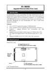
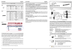
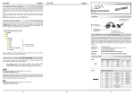
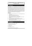
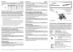
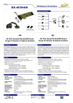
EX-48052
2S RS422/485 Mini PCIe Card
1. Introduction
Congratulation on your purchasing this high performance Mini PCI
Express (Mini PCIe) RS422/485 serial card. The card is high speed PCI
Express bus based and plug-and-play compliant. Both its enhanced
serial ports (256-byte deep FIFO) are jumper-configurable for RS422,
4-wire RS485 and 2-wire RS485 modes.
Features:
Full x1 Mini PCI Express Throughput, 250Mbytes/sec
Fully Compliant with PCI Express Base Specifications, Revision 1.1
Supports RS485 Auto Transceiver Turn Around by Unique Featured
ATTATM Hardware
Supports 2 DB9-male Connectors over Flat Cables
Support 4-wire RS422/485 and 2-wire RS485 Modes
Supports RS422/485 Speed up to 921.6Kpbs
9-bit Data Framing, as well as 5,6,7 and 8bits
Supports Win2000, XP, 2003, 2008, Vista, Win 7 and Linux
2. Board Layout
J2: S1, 1’st
RS422/485 port
Mini PCIe
golden
fingers
Pin #1
JP4: S2
Terminator
Enable/Disable
JP3: S1
Terminator
Enable/Disable
J5: factory use
only, do not
install any jumper
J3: S2, 2’nd
RS422/485 port
Pin #1
Pin #1
JP2: S2 mode
settings
JP1: S1 mode
settings
1
2S RS422/485 Mini PCIe Card
3. Jumper Settings
There are 2 sets of the jumpers to set the settings for port 1 (S1) and port
2 (S2) respectively.
Mode Selection Jumper: JP1 for S1, JP2 for S2
Termination Resistor Enable/Disable Jumper: JP3 for S1, JP4 for S2
1. Mode Settings:
JP1 (for S1)
JP2 (for S2)
2.
Description
485-2W
485-4W
422
RS485 2-wire mode
(Default)
485-2W
485-4W
422
RS485 4-wire mode
485-2W
485-4W
422
RS422 mode
Termination
Resistor
Enable/Disable:
This
jumper
enables/disables the 120 Ohm termination resistor between
DATA+ and DATA- of the RS485 transceiver:
JP3 (for S1)
JP4(for S2)
Description
ON OFF
Termination Resistor Disabled
(Default)
2
2S RS422/485 Mini PCIe Card
ON OFF
Termination Resistor Enabled
4. Installing the Mini PCIe Card
1.
Remove the Mini PCIe card from its protective antistatic
packaging, remove the screw holding the Mini PCIe card to the
motherboard and insert the new Mini PCIe card into the socket.
Mini PCIe Socket
2.
Put the Mini PCIe card onto the motherboard and attach it with
the screw.
Holding screw
3.
Install the serial flat cables. Please mind the pin 1 position to
match with the cable’s red color wire.
3
2S RS422/485 Mini PCIe Card
Red wire indicates pin 1
5. Software Installation
To install the Windows drivers, there are two methods, one is to run the
setup utility (StnSetup.exe) in each corresponding folder. The other one
is by the Windows’ driver installation Wizard. We recommend you run
the setup utility. It will be simpler. However, PLEASE REFRESH HARDWARE
OR REBOOT THE SYSTEM IN CASE YOUR DRIVER DID NOT TAKE EFFECT
AFTER RUNNING THE SETUP UTILITY.
The drivers are shipped in the following folders on the driver CD:
E:\IO\MOSCHIP\MCS99xx
Drivers are in each
corresponding folder
Driver Uninstalling Program
Driver Installing Program
4
2S RS422/485 Mini PCIe Card
6. Uninstalling the Software Drivers
In some cases, you may want to uninstall the drivers. To remove the
drivers that already installed for Windows, there are two methods:
1.
Run (double click) the uninstall program (for example
MOSCHIP_StnUninst.exe) in each Windows’ folder on the
supplied driver CD, it is usually in the same folder as the
StnSetup.exe utility:
2.
Go to Windows’ Control Panel’s Add/Remove Program to
remove the drivers.
7. RS422/485 Pin Assignments and Cable Wiring
DB9-Male Pin Assignment:
9 Pins
1
2
3
4
5
6
7
8
9
Signal
TXD- (DATA-)
TXD+ (DATA+)
RXD+
RXDGND
NC
NC
NC
NC
NC = No connection
RS422 Cable Wiring:
DB9
1
2
3
4
5
(RS422, PCIe Card)
TXDTXD+
RXD+
RXDGND
(RS422 Device)
1 TXD2 TXD+
3 RXD+
4 RXD5 GND
5
2S RS422/485 Mini PCIe Card
RS485 (2-wire) Cable Wiring:
DB9
1
2
3
4
5
(485, PCIe Card)
DATADATA+
NC
NC
GND
(RS485 Device)
1 DATA2 DATA+
3 NC
4 NC
5 GND
8. Environmental Specifications
Power requirements:
5V DC, 450mA (max)
Operating temp.:
0 to 558C (32 to 1318F)
Operating humidity:
5 to 95% RH
6