1
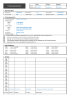
Easy Setup Guide Specification
47WV30MS/47WV30BR/
47WV30BS/47WV30BAAM/ 47WV30-BAAL
SUFFIX World Wide
2.
관 리 자
MK PARK H.J LEE
12.06.15 12.06.15
1. Model Description
MODEL
담 당
BRAND
Product Name
LG
Part No.
No
JO KIM
12.06.15
MFL67559901
(1207-REV01)
Signage
Printing Specification
1. Trim Size (Format) : 172 mm x 243 mm
2. Printing Colors
(
)
Cover : 1 COLOR (BLACK)
Inside : 1 COLOR (BLACK)
3. Stock (Paper)
Cover : Coated paper, Snow White 150 g/㎡
Inside : Uncoated paper, 백상지 60 g/㎡
4. Printing Method : Off-set
5. Bindery : Perfect bind
6. Language : English/Czech/Spanish/French/German/Greek/Italian/Polish/Slovak/Portuguese (10)
7. Number of pages : 280 pages
N
O
T
E
S
3
3.
* This part contain Eco-hazardous substances (Pb, Cd, Hg, Cr6+, PBB, PBDE, etc.) within LG
standard level, Details should be followed Eco-SCM management standard[LG(56)-A-2524].
Especially, Part should be followed and controlled the following specification.
(1) Eco-hazardous substances test report should be submitted
when Part certification test and First Mass Production.
(2) Especially, Don’t use or contain lead(Pb) and cadmium(Cd) in ink.
Special Instructions
(1) Origin Notification
* LGEIN : Printed in Indonesia
* LGESP : Printed in Brazil
* LGEND : Printed in China
4.
* LGEWA : Printed in U.K
* LGEMX : Printed in Mexico
* LGEIL : Printed in India
* LGEMA : Printed in Poland
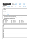
Changes
8
7
6
5
4
3
2
1
REV.
NO.
Jul./03/12
MK.Park
EKMC700023
MM/DD/YY SIGNATURE CHANGE NO.
Modify the Polish language.
CHANGE
CONTENTS
Pagination sheet
Total pages : 280 pages
Front cover
English
2
3
…
ČESKY
2
3
…
…
…
27
ESPAÑOL
2
3
…
…
…
27
FRANÇAIS
2
3
…
DEUTSCH
2
3
…
…
…
27
ΕΛΛΗΝΙΚΑ
2
3
…
…
…
27
ITALIANO
2
3
…
…
…
27
2
3
…
…
…
27
2
3
…
2
3
…
POLSKI
SLOVENČINA
PORTUGUÊS
…
…
…
…
…
…
…
…
27
27
27
27
Back cover
ENG
ENGLISH
Easy Setup Guide
MONITOR SIGNAGE
Please read this manual carefully before operating your set and retain
it for future reference.
MONITOR SIGNAGE MODELS
47WV30MS
47WV30BR
47WV30BS
47WV30-BAAM
47WV30-BAAL
P/NO : MFL67559901(1207-REV01)
Printed in Korea
www.lg.com
2
PRECAUTION
PRECAUTION
ENGLISH
ENG
Precaution in movement
Adhere to the warning signs printed on the Box.
Do not Clamp.
Do not drop from stacking.
Do not drop from clamping.
4 Persons needed for transport
2 Persons needed for transport
Do not transport horizontally.
Load with care.
Do not drop from carrying.
Don’t tumble the Set box sideward down.
Don’t lie on or lean on the Set box.
PRECAUTION
3
Precaution in Handling
CAUTION
This way up/ Fragile/ Keep away from rain/ Stacking limit 4.
ENG
ENGLISH
Move the Set as a team of 2 persons. When you move the bare Set, please use one hand on grabbing the
handle and the other support under the Set.
4
PRECAUTION
Causes & Phenomena of the Line Defect
ENGLISH
ENG
The line defect would occur on your Set if you strike on the edge of the Set.
LOG (LINE ON GLASS) DEFECT
Shock on Module Left/Top Corner Left/Top LOG Crack Horizontal Line Defect
LOG (LINE ON GLASS) DEFECT
Source PCB
Source PCB
COF Cable
COF Cable
Shock on Module Top Side Top COF Crack Vertical Line Defect
Shock on Module Left Side Left COF Crack Horizontal Line Defect
PRECAUTION
5
CAUTION
ENG
ENGLISH
Panel
Panel
Panneau
Panello
Panel
Panel
10 cm
10 cm
20 cm
10 cm
10 cm
Be careful not to collide the sets with
the floor or with each other. Install in
the space with enough airflow.
6
ASSEMBLING AND PREPARING
ASSEMBLING AND PREPARING
ENGLISH
ENG
Unpacking
Check your product box for the following items. If there are any missing accessories, contact the local
dealer where you purchased your product. The illustrations in this manual may differ from the actual product
and accessories.
Power Cord
RGB Cable
DVI Cable
CD (Owner's Manual, SuperSign
Program, SuperSign Manual) /
Card
POWER
ENERGY
MONITOR
INPUT
OFF
ON
SAVING
.,!
GHI
PQRS
1/a/A
ABC
JKL
TUV
-*#
DEF
IR Receiver
MNO
Guide bracket
Ring Core
WXYZ
CLEAR
MARK
ARC
P
PSM
BRIGHT A
NESS G
E
MUTE
MENU
AUTO
S.MENU
OK
BACK
TILE
EXIT
ID
ON
OFF
M4 x 10L
Screw (4ea)
M6
Screw (4ea)
Cable holder
(2ea)
Power cable holder
U-shaped fixture
RS-232C Cable
Remote control and Batteries
CAUTION
Do not use any pirated items to ensure the safety and product life span.
Any damages or injuries by using pirated items are not covered by the warranty.
NOTE
The accessories supplied with your product may vary depending on the model.
Product specifications or contents in this manual may be changed without prior notice due to upgrade
of product functions.
How to Use a Ring Core
A ring core reduces electromagnetic waves emitted from the IR receiver.
Loop the cable through the core once, before using it as illustrated.
Ring Core
ASSEMBLING AND PREPARING
7
Dimensions (Width x Height x Depth) / Weight
ENG
ENGLISH
1047 mm x 592 mm x 91.1 mm / 29 kg
To view the User’s guide
“Insert CD ROM” in Computer
CD-ROM will open automatically.(for Window only)
My computer
Digital_LG(CD-ROM)
Index.htm Open
Digital_LG(CD-ROM)
Manual folder
User's Guide Open
My computer
8
ASSEMBLING AND PREPARING
Installing the Product
ENGLISH
ENG
1
Cut Packing Strap of the Box.
3
Open the Box and remove the top packing.
5
Open the Poly Bag.
2
Cut Tape on the Box.
4
Remove the Upper Box.
6
Undress the Poly Bag.
ASSEMBLING AND PREPARING
7
9
8
ENG
ENGLISH
Lift up the Set using the SIDE/BACK Handle.
Remove Bottom packing when lifting up the Set.
9
With one hand under the set and the other hand grabbing the set, move the set.
10
Lay the back of the Set down on the table.
11
10
12
ASSEMBLING AND PREPARING
13
ENGLISH
ENG
Use the cushion or Pad when you lay the face of the Set downward.
14
15
Connect IR receiver to use remocon. And then, connect power code.
ASSEMBLING AND PREPARING
Remove the L-brackets from each corner of the
monitor before installing it.
Tiling Displays
How to Join Sets - Installing Set 1
*Example of 2 x 2 tiling
The numbers assigned in this example (#1,
#2, #3, #4) are used to demonstrate the
installation procedure to ensure it is easy to
follow. These numbers have nothing to do
with the Set ID that is used to operate the
remote control.
Set the guide bracket into the bracket groove
using screws and mount the set to the wall
mount plate or the wall.
Guide bracket
NOTE
Keep the removed L-brackets and use them
when moving the monitor later.
Wall mount plate
CAUTION
When you connect Monitor sets for
multivision, you may find that the screen
color is not the same across all the Monitor
sets. If you want to adjust the screen color
manually, please refer to the Installation
Manual.
When you install multiple Monitor sets onto
a wall, attach the IR Receiver to all the
sets, or use an RS-232C cable to connect
them and then attach the IR Receiver to the
first set.
<Rear view of the set with the wall mount plate>
Screws for fixing the
VESA wall mount
Guide bracket
Screws for fixing the
guide bracket
Wall mount plate
The wall mount plate is shaded in gray in the
illustration to help you see it.
ENG
ENGLISH
Remove L-brackets before
Installation
11
12
ASSEMBLING AND PREPARING
How to Join Sets - Installing Set 2
ENGLISH
ENG
Join Set 2 to Set 1 using the guide brackets
on the top side of Set 1 and mount the two
sets to the wall mount plate or the wall.
Remove the guide brackets after mounting
the sets.
<The sets joined with the guide
brackets>
How to remove the guide brackets
Unscrew the guide bracket screws from
the rear of the set and remove the guide
brackets.
Once the screws are removed, the guide
brackets will drop. You need to remove them
through the gap on the sides of the set.
This can be done only when there is enough
space between the set and the wall mount
plate or the wall to unscrew the screws.
(Please check whether there is enough
space to remove the screws before fixing the
guide brackets.)
Guide bracket
<Rear view of the set with the wall
mount plate>
<The sets after removing the guide
brackets>
<Removing the guide bracket through
the side gap>
Remove the
guide brackets
ASSEMBLING AND PREPARING
13
How to Join Sets - Installing Set 3
#2
#1
#3
<Joined Sets 1 and 2>
<Set 3 to be joined>
Minimize the space between the sides of the sets using the U-shaped fixture.
When the sets are joined with the minimum amount of space between them, firmly mount them to the wall
mount plate or the wall.
When the sets are firmly mounted to the wall, remove the U-shaped fixtures.
U-shaped fixture
U-shaped fixture
ENG
ENGLISH
Fix the guide brackets to Set 3 following the steps above, and loosely mount the set to the wall mount
plate or the wall.
14
ASSEMBLING AND PREPARING
How to Join Sets - Installing Set 4
ENGLISH
ENG
Loosely mount Set 4 to the wall mount plate or the wall and minimize the space between the sets using
the U-shaped fixtures.
When Set 4 is firmly mounted to the wall, remove the U-shaped fixtures.
Remove the guide brackets. See <How to Join Sets - Installing Set2,3>.
Now the 2 x 2 tiling is complete.
You can tile in various combinations, such as 3 x 3.
Set 4 joined to the rest of the sets
(2 x 2 tiling)
Wall mount plate or wall
Display set
NOTE
The guide brackets for tiling should only be used to join sets and should be removed once they are joined.
The guide brackets should only be used as the assisting tool when tiling sets. The load applied to each set
should be supported by the wall mount plate or the wall using a VESA wall mount (800 x 400).
(Each set must be firmly mounted to the wall mount plate or the wall.)
The guide brackets must be removed once the sets are joined. When joining the sets without removing the
guide brackets, extra caution is required to prevent damage due to the set weight.
The U-shaped fixtures must also be removed after mounting the set to the wall mount plate or the wall.
You may mount the set without using the guide brackets or the U-shaped fixtures; this does not affect the
performance of the device.
15
REMOTE CONTROL
REMOTE CONTROL
ENG
ENGLISH
The descriptions in this manual are based on the buttons of the remote control. Please
read this manual carefully and use the Monitor set correctly.
POWER
ENERGY
MONITOR
INPUT
OFF
ON
SAVING
1
4
7
.,!
To replace batteries, open the battery cover, replace
batteries (1.5 V AAA) matching and ends to the
label inside the compartment, and close the battery
cover. To remove the batteries, perform the installation
actions in reverse.
2
5
8
0
ABC
GHI
PQRS
1/a/A
JKL
TUV
-*#
3
6
9
DEF
MNO
WXYZ
CLEAR
MARK
ARC
P
PSM
BRIGHT A
NESS G
E
MUTE
MENU
AUTO
S.MENU
OK
BACK
TILE
EXIT
ID
ON
OFF
CAUTION
Do not mix old and new batteries, as this
may damage the remote control.
Make sure to point the remote control at the
remote control sensor on the Monitor.
Power On / Off
Switches the set on from
standby or off to standby.
Monitor On / Off
Turn off the monitor and then
turn it back on.
Energy Saving
Adjust the Energy Saving
mode of the SET.
INPUT
If you press the button once, the
following Input Signal Window
will appear. Select the signal
type you want using the button.
POWER
ENERGY
MONITOR
INPUT
OFF
ON
SAVING
1/a/A
This button selection is not
applicable.
.,!
GHI
PQRS
1/a/A
PSM
Selects the Picture Status
Mode.
ABC
JKL
TUV
-*#
Number and Alphabet
Type numbers.
The alphabet selection is not
applicable.
DEF
MNO
Clear
This button selection is not
applicable.
WXYZ
CLEAR
MARK
ARC
P
PSM
BRIGHT A
NESS G
E
Volume Up/Down
Adjusts the volume.
MUTE
MENU
AUTO
S.MENU
ARC
Selects the Aspect Ratio Mode.
BRIGHTNESS
Moves to the previous or next
screen.
MUTE
Switches the sound on or off.
16
REMOTE CONTROL
POWER
ENERGY
MONITOR
INPUT
OFF
ON
SAVING
ENGLISH
ENG
1
4
7
.,!
2
5
8
0
ABC
GHI
PQRS
1/a/A
JKL
TUV
-*#
3
6
9
DEF
MNO
WXYZ
CLEAR
MARK
ARC
P
PSM
BRIGHT A
NESS G
E
MUTE
MENU
AUTO
S.MENU
OK
BACK
TILE
EXIT
ID
ON
MENU
Selects a menu.
Clears all on-screen displays
and returns to Set viewing
from any menu.
Up/Down/Left/Right
Allows you to navigate the
on-screen menus and adjust
the system settings to your
preference.
AUTO
Automatically adjusts picture
position and minimizes image
instability.(RGB input only)
NESS
ID ON/OFF
Allows you to set the Picture
ID or turn it off. Use this
button to control the individual
monitors connected in RS232C mode. (It works properly
only when Set IDs are
assigned.)
USB Menu control
Controls media playback.
E
MUTE
MENU
OK
Accepts your selection or
displays the current mode.
BACK
Allows the user to move
back one step in an interactive
application.
OFF
AUTO
S.MENU
S.MENU
(SuperSign Menu Key)
This button selection is not
applicable.
OK
BACK
TILE
ID
ON
OFF
EXIT
EXIT
Clears all on-screen displays
and returns to Monitor set
viewing.
TILE
Selects the TILE Mode.
MAKING CONNECTIONS
17
MAKING CONNECTIONS
1 Find an external device you want to connect to your Monitor set shown on the following illustration.
2 Check the connection type of the external device.
3 Go to the appropriate illustration and check the connection details.
DVD
HD Receiver
HDMI
Component
AV
HDMI
Component
AV
Speaker
USB
Memory storage
PC
Camcorder/Camera
HDMI
Component
AV
HDMI
DVI
RGB
Gaming device
HDMI
Component
AV
NOTE
If you connect a gaming device to the Monitor set, use the cable supplied with the gaming device.
AV(CVBS) can be supported only in 47WV30BR and 47WV30MS models.
NOTE
RGB
DVI
Connect the signal
input cable and tighten
it by turning the screws
clockwise.
When connecting an HDMI
cable as illustrated, remove
the screw on the HDMI
connector first.
ENG
ENGLISH
Connect various external devices to the ports on the Monitor set’s back panel.
AUDIO OUT
DVI OUT
HDMI OUT
(CONTROL)
(RGB/DVI)
AUDIO
DVI IN
CONTROL IN
REMOTE
DVI OUT
USB
RGB OUT
AUDIO OUT
/DVI
RGB IN
RGB OUT
CONTROL IN
REMOTE
(RGB/DVI)
AUDIO
LAN
PB
VIDEO
PR
AV IN
L
AUIDO
COMPONENT IN
R
(8Ω)
SPEAKER
ENGLISH
ENG
RS-232C
18
MAKING CONNECTIONS
< 47WV30MS/47WV30BR >
RED
WHITE
RED
BLUE
GREEN
CONTROL IN
REMOTE
(RGB/DVI)
AUDIO
DVI IN
USB
RGB OUT
AUDIO OUT
/DVI
RGB IN
RGB OUT
CONTROL IN
REMOTE
(RGB/DVI)
AUDIO
LAN
AUDIO
VIDEO
PB
PR
L
COMPONENT IN
BLUE
AUDIO OUT
DVI OUT
R
AUDIO
WHITE
DVI OUT
HDMI OUT
(CONTROL)
(8Ω)
SPEAKER
RED
ENG
ENGLISH
RS-232C
MAKING CONNECTIONS
RED
GREEN
19
< 47WV30BS/47WV30-BAAM/47WV30-BAAL >
20
MAKING CONNECTIONS
Connecting to a USB
Connecting the Power code
ENGLISH
ENG
or
2
1
Connecting to the LAN
LAN connection
Power button
A Using a router(Switching Hub)
LAN
POWER
ENERGY
MONITOR
Switching Hub
INPUT
OFF
ON
SAVING
Product
.,!
ABC
DEF
PC
NOTE
B Using the Internet.
POWER
MONITOR
ON
ENERGY
INPUT
INPUT
OFF
SAVING
1 .,! 2 ABC 3 DEF
Select an input signal.
AV
Component
RGB
HDMI
DVI-D
MAKING CONNECTIONS
21
Daisy Chain Monitors
ENG
ENGLISH
RGB Cable
15-pin D-Sub Signal Cable
(Max 3m)
Set 1
Set 2
Set 3
Set 4
DVI Cable
DVI Cable
(Max 3m)
DVI-OUT
DVI-IN
Set 1
DVI-OUT
Set 2
DVI-IN
DVI-OUT
DVI-IN
Set 3
NOTE
"Input signal may be degraded or lost when multiple monitors are connected. For DVI, in general, up
to 12 monitors can be connected via the DVI Out port (at the recommended resolution) if the signal
is stable and there is no cable loss. (If you want to connect more than this number of monitors, we
recommended that you use a distributor.)
When the tile mode is configured via DVI cables, only the monitor that receives first signals can play
HDCP-encrypted content. (The DVI Out port does not support HDCP).
If the signal cable between the product and your PC is too long, make sure to use the DVI (RGB)
booster or DVI (RGB) optical cable.
If input signals are received through the HDMI/DP cable, multiple monitors cannot be connected via
the DVI Out port"
22
MULTIVISION CONFIGURATION
MULTIVISION CONFIGURATION
ENGLISH
ENG
Function Setting
3 Set ID setup for each set.
1 IR Receiver connection.
OPTION
Move
OK
• Language
AUDIO
(RGB/DVI)
• ISM Method
: Normal
• DPM Select
: Off
• Fail Over
: Off
• Factory Reset
• Set ID
REMOTE
CONTROL IN
ꔋ
:1
• Tile Mode
• Portrait Mode
• Fan
• Product/Service Info.
4 IR Receiver removal for all sets except for Set 1.
5 RGB connection.
RGB OUT
RGB IN
2 Connecting the Power code
2
1
PC
MULTIVISION CONFIGURATION
23
6 Connect the Monitor sets, in series, using an RS-232C cable.
ENG
ENGLISH
RS-232C Cable
PC
Set 1
Set 2
7 Installation Menu setup.
Installation Menu (V 2.21)
LG Digital Signage Setup
White Balance Adjust
Password Change
Configuration Cloning
MCU Version V1.02.08
OK
8 Tile Mode setup.
OPTION
Move
OK
• Language
• ISM Method
: Normal
• DPM Select
: Off
• Fail Over
: Off
• Factory Reset
• Set ID
:1
• Tile Mode
• Portrait Mode
• Fan
• Product/Service Info.
ꔋ
Set 3
Set 4
24
MULTIVISION CONFIGURATION
Setting the Installation Menu
ENGLISH
ENG
1 If you press the MENU button on the remote
control for more than five seconds, the main
menu appears and then disappears. The input
data is also displayed in the upper left corner of
the screen.
RGB
LG Digital Signage Setup (V2.21)
▲
• Menu Display
• OSD Display
• Min Volume
Yes
• Max Volume
• Power On Operation
• Input Source
• Volume
• Aspect Ratio
• Intelligent Auto
100
Yes
0
No
OFF
OFF
OFF
Yes
▼
OK
2 Press the "0" button four times. Press the OK
LG Digital Signage Setup (V2.21)
▲
button.
• Factory Reset
1
4
7
.,!
GHI
PQRS
1/a/A
2
5
8
0
TUV
3
6
9
-*#
CLEAR
ABC
JKL
No
DEF
MNO
WXYZ
3 When the Installation Menu is displayed, select
the item you want.
OK
Installation Menu (V 2.21)
LG Digital Signage Setup
White Balance Adjust
Password Change
Configuration Cloning
MCU Version V1.02.08
OK
LG Digital Signage Setup (V2.21)
Signage Mode Operation
• 15 Min Force Off
• 4 Hours Off
• Wake On LAN
◄
Yes
►
Yes
Yes
No
• Total Set ID
• DPM
• Software Update
• Power On Status
• Input Source Change
1
Yes
No
STD
Yes
▼
OK
MULTIVISION CONFIGURATION
Decide to work all functions of
'Signage Mode Operation' or not.
15Min Force
Off
Turns off the monitor if there is no
input for more than 15 minutes.
"No" is the recommended default
value setting.
4 hours off
Turns off the monitor if there is no
input on the remote control for more
than four hours.
"No" is the recommended default
value setting.
Wake On LAN
Turns on the monitor remotely using
LAN.
Total Set ID
Sets the maximum value for picture
IDs.
DPM
Enters energy saving mode if there is
no input signal.
Software
Update
Sets whether to use NSU (Network
Software Update).
Power On
Status
Decide to select working status
of Monitor Set when turn on main
power.
Input Source
Change
Decide to change input source or not
by setting 'Input Source Change' as
Yes(Change possible) or No(Change
impossible).
Menu Display
MENU key does not work if 'Menu
Display' is set to No.
OSD Display
Decide to display OSD or not by
setting 'OSD Display' as Yes(Mark)
or No(No Mark).
Min Volume
Decide 'Min Volume' between
changing range 0 to 100.
Max Volume
Decide 'Max Volume' between
changing range 0 to 100.
Power On
Default
With the power turned on, you can
set the 'Input Source' and 'Volume'
options.
Input Source
Set whether it is turned on by the
set input source or by the last stored
input source.
Volume
This sets whether to apply the
Volume Level or not when the power
is turned on.
Aspect Ratio
With the power turned on, you can
set the 'Aspect Ratio' option with the
pre-defined value.
Intelligent Auto
If the setting is Yes, Display is
automatically arranged through
resolution size when you change the
resolution at the first.
Factory Reset
If it is set to No, 'Factory Reset' under
OPTION is disabled.
ENG
ENGLISH
Signage Mode
Operation
25
26
MULTIVISION CONFIGURATION
Setting the Tile Mode
• 2X1:
ENGLISH
ENG
• 2X2:
When using four monitors
When using two monitors
Tile Mode Off: An input image is not
enlarged, and the same image is shown on
all connected monitors.
Tile Mode On: An input image is enlarged
according to the value in the H. Set Count
and V. Set Count fields.
ID 2
ID 1
In Tile Mode you can view an image in a larger
scale by connecting multiple monitors.
Tile ID
• 3X3:
When using nine monitors
OPTION
Move
OK
ID 1
ID 2
ID 3
ID 4
ID 5
ID 6
ID 7
ID 8
ID 9
• Language
• ISM Method
: Normal
• DPM Select
: Off
• Fail Over
: Off
• Factory Reset
• Set ID
:1
• Tile Mode
ꔋ
• Portrait Mode
• Fan
• Product/Service Info.
• 4X4:
When using 16 monitors
ID 1
ID 2
ID 3
ID 4
ID 5
ID 6
ID 7
ID 8
ID 9
ID 10
ID 11
ID 12
ID 13
ID 14
ID 15
ID 16
ID 1
ID 2
ID 3
ID 4
MULTIVISION CONFIGURATION
27
Setting the Picture ID
2 If you press the left/right buttons or press the
ON button repeatedly, the Picture ID cycles
through OFF and 1 to 4.Assign the ID you
want.
Picture ID
Off
Close
AUDIO
(RGB/DVI)
RS-232C OUT
RS-232C OUT
RS-232C OUT
RS-232C IN
RS-232C IN
RS-232C IN
REMOTE
CONTROL IN
IR Receiver
Picture ID
Off
Close
2X2 Multi-Vision (Total Set ID: 4)
Set IDs are assigned as shown in the picture.
1 Press the ID On (Red) button on the remote control.
BACK
TILE
ID
ON
OFF
EXIT
If you assign the Set ID to each set with
multi-vision, and then assign the Picture ID
using the red button on the remote control,
the key command is displayed for the set
with the same Set ID and Picture ID. A set
with different Set IDs and Picture IDs cannot
be controlled by IR signals.
Refer to the Set ID on page 46 for assigning
a Set ID.
The maximum value of the Picture ID can be
set in the Total Set ID menu.
Please refer to the Installation Manual for
more information on the assignment of a
Total Set ID.
NOTE
For example, if the Picture ID is assigned
to 2, the upper right display (Set ID: 2) can
be controlled by IR signals.
For each set, you can change the settings
for the PICTURE, AUDIO, TIME, OPTION,
NETWORK and MY MEDIA menus or the
hot keys on the remote control.
If you press the ID OFF (Green) button,
the Picture IDs for all sets are turned off. If
you then press any button on the remote
control, all sets will start working again.
The Picture ID function may not work during MY MEDIA operating.
ENG
ENGLISH
Picture ID is used to change the settings of a
specific set (display) using a single IR receiver for
multi-vision. The set receiving the IR signal communicates with another set via the RS232 connector. Each set is identified by a Set ID. If you assign the Picture ID using the remote control, only
displays with the same Picture ID and Set ID can
be controlled remotely.