1
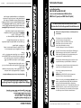
Byk-Gulden-Str. 22 · D-78224 Singen
Phone: +49 (0) 7731 - 8673-0 · Fax: +49 (0) 7731 - 8673-17
Email: [email protected] · www.spaun.com
Technische Verbesserungen, Änderungen im Design und Irrtümer vorbehalten.
104554/01.12
Elektronische Geräte gehören nicht in den Hausmüll, sondern
müssen – gemäß der Richtlinie DIN EN 50419 (entspricht dem
Artikel 11(2) der Richtlinie 2002/96/EG) des Europäischen
Parlaments und des Rates vom 27. Januar 2003 über Elektro- und
Elektronik -Altgeräte - fachgerecht entsorgt werden. Bitte geben
Sie dieses Gerät am Ende seiner Verwendung zur Entsorgung an
den dafür vorgesehenen öffentlichen Sammelstellen ab.
Die zulässige Umgebungstemperatur beträgt:
-20° C ... +50° C.
WARNUNG (nur SBK 5502 NF): Oberflächentemperatur
ist 20 Kelvin höher als Umgebungstemperatur.
Alle Komponenten sind zum Verbinden mit dem Hauptpotentialausgleich mit einer Erdungsklemme ausgestattet.
Die Basisgeräte und Multischalter erfüllen die erhöhten Schirmungsmaß-Anforderungen gemäß EN 50083-2, Güteklasse A.
Technical Advice
for the System Launch Amplifiers
SBK 5502 NF and SBK 5503 NFI
and the Cascadable Multiswitches
SMK 55xx3 F (passive) and SMK 55xx3 FA (active)
Always remove mains cable before opening the device!
Please follow the safety instructions enclosed!
Important: please observe the following instructions
Installation is only permitted in dry rooms and upon
a non-combustible surface. Ensure that there is adequate
air circulation.
Wall mounting only with power supply housing on the left
or on the right side (horizontal mounting).
SPAUN electronic confirms the keeping of the EMC
requirements in accordance to the EU product norm
EN 50083-2 and the keeping of the safety requirements in
accordance to the EU product norm EN 60728-11 by the
CE sign.
Mit der CE-Kennzeichnung bestätigt SPAUN die Einhaltung der
EMV-Anforderungen entsprechend der EU Produktnorm EN
50083-2 und die Einhaltung der Sicherheitsanforderungen entsprechend der EU Produktnorm EN 60728-11.
The Launch amplifiers and the multiswitches meet
the more stringent screening requirements according
to EN 50083-2, quality grade A.
Telefon: +49 (0) 7731 - 8673-0 · Telefax: +49 (0) 7731 - 8673-17
E-Mail: [email protected] · www.spaun.de
All components are equipped with an earthing terminal for
connecting to the main potential equalization.
Byk-Gulden-Str. 22 · D-78224 Singen
Die Montage ist nur in trockenen Räumen und
auf nicht brennbarem Untergrund zulässig.
Netzgespeiste Geräte ausschließlich waagerecht
(Netzteil links oder rechts) montieren, um eine
ausreichende Luftzirkulation zu erzielen.
Vorsicht bei Montage in Schalt- bzw. Zählerkästen!
Wichtig: alle nachfolgenden Hinweise vollständig durchlesen
und beachten.
Vor Öffnen des Geräts bitte Netzstecker ziehen!
Bitte beachten Sie die beiliegenden Sicherheitshinweise!
zu den Basisgeräten
SBK 5502 NF und SBK 5503 NFI
sowie zu den kaskadierbaren Multischaltern
SMK 55xx3 F (passiv) und SMK 55xx3 FA (aktiv)
Technische Hinweise
The permissible ambient temperature range is:
-20° C ... +50° C (253 K ... 323 K).
WARNING (only SBK 5502 NF): surface temperature
is 20 Kelvin higher than the ambient temperature !
Electrical and electronic equipment are not household waste
- in accordance with the European directive EN 50419 (corresponds to the article 11(2) of the guideline 2002/96/EC) of the
European Parliament and the Council of January, 27th 2003 on
used electrical and electronic equipment, it should be disposed properly. Please, on the end of its life cycle, take this
unit and dispose it on designated public collection points.
Specifications and design are subject to change due to our policy of continual technical improvement.
104554/01.12
TM
2
Einstellhinweise:
Stromversorgung LNB
Schalterstellungen:
Für die LNB-Fernspeisung sind 3 Betriebsarten wählbar:
22 kHz:
Wie Schalterstellung 18 Volt, jedoch sind die High-Band Eingänge
mit 22 kHz moduliert (Betriebsart für QUAD).
-10 dB
Standby
Vertical IF inputs carry 12 volts, horizontal IF inputs carry
18 volts.
18 V:
All 4 IF inputs carry 12 volts remote power supply (for
Quattro LNB).
12 V:
3 operation modes can be chosen for the LNB remote power supply:
Power Supply to LNB
Setting instructions:
TM
2
18 V
22 kHz
Same as controller position 18 volts, but the high-band
inputs are 22 kHz modulated (for QUAD-LNB).
Bitte beachten Sie den Anleitungsteil „Terrestrik“!
22 kHz:
Um den Pegel der terrestrischen oder BK-Signale anzupassen, sind die
Basisgeräte mit einem Pegelsteller ausgestattet. Die Eingangspegel können
im aktiven Betrieb um 0...10 dB reduziert werden.
22 kHz
12 V
18 V
passiv
-10 dB
Dauerbetrieb/
Always On
Terr.
The controller position does not affect the control signals of
the receiver !
The adequate LNB remote power voltage can be set for
operation modes “standby” or “Always on”.
High-Band
Low-Band
Das Basisgerät SBK 5503 NFI verfügt über Synchronpegelsteller, um die
unterschiedlichen Pegel der verschiedenen Bänder (Low-Band; High-Band)
anzugleichen. Pro Band steht ein Regler zur Verfügung. Die Eingangspegel
können um 0...10 dB reduziert werden. Die Version SBK 5502 NF besitzt für
jeden SAT-ZF-Eingang separate Pegelsteller. Stellbereich: 0 ... -8 dB.
Previous versions only with “standby” mode.
Please pay attention to the label.
Synchron
The LNB remote current must not exceed a total of 0,6 A and the
maximum permissible current per socket must not exceed 0,4 A for the
SBK 5502 NF and 0,5 A for the SBK 5503 NFI.
Synchron
Input Levels
Eingangspegel
Synchron
Der LNB-Fernspeisestrom darf insgesamt 0,6 A und der maximal zulässige Strom auf einer Buchse darf 0,4 A beim SBK 5502 NF und 0,5 A beim
SBK 5503 NFI nicht überschreiten.
Synchron
Bei Vorgängerversionen nur Standby Betrieb möglich.
Bitte beachten Sie das Geräteetikett.
High-Band
Die Schalterstellung hat keinen Einfluss auf die Steuersignale des Receivers!
Die zutreffende LNB-Fernspeisespannung kann für die
Betriebsfunktionen “Standby” oder “Dauerbetrieb” =Always On
eingestellt werden.
Low-Band
Dauerbetrieb/
Always On
The SBK 5503 NFI has a synchronous level attenuator in order to match the
different levels of the various bands (low band, high band). There is one controller per band. The input levels can be reduced by 0 ... 10 dB.
The SBK 5502 NF has a separate level attenuator for each SAT-IF-input.
Level adjustment range: 0 ... -8 dB.
22 kHz
12 V
18 V
12 V
Die vertikalen ZF-Eingänge führen 12 Volt und die horizontalen
ZF-Eingänge führen 18 Volt.
Terr.
18 V:
The launch amplifiers are equipped with an adjustable attenuator in order to
adjust the level of the terrestrial or CATV signals.
The input levels can be reduced in active mode by 0 ... 10 dB.
18 V
22 kHz
passiv
12 V
Alle 4 ZF-Eingänge führen 12 Volt Fernspeisung (Betriebsart für
Quattro LNB).
Please take note of the „Terrestrial“ section of the instructions.
Standby
12 V:
TM
3
Stromversorgung
Die Basisgeräte verfügen über ein internes, energiesparendes Schaltnetzteil.
Netzspannung AC: 100 ... 240 V / 47 - 63 Hz
Leistungsaufnahme (ohne LNB Versorgung):
SAT
SAT
SAT
SAT
Standby
aktiv + LNB
Standby
aktiv + LNB
Terr.
Terr.
Terr.
Terr.
passiv
passiv
aktiv
aktiv
SBK 5502 NF
SBK 5503 NFI
<3W
< 11 W
<7W
< 15 W
<9W
< 16 W
Standby-Funktion
Die Standby-Signalisierung erfolgt über Stammleitungsausgang 1. Bleibt dieser offen
oder wird mit einem DC-Trennglied (DCF 500) entkoppelt, ist das Basisgerät aktiviert
(interner Pull-Up).
Ein direkt angeschlossener kaskadierbarer Multiswitch oder ein Nachverstärker bringt das
Basisgerät zunächst in den Standby-Modus. Schickt ein Receiver eine Fernspeisespannung
an den Multiswitch, wird diese auf der Stammleitung 1 zum Basisgerät geleitet, wodurch
dieses aktiviert wird.
Nachverstärkerspeisung:
Die Basisgeräte SBK 5502 NF/5503 NFI stellen am Stammleitungsausgang 0 dauerhaft eine
Fernspeisespannung zur Versorgung eines Verstärkers oder einer aktiven Kaskade
zur Verfügung. Die SAT-ZF-Stammleitungsausgänge 2,3,4 führen nur dann eine
Fernspeisespannung, wenn das Basisgerät nicht im Standby-Modus ist. Die zulässige
Gesamtstromabgabe beträgt 650 mA jedoch max. 500 mA pro Buchse beim SBK 5502 NF.
Der SBK 5503 NFI hat eine zulässige Gesamtstromabgabe von 1000 mA. Das Basisgerät SBK
5503 NFI kann einen Nachverstärker NVF 5522 SR oder NVF 5523 SR speisen, das SBK 5502
NF darf nur mit dem NVF 5522 SR kombiniert werden.
Terrestrik:
SBK 5502 NF
Der terrestrische Eingang verfügt über einen Pegelsteller (Stellbereich -10 dB).
Der Verstärkerzug (47 … 862 MHz) ist durch eine integrierte Gegentakt-Endstufe BK-tauglich.
Die Terrestrik kann auch passiv durch geleitet werden. Dazu muss der Pegelsteller bis zum
Anschlag (PASIV) gegen den Uhrzeigersinn gedreht werden. Der terrestrische Verstärker ist
dann ausgeschaltet und die Durchgangsdämpfung beträgt 4 dB. Gleichzeitig erweitert sich der
Frequenzbereich auf 5 … 862 MHz; das bedeutet: Rückkanalfähig
SBK 5503 NFI
Der terrestrische Eingang verfügt über einen Pegelsteller ( Stellebreich -10 dB).
Der Verstärkerzug verfügt über einen BK-tauglichen aktiven Vorwärtsweg von 85 … 862 MHz
in Push-Pull-Technik (Verstärkung 25 … 31 dB). Der passive Rückweg von 5 … 65 MHz verfügt
über eine Dämpfung von 4 dB und somit ist auch dieses Basisgerät Rückkanalfähig.
Die terrestrischen Antennensignale müssen den Basisgeräten zur Vermeidung von Störungen
selektiv zugeführt werden.
To avoid any interference on the terrestrial signal it is necessary to feed the signals selectively.
SBK 5503 NFI
The terrestrial input has an adjustable attenuator ( -10dB level range).
The terrestrial amplifier stage support an active CATV compatible forward path from 85 … 862
MHz using push-pull technology (gain 25 … 31 dB). The passive return path between 5 … 65
MHz has a loss of 4 dB. The SBK 5503 NFI is return path compatible, too.
SBK 5502 NF
The terrestrial input has an adjustable attenuator ( -10dB level range).
The amplifier unit (47 … 862 MHz) is made CATV compatible by a push-pull final stage. The
terrestrial signal can also be passed through passively. To do this, the adjustable attenuator
must be turned counterclockwise as far as it will go. The terrestrial amplifier is then switched
off and the through loss is 4 dB. At the same time, the frequency range expands to 5 … 862
MHz; this means that the launch amplifier is return path compatible.
Terrestrial:
The SBK 5502 / SBK 5503 NFI launch amplifiers provide a continuous remote voltage at
trunkline output 0 for supplying a network repeater amplifier. SAT-IF trunkline outputs 2,
3, 4 then only provide a remote voltage when the launch amplifier is not in stand-by
mode. The maximum permissible total current delivery is 650 mA for the SBK 5502 NF
and there is a maximum of 500 mA per socket. The SBK 5503 NFI supports a maximum remote current of 1000 mA. The SBK 5503 NFI can feed a NVF 5522 SR or NVF 5523 SR repeater
amplifier, the SBK 5502 NF may only be combined with the NVF 5522 SR.
Repeater amplifier supply:
The stand-by signaling takes place over trunkline 1. The Launch Amplifier is activated if
the trunkline output remains open (internal pull-up) or if it is isolated by a DC blocker
(DCF 500). A directly connected, cascadable multiswitch or a network repeater amplifier
first brings the launch amplifier into standby mode. If a receiver sends a remote voltage to
a multiswitch then this is transmitted on trunkline 1 to the launch amplifier, which is thereby
activated.
Stand-by function:
Terr. aktive
SAT aktiv + LNB
Terr. aktive
SAT Standby
Terr. passive
SAT aktiv + LNB
Terr. passive
SAT Standby
< 15 W
<7W
< 11 W
< 16 W
<9W
-
<3W
SBK 5503 NF
SBK 5502 NF
The launch amplifiers have an internal, energy-saving, switched mode power supply.
Nominal voltage AC: 100 ... 240 V /47 - 63 V
Power consumption (without LNB remote power):
Power Supply
3
TM
TM
4
-20 ... +50 °C
> 50 dB
> 30 dB
-
SAT / Terr.
> 35 dB
> 55 dB
> 30 dB
> 30 dB
25 ... 31 dB
-
22 dB
4 dB
-
-
3.5 dB
Inputs / Outputs
SAT / Terrestrial
5/5
4/1
Model
TM
SBK 5502 NF
SBK 5503 NFI
4
300 x 130 x 52
-
220 x 130 x 52
24 ... 30 dB
Abmessungen in mm
-20 ... +50 °C
19 ... 23 dB
Umgebungstemperatur
118 dBμV
18 V / 1 A
109 dBμV
18 V / 650 mA
118 dBμV
600 mA
500 mA
110 dBμV
600 mA
400 mA
> 50 dB
-
> 30 dB
3W
Loss
Terr. passive:
5 ... 862 MHz
Loss
Terr. passive:
5 ... 65 MHz
Gain
Terr. active:
47 ... 862 MHz
Gain
Terr. active:
85 ... 862 MHz
Gain
SAT-IF:
950 ... 2200 MHz
Output level max.
47...862 MHz
60 dB IMA3 / EN 50083-3
Output level max.
950 ... 2200 MHz
35 dB IMA3 / EN 50083-3
Terr. active / SAT
<9W
-
7W
> 30 dB
-
Terr. passive / SAT
11 W
> 55 dB
< 16 W
> 35 dB
15 W
SAT / Terr.
100 ... 240 V / 47 – 63 Hz
> 30 dB
Selektion
100 ... 240 V / 47 - 63 Hz
Leistungsaufnahme
Terr. aktiv/SAT aktiv +LNB
Leistungsaufnahme
Terr. passiv/SAT aktiv +LNB
Leistungsaufnahme
Terr. aktiv/SAT standby
Leistungsaufnahme
Terr. passiv/SAT standby
LNB Gesamt-Fernspeisung
LNB Einzel-Fernspeisung
Stromabgabe
für Nachverstärker max.
Isolation
trunkline / trunkline
Netzanschluß U~
Mains power supply V~
> 30 dB
Terr. passiv / SAT
< 16 W
Terr. aktiv / SAT
15 W
118 dBμV
-
110 dBμV
11 W
118 dBμV
<9W
-
7W
-
-
109 dBμV
3W
24 ... 30 dB
Power consumption
Terr. active/SAT active +LNB
Power consumption
Terr. passive/SAT active +LNB
Power consumption
Terr. active/SAT standby
Power consumption
Terr. passive/SAT standby
19 ... 23 dB
600 mA
25 ... 31 dB
600 mA
-
LNB remote current
Verstärkung
Terr. aktiv:
85 ... 862 MHz
500 mA
-
400 mA
22 dB
Total single port current
Verstärkung
Terr. aktiv:
47 ... 862 MHz
18 V / 1 A
4 dB
18 V / 650 mA
-
Current for
post amplifier max.
-
Ambient temperature
3,5 dB
Entkopplung
Stamm / Stamm
5/5
4/1
Rejection
Eingänge / Ausgänge
SAT / Terrestrik
Dämpfung
Terr. passiv: 5 ... 862 MHz
Dämpfung
Terr. passiv: 5 ... 65 MHz
Verstärkung
SAT-ZF:
950 ... 2200 MHz
Ausgangspegel max.
47...862 MHz
60 dB IMA3 / EN 60728-3
Ausgangspegel max.
85 ...862 MHz
60 dB IMA3 / EN 60728-3
Ausgangspegel max.
950 ... 2200 MHz
35 dB IMA3 / EN 60728-3
300 x 130 x 52
SBK 5503 NFI
220 x 130 x 52
SBK 5502 NF
Dimensions (mm)
Modell
5
TM
Compatibility
Die Standby-Funktion des Basisgerätes wird von den Kaskadenkomponenten
unterstützt! Alle 5 Stammleitungen können Fernspeiseströme bis 1 A durchlassen.
20 mA für die passiven Kaskaden
75 mA für die aktiven Kaskaden.
Die Kaskadenkomponenten haben pro angeschlossenem Receiver
eine Stromaufnahme von
Die Stammleitungsausgänge der Kaskadenkomponenten sind mit
Abschlusswiderständen ZFR 75 DC abzuschließen. Diese DC-entkoppelten
Abschlusswiderstände liegen dem Basisgerät bei.
Die Komponenten können bei zentraler Verteilung untereinander mit den
Steckverbindern ZSV 2S verbunden werden. Ebenso können diese aber
auch voneinander entfernt als “Etagenverteilung” installiert werden.
Die Kaskaden sind Ergänzungskomponenten des Basisgerätes, um eine
Satelliten-ZF-Verteilanlage aufzubauen. Sie unterstützen die terrestrische
Signalverteilung und sind rückwegtauglich !
Die SMK 5543 FA verfügt als einzige nicht über einen externen DC-Eingang!
Wenn die aktiven Kaskaden ohne Steckernetzteil betrieben werden, funktioniert die Terrestrik nicht, sondern nur die SAT-ZF!
Wird ein Steckernetzteil (SNG 18/1000) an die DC Buchse der aktiven Kaskade angeschlossen, funktioniert die SAT-ZF und die Terrestrik einwandfrei!
Bitte beachten: Die aktiven Kaskaden können auch als „Stand-Alone“ Geräte genutzt werden!
• Die passiven Kaskaden sind nur verwendbar in Verbindung mit einem
Basisgerät SBK 55xx NFx.
SMK 55xx3 F und SMK 55xx3 FA
Kaskadierbare Multischalter
Wichtig: Bei Verwendung von alten Kaskadenkomponenten des Typs SMK 5xx0F muß ein
DC-Trennglied am Stammausgang 0 des Basisgerätes installiert werden.
Die Basisgeräte SBK 5502 NF und SBK 5503 NFI sind abwärtskompatibel, d.h. sie können
alle Vorgängermodelle ersetzen.
Kompatibilität
The SBK 5502 NF and SBK 5503 NFI launch amplifiers are downwardly compatible, they
can replace all earlier models.
Attention: If the Launch Amplifiers will be mixed with old Cascadable Multiswitches like
SMK 5xx0F it is necessary to install a DC-blocker into trunkline 0 output of the Launch
Amplifier.
Cascadable Multiswitches
SMK 55xx3 F and SMK 55xx3 FA
• The passive cascadable multiswitches are only useable in combination
with launch amplifier SBK 55xx NFx.
The active cascade can also be used as a „Stand-Alone“ device!
Please note:
If the active cascade be operated without external wall power supply, the terrestrial does not work, only the SAT-IF!
If a wall mount power supply (SNG 18/1000) is connected to the DC jack of the active cascade, the SAT-IF and terrestrial work perfectly!
The SMK 5543 FA does not have an external DC input !
These cascades are accessory components for the launch amplifiers for
constructing a satellite IF distribution system. They support the terrestrial
signal distribution and are fully return path compatible.
In the case of central distribution, the components can be connected to
one after another with ZSV 2S push-on connectors, or they may also installable
separately from each other as „storey distribution“.
The trunklines of the cascade have to be terminated with DC-decoupled
termination resistors (ZFR 75 DC). These DC decoupled termination resistors are
supplied with the launch amplifiers.
The cascade components have a current consumption of
20 mA for the passive cascadable multiswitches
75 mA for the active cascadable multiswitches
per connected receiver.
The standby function of the launch amplifier is supported by the
cascadable multiswitches.
All five trunklines can transmit remote feeding current up to 1 A.
5
TM
-20 ... +50 °C
185 x 131 x 40
Umgebungstemperatur
Abmessungen in mm
145 x 131 x 40
max. 75 mA
Strombedarf
je Receiver
90 x 140 x 40
95 dBμV
1A
95 dBμV
90 dBμV
DC-Durchlass
Stamm 0; 2; 3 und 4
95 dBμV
Ausgangspegel max.
SAT 950...2200 MHz
35 dB IMA3 / EN 60728-3
92 dBμV
0 ... 6 dB
> 30 dB
92 dBμV
Ausgangspegel max.
Terr. 85...862 MHz
60 dB IMA3 / EN 60728-3
0 ... 6 dB
5 ... 3 dB
Entkopplung
Receiver / Receiver
2 ... 7 dB
Anschlussverstärkung SAT
950 ... 2200 MHz
5 ... 4 dB
22 ... 23 dB
> 30 dB
6 ... 3 dB
Anschlussdämpfung Terr.
85 ... 862 MHz
21 ... 22 dB
1,5 ... 3,5 dB
Entkopplung
Stamm / Stamm
20 ... 21 dB
Anschlussdämpfung Terr.
5 ... 65 MHz
1 ... 2,5 dB
6 ... 5 dB
> 30 dB
1 ... 1,5 dB
Durchgangsdämpfung SAT
5 dB
Übersprechdämpfung
4 dB
Durchgangsdämpfung Terr.
12
8
Ausgänge / Teilnehmer
4
5/5
4/1
SMK 5543 FA
842484
Eingänge / Ausgänge
SAT / Terrestrik
Modell
Art. Nr.
SMK 55123 FA
842418
185 x 131 x 40
Abmessungen in mm
SMK 5583 FA
842486
-20 ... +50 °C
Umgebungstemperatur
Technische Daten SMK 55xx3 FA:
Technical Data SMK 55xx3 FA:
max. 20 mA
Strombedarf
je Receiver
145 x 131 x 40
1A
DC-Durchlass
Stamm 0; 2; 3 und 4
90 x 140 x 40
> 30 dB
22 ... 18 dB
Entkopplung
Receiver / Receiver
22 ... 18 dB
25 ... 23 dB
> 30 dB
22 ... 18 dB
Abzweigdämpfung SAT
20 ... 21 dB
2 ... 4 dB
Entkopplung
Stamm / Stamm
18 ... 19 dB
Abzweigdämpfung Terr.
1,5 ... 3 dB
6 ... 5 dB
> 30 dB
1 ... 1,5 dB
Durchgangsdämpfung SAT
5 dB
Übersprechdämpfung
4 dB
Durchgangsdämpfung Terr.
8
12
4
SMK 55123 F
842492
Ausgänge / Teilnehmer
SMK 5583 F
842491
5/5
4/1
SMK 5543 F
842490
Eingänge / Ausgänge
SAT / Terrestrik
Modell
Art. Nr.
Technische Daten SMK 55xx3 F:
Technical Data SMK 55xx3 F:
225 x 131 x 40
95 dBμV
88 dBμV
0 ... 6 dB
10 ... 6 dB
26 ... 27 dB
2 ... 5 dB
6 ... 5 dB
16
SMK 55163 FA
842419
225 x 131 x 40
21 ... 17 dB
25 ... 24 dB
2 ... 6 dB
6 ... 5 dB
16
SMK 55163 F
842493
305 x 131 x 40
95 dBμV
86 dBμV
0 ... 6 dB
10 ... 6 dB
27 ... 28 dB
3 ... 7,5 dB
6 ... 5 dB
24
SMK 55243 FA
842487
305 x 131 x 40
23 ... 20 dB
28 dB
3 ... 7 dB
6 ... 5 dB
24
SMK 55243 F
842494
Dimensions (mm)
Ambient temperature
Current consumption
for each receiver
DC-through path max.
trunkline 0; 2; 3 and 4
Isolation
receiver / receiver
Isolation
trunkline / trunkline
Switching isolation
Output level max.
SAT 950...2200 MHz
35 dB IMA3 / EN 60728-3
Output level max.
Terr. 85...862 MHz
60 dB IMA3 / EN 60728-3
Tap gain SAT
950 ... 2200 MHz
Tap loss Terr.
85 ... 862 MHz
Tap loss Terr.
5 ... 65 MHz
Through loss SAT
Through loss Terr.
Outputs / Subscribers
Inputs / Outputs
SAT / Terrestrial
Model
Art. No.
Dimensions (mm)
Ambient temperature
Current consumption
for each receiver
DC-through path max.
trunkline 0; 2; 3 and 4
Isolation receiver /
receiver
Isolation trunkline /
trunkline
Switching isolation
Tap loss SAT
Tap loss Terr.
Through loss SAT
Through loss Terr.
Outputs / Subscribers
Inputs / Outputs
SAT / Terrestrial
Model
Art. No.