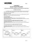
1
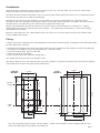
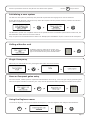
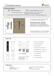
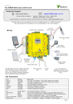
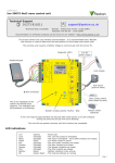
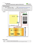
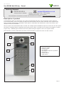
05/11/2012
Paxton
Ins-30201 Net2 Entry - Panel
Technical Support
01273 811011
[email protected]
Technical help is available:
Monday - Friday from 07:00 - 19:00 (GMT)
Saturday from 09:00 - 13:00 (GMT)
Documentation on all Paxton products can be found on our website - http://www.paxton.co.uk/
Description of product
The Net2 Entry panel is a robust door entry panel incorporating both door entry and access control functions.
It is powered using power over Ethernet (PoE) and communicates with the other elements of the system using
IPv6, providing 'plug and play' installation. Each panel is associated with a Net2 Entry control unit which is the
interface to the door hardware.
Only one panel can be associated with a control unit. Multiple panel installations require a control unit for each panel.
The panel is equipped with a keypad and a proximity token reader. A resident can use either the keypad or a token
to gain entry. Installers gain access to the menu options using an engineer code or an engineer token.
Net2 software is used to administer the access control functions. It must be v4.25 or a later version.
6
5
7
8
1.
2.
3.
4.
5.
6.
7.
8.
4
Speaker
Proximity reader
Backlit keypad
LCD display
IR LEDS for night time operation
Microphone
Colour camera
Light sensor
3
1
2
Page 1
Installation
The best height to install the panel is with the camera at eye level. This will allow you to see your visitor's face
clearly even when they are wearing a hood or cap.
To achieve the best camera performance, try to mount the panel facing away from direct sun or a bright light source.
This will also help the user to read the LCD display.
Decide how the units are to be connected. You can either run your own wired network or (with the owner's
permission) share the buildings existing data network. If using the owners network, the system uses IPv6 protocol
and PoE (Power over Ethernet) so the network must support this switch type.
Paxton recommend that the network cable is run to each location and terminated in a network box. A patch
cable should then be used to link the unit to the network. This makes unit replacement or removal for building
maintenance much easier.
Where it is not practical to run a patch cable to the rear of the unit, it can be directly wired to the network cable
via the supplied IDC module.
Fixing
A single hole must be drilled for the single data/power connection. Electrical power is supplied via the data cable (PoE)
from the Net2 Entry controller.
1.
2.
3.
4.
5.
Determine the height for the camera and then mark and drill the cable hole with reference to the Fixing diagram.
Complete the installation of the mounting backbox - Surface or Flush.
Connect the Net2 Entry panel to controller.
Mount the panel in its backbox.
Power up the panel from controller supply (PoE).
The display will ask you to set up an Engineer code.
The panel checks to see if any monitors also exist on the network. Any that are detected will now have the engineer
code loaded and will store the panel ID that called them.
FLUSH
BACKBOX
104 mm
106 mm
℄
Cable
Hole
44 mm
40 mm
80 mm
320 mm
290 mm
55 mm
51 mm
281 mm
130 mm
235 mm
205 mm
℄
196 mm
Camera
Height
30 mm
SURFACE
BACKBOX
21 mm
70 mm
140 mm
The unit is supplied with the surface mount backbox. A flush mount backbox is also available (PN:337-857).
Screws and wall plugs are provided in the fitting kit.
Page 2
SURFACE MOUNT
1. Determine and mark the height and position for the camera.
2. Mark and drill the hole for the network cable (network patch or Cat5). Ensure that the waterproof grommet will
have clearance behind the backbox.
3. Determine the position of the mounting screws, drill the holes and push in the No 8 wall plugs.
4.
5.
6.
7.
8.
9.
Pass the cable through the backbox and secure with the grommet. (A loose grommet is supplied for Cat5 cable)
Secure the backbox to the wall with the screws provided.
If using Cat5, wire this to the IDC connector (see wiring label) and attach the short patch lead.
Connect the cable to the panel.
Locate the panel, top first, into the backbox and secure on the underside with two Torx screws.
The Torx key for the screws should be stored in the control box for future use.
FLUSH MOUNT
The entry panel may be mounted in a flush mount backbox.
1.
2.
3.
4.
5.
6.
Determine and mark the height and position for the camera.
Mark and drill the hole for the network cable (network patch or Cat5).
Ensure that the waterproof grommet will have clearance behind the backbox.
Cut a hole in the wall to accept the backbox as required. Ensure there is clearance for the sliding latch.
Determine the position of the mounting screws, drill the holes and push in the No 8 wall plugs.
Pass the cable through the backbox and secure the grommet. (A loose grommet is supplied for Cat5 cable).
Secure the backbox to the wall with the screws provided. Ensure the sliding latch on the underside is to the right.
7.
8.
9.
10.
If using Cat5, wire this to the IDC connector (see wiring label) and attach the short patch lead.
Fit two Torx screws into the underside of the panel to act as locating pins for the sliding latch.
Connect the cable to the panel.
Locate the panel, top first, into the backbox. While pressing the panel against the backbox, slide the latch to
the left with a flat blade screwdriver, trapping the Torx screws.
11. Fit a Torx screw at the bottom of the backbox to lock the latch.
12. The Torx key for the screws should be stored in the control box for future use.
Page 3
Use the up and down arrows on the panel to view all the menu options.
Use the
X
key to Cancel
Initialising a new system
The first time the system is powered up the panel will request that the Language to be used is confirmed.
It then asks for an Engineer code to be set up. Enter the required code and press the bell key. Confirm the code and
press bell to complete the process.
The Net2 Entry system uses a separate control unit to operate the door. To associate a panel with its control unit, the
Serial Number of the control unit must be entered.
Only one panel can be associated with a control unit. Multiple panel installations require a control unit for each panel.
Calling a Monitor unit
As Monitor units are added to the system, they
will automatically become active. To call a monitor
type in the monitor ID and press the Bell button.
Single Occupancy
When only one monitor ID is in use, pressing the Bell button will call the monitor.
How an Occupant gains entry
For access control, a Net2 system is required for administration. Once set up, a user can gain entry by presenting their
token to the panel. For PIN or Code entry, the # key must be pressed first before pressing the numbers on the panel.
#
Using the Engineer menu
To access the Engineer menu from the default screen press *, enter the Engineer code and press the Bell button.
*
Page 4
Use the up and down arrows on the panel to view all the menu options.
1. Door open time
Use the
X
key to Cancel
from the Engineer menu - Press key 1.
This is the time period that the lock will stay
released once the open door button has been
pressed on a monitor. This value may only be
changed when not administered by Net2.
2. Volume settings
1. Set voice volume
from the Engineer menu - Press key 2
from Volume settings menu - Press key 1
This sets the volume of the entry panel speaker.
Use the up and down arrow buttons to adjust then press Bell.
2. Set keypress tone
from Volume settings menu - Press key 2
This sets the tone that the entry panel will make when a key is pressed.
Press 1. Click
Press 2. Beep
Press 3. Silent
3. Set door open tone
from Volume settings menu - Press key 3
This sets the tone that the entry panel will make while the lock is released.
Press 1. Beep
Press 2. Buzz
Press 3. Silent
3. Call timeout
from the Engineer menu - Press key 3
This is the maximum time period that one call
can last. This ensures that the entry panel is not
held busy if a call is not terminated correctly.
4. View options
from the Engineer menu - Press key 4
1. Allow video without being called
from View options menu - Press key 1
This allows the camera to be viewed at any time even when not being used to grant access.
Press 1. Yes
Press 2. No
2. Allow audio without being called
from View options menu - Press key 2
This allows the microphone to be turned on at any time even when not being used to grant access.
Press 1. Yes
Press 2. No
3. Open the Door without being called
from View options menu - Press key 3
This allows the 'Unlock door' button to be used while viewing with the camera. The visitor does not need to initiate the call.
Press 1. Yes
Press 2. No
Page 5
5. Panel settings
1. Set control unit
from the Engineer menu - Press key 5
from Panel settings menu - Press key 1
This sets the control unit that the Net2 Entry panel is associated with.
Enter the Serial Number of the control unit and then press Bell.
2. Factory reset
from Panel settings menu - Press key 2
This returns the Entry panel to Factory settings
Press 1. Yes
Press 2. No
3. Backlight
from Panel settings menu - Press key 3
This sets when the Entry panel backlight will be on.
Press 1. Always on
Press 2. Never on
Press 3. Only on in low light
4. Video quality
from Panel settings menu - Press key 4
This option slows the video rate to reduce the load on busy networks.
Press 1. Low - busy networks
Press 2. Med - small networks
Press 3. High - private wiring
6. Operating Mode
1. Number only
from the Engineer menu - Press key 6
from Set Operating mode menu - Press key 1
This requires the visitor to enter the number without the assistance of a list.
2. Numbered list
from Set Operating mode menu - Press key 2
This displays the monitor IDs to the visitor as a numeric list with its name which they can scroll or enter the number.
Menu will also respond to numeric input.
3. Text selection
from Set Operating mode menu - Press key 3
This displays the monitor names to the visitor in alphabetical order which they can scroll through and select.
Page 6
7. Engineer Access
1. Set Engineer Code
from the Engineer menu - Press key 7
from Engineer Access menu - Press key 1
This allows the Engineer to change the Engineer code
2. Change Engineer Token
from Engineer Access menu - Press key 2
This allows the engineer to add / change the Engineer token
The engineer can create a token that can be presented to the proximity reader instead of using the engineer code to
gain access to the Engineer Menu.
8. Language
from the Engineer menu - Press key 8
This displays the language options available for this monitor.
9. About
from the Engineer menu - Press key 9
This displays information about the panel. (e.g. the current version number)
Specifications
Dimensions
Electrical
Width
Height
Depth
100 mm
280 mm
30 mm
Min
Power over Ethernet (PoE) power rating
Communication
Ethernet bandwidth requirement
IEEE 802.3af class 0
Min
Max
100kb/s multicast
1Mb/s multicast
per panel during call
100
Panels per system
Features
Max
12.95W
Min
Max
Camera system
Full colour
I/R illumination
Yes
Audio system
Two way
Display
Backlit LCD
125k/Hz
Proximity reader
Environment
Operating temperature
Min
Max
-20 °C
50 °C
IP55
IP Rating
Vandal resistance
The declaration of conformity is available on request. Contact details are provided at:
Paxton tokens
External use
Medium
http://paxton.info/596
Page 7