1
Net2 User Manual
Version 3
ins-188
Date code: 230305
t
Contents
Chapter 1 Introduction........................................ 5
This manual .............................................................................. 5
Manual layout..................................................................................... 5
References to areas of the Net2 program ...................................... 5
Overview – system .................................................................. 6
Overview – Net2 hardware .................................................... 6
Overview – Net2 software ..................................................... 7
Chapter 2 About… ............................................... 9
Net2 software ........................................................................... 9
Net2 software - View options.............................................. 10
Main window ................................................................................... 10
Treeview window ............................................................................ 10
Shortcut window.............................................................................. 10
Toolbar ............................................................................................... 10
Drop down menus ........................................................................... 10
Net2 software – The structure ............................................. 11
The Net2 Server (NetSvr.exe)........................................................ 11
The Net2 User Interface (Net2.exe) .............................................. 11
The databases.................................................................................... 11
System communications ...................................................... 12
Doors – General information .............................................. 13
What are doors? ................................................................................ 13
Doors........................................................................................ 13
Reinstate ............................................................................................ 13
Replace ............................................................................................... 13
Delete ACU ....................................................................................... 14
Detect.................................................................................................. 14
Doors\[Door name] .............................................................. 14
Door name ......................................................................................... 14
Door open time................................................................................. 15
Unlock the door during .................................................................. 15
Apply .................................................................................................. 15
Open door.......................................................................................... 15
Doors\[Door name]\Reader 1 ............................................ 15
Name................................................................................................... 15
Reader type........................................................................................ 15
Keypad ............................................................................................... 15
Card data format .............................................................................. 16
Contents
1
Reader operating mode .................................................................. 16
Timed operating modes.................................................................. 16
Reader action .................................................................................... 17
Doors\[Door name]\Reader 2 ............................................ 17
Doors\[Door name]\Alarm ................................................ 17
Local alarm ........................................................................................ 18
Testing the local alarm ................................................................... 18
Alarm reporting at the PC .............................................................. 18
Do not unlock door when exit button is pressed ..................... 18
Doors\[Door name]\Codes................................................. 19
Doors\[Door name]\Events................................................ 19
Timezones - General information ...................................... 20
What is a timezone?......................................................................... 20
What are timezones used for? ....................................................... 20
Timezones............................................................................... 20
Timezones\[Timezone name]............................................. 21
Adding timeslots.............................................................................. 21
Deleting timeslots............................................................................ 21
Dragging and dropping.................................................................. 21
Start time and End time windows................................................ 21
Copying and pasting ....................................................................... 21
Public holidays................................................................................. 22
Apply .................................................................................................. 22
Access levels – General information ................................. 22
What is an access level? .................................................................. 22
Access levels ........................................................................... 23
Access levels\[Access level name]..................................... 24
Users – General information ............................................... 24
Users – General information ............................................... 25
Users......................................................................................... 25
Departments...................................................................................... 25
Users\[User name] ................................................................ 26
General information........................................................................ 26
Pictures............................................................................................... 26
Access rights...................................................................................... 26
Users\[User name]\Cards ................................................... 27
Lost cards ........................................................................................... 27
Users\[User name]\Other details and Memo ................. 27
Users\[User name]\Events.................................................. 28
Users\[User name]\Current validity ................................ 29
Events – General information ............................................. 29
Events....................................................................................... 30
Event search ...................................................................................... 31
Event filtering................................................................................... 31
Contents
2
Reports – General information ........................................... 32
Reports – Running the default reports.............................. 32
All events (last week, this week, today, yesterday) ................. 32
Expired cards..................................................................................... 32
First and last events......................................................................... 32
Last known position of users ........................................................ 32
List all users ...................................................................................... 32
Who’s been in today........................................................................ 33
Reports – Adding a new report........................................... 33
Standard............................................................................................. 33
Advanced ........................................................................................... 33
Net2 operators – General information .............................. 33
Operator privileges.......................................................................... 33
System engineer ............................................................................... 34
Supervisor ......................................................................................... 34
Card Administrator ......................................................................... 34
Standard (Read only) ...................................................................... 34
Events only ........................................................................................ 34
Net2 operators ........................................................................ 35
Options – General information .......................................... 36
Options\General ................................................................... 36
Week starts on .................................................................................. 36
Desktop reader ................................................................................. 36
The events view will show ............................................................ 36
Default pictures................................................................................ 36
Options\Departments.......................................................... 37
Options\Field names ........................................................... 38
Options\Card types .............................................................. 39
Options\Card data formats................................................. 40
Options\Backup.................................................................... 41
System backup ................................................................................. 41
Event backup .................................................................................... 42
Options\Public holidays ..................................................... 42
Other features......................................................................... 43
Print..................................................................................................... 43
Other features\Import wizard............................................ 43
Other features\Find user ..................................................... 45
Other features\Open door .................................................. 45
Chapter 3 About… (Advanced Features)....... 47
Multiple Workstations ......................................................... 47
Area definitions ..................................................................... 48
Anti-passback......................................................................... 50
Roll call and Muster.............................................................. 52
Fire Alarm Input .................................................................... 54
Contents
3
Cameras ................................................................................... 55
Chapter 4 What if the system is not working?57
Is the problem genuine?....................................................... 57
Simple checks......................................................................... 58
Paxton Access technical helpline ....................................... 59
Chapter 5 Appendix ........................................ 61
Appendix (i) Difference between code and PIN
explained ................................................................................. 61
Appendix (ii) Glossary ....................................................... 62
Appendix (iii) Upgrading to V3........................................ 63
Chapter 5 Specifications ...................................................... 65
Contents
4
Chapter 1 Introduction
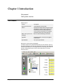
This manual
Net2 system overview
This manual
Manual layout
Section
Description
Net2 system overview
An introduction to the system.
About…
In depth information about all aspects of the
Net2 software. This section is split up into
the different sections of the program i.e.
Doors contains information on everything
found in the Doors icon in the treeview.
What if the system is not
working?
Basic test and faultfinding information.
Appendix
Information that is referred to throughout
the document.
Specifications
Full system specification.
References to areas of the Net2 program
The Net2 software uses a Microsoft Outlook style user interface. Areas of
the Net2 program are referred to throughout this document with Microsoft
Outlook style ‘addresses’. For example Timezones\Working hours refers to
the part of the program shown in this section. References are always
shown in italics.
Chapter 1 Introduction
5
Overview – system
Net2 is a revolutionary system with hardware and software developed
simultaneously to meet the requirements of a modern day access control
system. The hardware uses the latest in microchip technology allowing
unprecedented levels of speed, resilience and cost. The software is based
on the latest Windows interface and is developed to enable powerful
functionality whilst maintaining ease of use.
An access control system is an investment. The Net2 system ensures the
future proofing of that investment in several ways:
• Latest microchip technology offering solid, capable hardware
platform
• Use of FLASH memory allowing easy upgrades
• Software can be extended in functionality with ‘Modules’
• System can be extended with no redundancy of equipment
The system is capable of controlling up to 200 doors and 10,000 users. For
systems larger than this please contact the Paxton Access support
department.
Overview – Net2 hardware
Ease of wiring
Clearly labelled terminals on every access control unit remove the need
for continual referencing to wiring diagrams. Clear colour coding of
reader cables leads to fewer mistakes.
Diagnostic LEDs
An array of LEDs on the control unit indicate the status of key system
features. This will aid commissioning and quick diagnosis of any
problems should they occur.
Chapter 1 Introduction
6
FLASH Memory
FLASH memory in the access control units allows the downloading of
new firmware to the control units from the PC. This will mean that as new
features are added to Net2, systems in the field can be upgraded to allow
the use of the latest software features without any changes to the
hardware.
Open architecture
Relay outputs and digital and analogue inputs allow integration with the
hardware of other systems.
Latest technology
State of the art electronic components create a solid hardware platform,
which is both high performance and compact.
Scaleable architecture
The system will be scaleable. The smallest system will be expandable to
the largest system using the same hardware building blocks and virtually
no redundancy of hardware as the system expands.
Communications
Very high speed and resilient communications offer real time alarm
reporting and the capability for very large systems.
Distributed intelligence
The Net2 single door control units provide full distributed intelligence
down to individual doors. This gives greater system resilience and makes
support and problem diagnosis easier. Also, event information can be
retained when the system is running offline (2,300 events).
Multi-technology
The same control unit will support magstripe (Clock and data), Wiegand
26bit, keypads and proximity, mixed on a single site if required.
Overview – Net2 software
Open architecture
Microsoft Access database allows easy linking of data to other software
systems.
Ease of use
Easy to learn, intuitive user interface working in Microsoft Windows 2000
and Windows XP environments.
Ease of commissioning
Auto detection and numbering of access control units. No DIP switches to
set or binary numbering to worry about, switch on the software and go!
Modular
The software has the capacity for features to be added as and when they
are required. The modular structure enables the user interface to be as
powerful as required whilst remaining simple.
Comprehensive range of features
All the basic features required to control access privileges of users with
respect to time and create reports on the events happening around the
system. Many advanced features have been added in version 2 of the
program, a list of these additional features is included in the Appendix.
Full details of all system features are documented in the About… section.
Chapter 1 Introduction
7
Chapter 1 Introduction
8
Chapter 2 About…
Net2 software
Doors
Timezones
Access levels
Users
Events
Reports
Net2 operators
Options
Other features
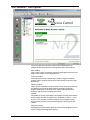
Net2 software
The Net2 software is based on the Microsoft Outlook style user interface.
This provides an excellent graphical interface allowing easy access to all
system features. Windows users will find this style of interface familiar
enabling fast, intuitive learning. Many Windows features such as drag
and drop and right mouse button click have been included in Net2.
Chapter 2 About…
9
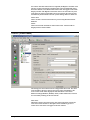
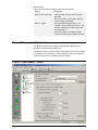
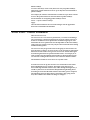
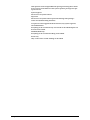
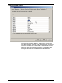
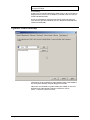
Net2 software - View options
The screen shot shows the three windows of the Net2 software. In
addition to these windows there are drop down menus and a task bar.
Main window
This is where events, user details, settings etc are displayed. The size and
shape of this window can be changed to suit.
Treeview window
This is the Explorer style window that is used to navigate around the
program. This is optional and can be turned on and off in the View drop
down menu.
Shortcut window
This is the bar of shortcuts on the left of the screen. There are shortcuts to
the different areas of the program allowing navigation around the
program without the use of the treeview. This is optional and can be
turned on and off in the View drop down menu.
Toolbar
The toolbar, at the top of the display, has buttons accessing some features
directly (Print, Find user and Open door – for details see About…\Other
features). Also included are Internet Explorer style navigation arrows,
these allow the operator to flip back through areas of the program just
visited.
Drop down menus
The drop down menus feature shortcuts to areas of the program as well as
system settings and configuration options.
Chapter 2 About…
10
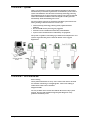
Net2 software – The structure
The Net2 software consists of several components; the Net2 User Interface,
the Net2 Server, the communications engine and various databases. These
are all installed onto a single PC. If you want to be able to control the Net2
system from a remote PC, either over a LAN, WAN, or through the
Internet via VPN, then you will need to purchase Net2 Version 3 software
for additional PC workstations (950-001).
The Net2 Server (NetSvr.exe)
The Net2 Server is an application that controls the sending of data to and
from the control units, and allows operators to connect into the system.
The Net2 Server should be left running at all times, where possible. This
will ensure that an operator can view the latest events as they happen.
Also, some features of Net2 V3 require the server to be running. These
include automatic fire door opening, anti-passback and the validating and
expiring of users validity. If you are using the Additional Workstation
software, to connect into the system from a remote location, the server
must be running.
By default, the server is set to run at start-up, which means that it will be
gathering events from the control units, and will instantly be available
when an operator starts the Net2 User Interface. A Net2 Server icon can be
seen in the bottom right corner of the Windows task bar when the server
is running.
The default location for the server is C:\Program files\Program
Files\Access Control\NetSvr.exe
The Net2 User Interface (Net2.exe)
The Net2 User Interface is a user-friendly program that an operator uses to
change and view system details. The default location for the program is
C:\Program Files\Paxton Access\Access Control\Net2.exe
The databases
The main database is called Net2System.mdb. This database stores all of
the information that is specific to an individual system such as user
details, door details, configuration, timezones etc. It is created the first
time that the Net2 program is run and the default location is C:\Net2
access control. If the Net2System database is lost, corrupted or deleted
then the whole system will have to be reconfigured unless a backup copy
can be reinstated (for information on backup refer to
About…\Options\Backup)
Chapter 2 About…
11
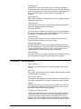
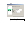
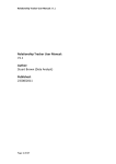
System communications
PC Running Windows 98,
NT4 SP6a, 2000 or XP
Net2System
Net2 User Interface
(Net2.exe)
Net2 Server
(NetSvr.exe)
Net2Events
Communications
Server
(CommsSvr.exe)
NetMsg
COM 1
Up to 200 Net2 Control Units
via RS232-485 converter
COM 2
Up to 200 Net2 Control Units
via RS232-485 converter
COM n
Up to 200 Net2 Control Units
via RS232-485 converter
The number of communication ports allowed depends on the
operating system. Windows 2000 supports up to 256
The diagram shows the basic structure of the Net2 software.
Example 1:
1.
An operator changes a user’s validity using the Net2 User Interface.
2.
When the operator presses the Apply button these changes are sent to
the Net2 Server, which stores them in the Net2System database, and at
the same time, sends an instruction to the Communications Server to
update the control unit. This all happens in a fraction of a second.
Example 2:
1.
A user presents their token and passes through an access point on the
system.
2.
The Communications Server polls the control units at around 20 times
per second (Depending on the number of control units connected), so
will be notified of the event almost immediately. The event is stored
in the Net2Events database, which is linked through the Net2System
database, and then the Net2 Server is notified that there is a new
event.
3.
The Net2 Server then notifies the Net2 User Interface of the new event
and if it is currently viewing events, it will immediately be shown.
Note: Even though there are several steps in each of the examples, actions
and events will appear instantaneous due to the speed of each process.
Chapter 2 About…
12
Doors – General information
What are doors?
The Net2 system is designed to control access through doors. Doors in the
treeview window, refers to the doors controlled by the system. Each
control unit is designed to control a single door.
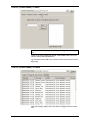
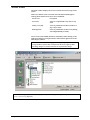
Doors
General information about the control units at each door is shown
including name of the door, serial number of the control unit, the current
version of firmware and the status of the control unit. If the status is OK
then the control unit is communicating with the software correctly.
Reinstate
All system settings and user access rights etc. are stored in the database on
the hard drive of the PC controlling the Net2 system. In addition to this,
information relevant to each individual door is stored at the relevant
control unit. This Distributed intelligence offers greatly increased system
resilience and speed of decision making.
The Net2 software automatically updates the Net2 database AND the
information in the Net2 control units when a change is made. If there has
been a problem with communications, and the information in the control
units is not correct, then the database information can be re-sent by
Reinstating the control units.
There are Advanced features which in addition to re-instating the data,
allow the firmware to be updated as well. This should only be done if the
firmware version is not correct. Under normal circumstances, the firmware
will be upgraded automatically by the Net2 Server as a normal part of the
upgrade process.
The information on the database is always taken as being correct. If
incorrect decisions are being made at the door then check the settings on
the database (i.e. the information displayed in the Net2 software).
Replace
Chapter 2 About…
13
If a control unit fails and needs to be replaced, the Replace wizard is used.
The new control unit must be wired into the system and detected (using
the Detect button). Once detected the control unit will appear in the main
display window. The Replace wizard can now be run and will ask you to
select the new control unit and the one to be replaced. The software will
automatically download the relevant system settings and user details etc.
Delete ACU
This is used if a control unit needs to be permanently deleted from the
database.
Detect
This will search the network for Net2 control units. Those found are
displayed in the main window.
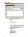
Doors\[Door name]
The settings for each control unit are configured in this screen. The ACU
serial number is shown in the top left corner of the main display. The
lower section of the main display has tabs that allow access to the
different settings (Reader1, Reader2, Alarm, Codes and Events). Sections
are accessed by clicking on the relevant tab.
Door name
When the system is first powered up, the control unit name will be the
same as the serial number. A descriptive name should be given to a
control unit. This name will appear in the list of doors.
Chapter 2 About…
14
Door open time
The door open time is the amount of time that the output relay is switched
for (the amount of time that the locking mechanism is released). The
default setting is 7 seconds. This can be modified within the range 1 to
5000 seconds.
Unlock the door during
This feature allows the user to select a timezone in which the locking
mechanism is released. If the working hours timezone is selected, the door
will be open during working hours. An example of where this may be
useful is where a receptionist is present to greet visitors during office
hours. The main door can be left open so that anybody can walk in. Out
of working hours the door is automatically locked and a valid user card is
required to gain access.
A door can be held open during any timezone. For more information on
timezones refer to About…\Timezones.
Apply
When any changes are made to the door settings the Apply button must be
pressed to commit the changes to the database.
Open door
The open door feature will release the locking mechanism for the door
open time.
Doors\[Door name]\Reader 1
The Reader 1 tab shows the settings corresponding to Reader 1 and
Keypad 1 connected to that control unit.
Name
The default name for reader 1 is [Door name] (IN). The default name for
reader 2 is [Door name] (OUT).
The reader names set here will appear in reports and be used to set access
levels.
Reader type
This should be set to the relevant type of reader.
Setting
Description
None
If no reader is connected.
Paxton reader
If a CARDLOCK or PROXIMITY reader is
connected.
Clock and data
If a non – Paxton clock and data reader is
connected
Wiegand
If a Wiegand reader is connected.
Keypad
This should be set to the relevant type of keypad.
Chapter 2 About…
Setting
Description
None
If no reader is connected.
Paxton keypad
If a TOUCHLOCK keypad is connected.
15
Card data format
Every card enrolled on a Net2 system must have a unique number. The
card data format option allows Net2 to use cards and tokens with a variety
of encoding formats.
The default setting is for the Net2 encoded cards and tokens (random 8
digit number).
Setting
Description
Default
This is for Net2 encoded cards and tokens
(random 8 digit number).
Paxton cards
This is for CARDLOCK and PROXIMITY
cards and tokens (encrypted number).
Bank cards
This allows Net2 to use bank cards.
Refer to About…\Options\Card data formats for more detailed
information.
Reader operating mode
The correct operating mode should be selected from the drop down menu.
Setting
Description
Inactive
There is no reader or keypad connected (or
they are inactive for some other reason).
Card only
Access is granted by swiping a valid user
card.
Card plus PIN
Access is granted by swiping a valid user
card AND entering the relevant PIN.
Card plus code
Access is granted by swiping a valid user
card AND entering a valid code.
Desktop reader
A desktop reader is connected. This reader is
to be used to add users to the system.
PIN only
Access is granted by entering a valid PIN.
Code only
Access is granted by entering a valid code.
Card or PIN
Access is granted by swiping a valid card OR
entering a valid PIN.
Card or code
Access is granted by swiping a valid card OR
entering a valid code.
Card, PIN or code
Access is granted by swiping a valid card OR
entering a valid PIN OR entering a valid
code.
For information on the difference between PIN and code, refer to
Appendix\Difference between code and PIN.
The list of operating modes displayed in the drop down menu is
dependent on the reader type and keypad type settings. For example, if a
keypad is configured without a reader, only Inactive, Code only and PIN
only will be displayed in the drop down menu.
Timed operating modes
This feature allows a different operating mode within a timezone. For
example, card plus PIN may be required outside working hours and card
only within working hours.
To configure this, select the required timezone from the drop down menu.
Select the required operating mode from the other drop down menu.
Chapter 2 About…
16
Reader action
This is the action that will happen when access is granted.
Setting
Description
Relay 1 - door open time
Access granted will open relay 1 for door
open time.
This can be used for temporarily releasing
electric locking mechanisms.
Relay 2 - toggles
Access granted will toggle relay 2. For
example, a valid card will open relay 2. The
relay will remain open until another valid
card is presented.
This can be used for switching an alarm
system on and off, opening shutter doors etc.
Doors\[Door name]\Reader 2
The Reader 2 tab shows the settings corresponding to Reader 2 and
Keypad 2 connected to that control unit.
The default name for reader 2 is [Door name] (OUT). This can be changed.
All settings are set as shown for reader 1. Readers 1 and 2 are configured
separately and can have completely different settings.
Doors\[Door name]\Alarm
Chapter 2 About…
17
There are 4 types of alarm that can be configured for each ACU.
Type of alarm
Description
Requires…
Door forced open
The door is opened without the permission of
the access control system.
Door contact
Door left open
The door is opened with the permission of the
access control system but is not closed within
the specified time.
Door contact
PSU failure
The mains supply to the control unit PSU fails.
If battery backup is fitted then the system will
continue to operate.
Mains fail output on power
supply
Tamper
The control unit enclosure has been opened.
Tamper switch on control
unit enclosure
Each type of alarm has its own tab and is configured in the same way. The
settings for each type of alarm can be different.
Local alarm
On every control unit there is an alarm output. This can be connected to a
bell, sounder, light etc. The local output can be turned on or off for each
type of alarm.
If the local alarm is activated then a delay can be imposed before the
alarm is activated. It can also be configured in a particular way to
distinguish between different alarm events. The alarm can be set to sound
continuously or can be configured manually.
Testing the local alarm
The local alarm can be tested by activating it and silencing it from the PC.
Alarm reporting at the PC
All alarm events are reported at the PC. A delay can be imposed before an
alarm event is sent.
Do not unlock door when exit button is pressed
At first glance, this sounds like a strange ‘feature’. It can however be very
useful under certain circumstances. It allows a door to have a mechanical
exit mechanism, but to be monitored for Door forced alarms. This is
achieved by connecting a PIR sensor to the inside of the door, and wiring
the contacts into the Exit button input. As long as the PIR registers
someone on the inside of the door, when it is opened, it will not raise an
alarm. If however the door is opened without the PIR sensing someone on
the inside of the door, as would be the case if it were being forced open
from the outside, an alarm is raised.
Chapter 2 About…
18
Doors\[Door name]\Codes
Note: The Codes tab only appears if a keypad is configured on the control
unit.
Codes can be simply added and deleted. Codes added in this screen will
only be valid for the individual door.
Up to 50 codes can be valid at any one time. Codes can be between 4 and 8
digits long.
Doors\[Door name]\Events
This screen simply displays the events that have happened at that control
unit.
Chapter 2 About…
19
Timezones - General information
What is a timezone?
Term
Description
Timezone
A series of timeslots.
Timeslot
A start and stop time on a particular day of
the week.
A timezone is made up of several timeslots. A simple example of a
timezone is the default Working hours timezone. This has 5 timeslots:
9am-5.30pm Monday
9am-5.30pm Tuesday
9am-5.30pm Wednesday
9am-5.30pm Thursday
9am-5.30pm Friday
This is a simple example of a timezone. Timezones can have several
timeslots per day (total number of timeslots is 2048 maximum). This
allows for break times, night shifts and more complicated timezones.
Maximum number of timezones is 64.
What are timezones used for?
The Net2 system has many functions that depend on the time and day of
the week. For example, a user can be set to have access at particular times
on particular days of the week. Timezones are used to make this as simple
as possible, i.e. the user can be made valid within a timezone.
Once a timezone is set up, it can be used for any feature requiring a
timezone.
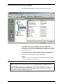
Timezones
The main window displays the timezones that have been setup on the
system.
There are 3 default timezones that cannot be deleted (although the
working hours default timezone can be modified).
Timezone
Description
At no time
At no time on any day of the week
All day, every day
24 hours per day, every day of the week
Working hours
9am-5.30pm Monday to Friday
Timezones can be added, deleted or renamed by either clicking on the
right mouse button or using the buttons at the bottom right corner of the
main display window.
Chapter 2 About…
20
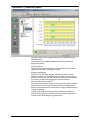
Timezones\[Timezone name]
The main window shows a graphical display of the selected timezone.
Adding timeslots
New timeslots can be added by holding the left mouse button and
dragging the pointer.
Deleting timeslots
Timeslots can be deleted clicking the ‘Delete’ the button in the bottom
right hand corner of the main display window.
Dragging and dropping
Timeslots can be moved by dragging and dropping. This is done by
holding the left mouse button down and moving the pointer whilst the
timeslot is selected. The start and end times of a timeslot can be adjusted
to the nearest 15 minutes by dragging the end of the timeslot.
Start time and End time windows
These appear in the bottom left hand corner of the main display window.
When a timeslot is selected the start and end times are displayed. The
timeslot can be adjusted to the nearest minute using up and down arrows.
Copying and pasting
Clicking on the right mouse button whilst a timeslot is selected will
activate cutting, copying and pasting. An entire sequence of timeslots in
one day can be copied using the copy day feature.
Chapter 2 About…
21
Public holidays
As well as the 7 days of the week, there is an entry for public holidays.
This allows specific timeslots to be set up for days that are nominated as
public holidays.
For example, the Cleaners shift timezone could be set up to allow cleaners
access to the premises between 9am and 11am on public holidays.
For information on configuring public holidays refer to
About…\Options\Public holidays.
Apply
Once the timezone details are correct the changes must be applied for
them to be committed to the database.
Access levels – General information
What is an access level?
An access level is a level of access permissions, i.e. where in a building a
user is allowed. A common requirement of an access control system is to
be able to set different access permissions for different groups of users.
Sometimes the access permissions will be dependant on the time and day
of the week, for example a user may only be allowed into the office during
standard working hours.
An access level may be given the name of the group of users that it is for
(such as factory workers). An access level is set by selecting an appropriate
timezone for each reader. Users given an access level will be able to gain
access during the timezone specified for that reader. For example, if we
want to limit access through the main entrance to during working hours,
we select the working hours timezone next to the main entrance reader.
The maximum number of access levels on a system is 250.
If Areas have been set up, then Access Levels are based on areas rather
than individual doors. For instance, instead of saying that access is
allowed through the Main entrance (In) reader during Working hours, it
would say that access is allowed into Reception during Working hours
(assuming of course that the Main entrance (In) reader goes to reception).
The advantage of this is that if there is more than 1 door going into an
area, then it reduces the number of things to configure.
Chapter 2 About…
22
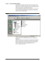
Access levels
The main window displays the access levels that have been setup on the
system.
There are 3 default access levels that cannot be deleted (although the
working hours default access level can be modified).
Access level
Description
At no time
Access is not permitted at any time on any
doors
All day, every day
Access is permitted on all doors, 24 hours a
day, 7 days a week
Working hours
Access is permitted on all doors only during
9am-5.30pm Monday to Friday
Access levels can be added, deleted or renamed by either clicking on the
right mouse button or using the buttons at the bottom right corner of the
main display window.
Note: It is not recommended to apply the all day, every day access level
to large numbers of users. This would prevent the access rights of these
users being changed as a batch when the site requirements change.
Note: You can change the access level for all people in a department by right clicking on the department in the
treeview, and selecting Properties
Chapter 2 About…
23
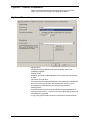
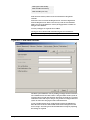
Access levels\[Access level name]
The main window displays the settings for the current access level.
Every reader on the system is displayed. Next to the reader name, a
timezone can be selected from the drop down menu. When a user is given
an access level, they will be permitted through the readers shown, during
the timezones shown.
The screen shot in this section shows that morning cleaners are allowed in
the car park at all times, out of the car park at no time and through all
other doors on the system only during working hours.
Apply
Once the access level details are correct, the changes must be applied for
them to be committed to the database.
NOTE: If areas have been set up, access levels will be set up based on areas instead of a list of individual
doors. For instance, consider the situation where there are 2 doors, Main entrance and Side door, which both
enter into Reception. If areas have not been set up, then you will have 2 entries in the access level
configuration for Main entrance (In) and Side door (In). You will need to individually select a timezone for
each. If areas have been set up, then the single entry Reception will appear in the access level. This can
greatly reduce the complexity of maintaining large sites.
Chapter 2 About…
24
Users – General information
‘Users’ refers to the people that use the access control system. Users are
identified to the system by a card, token or PIN (or a combination of any
of these). Once a user has been identified to the system, a decision can be
made on whether they are permitted or denied access.
Every user that has been entered onto the system has a user record. This
contains information regarding their access permissions, cards/tokens,
PINs and any other details required.
Users
The users on the system are displayed in the main window. If
departments have been configured then these will also be displayed.
Departments
Departments allow users to be grouped. This is particularly useful when
there are a large number of users on the system. Having users grouped
together by department enables quick reporting and viewing of users.
For more information about setting up departments, refer to
About…\Options\Departments.
Chapter 2 About…
25
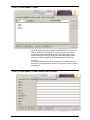
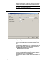
Users\[User name]
General information
Name, telephone number, department and personnel number can be
recorded if required.
Valid from and Valid until; indicate the dates between which the user is
valid. Visitors for example can be configured so that their card
automatically expires after one day. Contractors or temporary staff can be
configured to be valid between certain dates.
The default setting for the Valid from date is the date that the user is
added to the system. This can be changed using the drop down calendar.
The Valid until date is inactive as default. If required it can be marked as
active and a date can be selected from the drop down calendar.
The user can be barred from all doors by pressing the Bar user button.
A users complete record can be deleted by pressing the Delete record
button. This will completely remove the user record from the database.
WARNING - This action cannot be undone.
Pictures
A picture of the user can be imported into the user record. A picture can
be imported by pressing the Get picture button. Bmp, jpg, gif, wmf and
emf formats are supported.
Pictures can be deleted by pressing the Delete picture button.
When a picture is imported into a user record, a copy is made and stored
in C:\Net2 access control\Pictures.
Access rights
The user can be assigned an access level from the drop down list, refer to
About…\Access levels.
Alternatively Individual permissions can be selected. This allows the
exact access of each user to be configured completely independently. This
is often used in sites with few users.
Chapter 2 About…
26
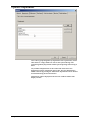
Users\[User name]\Cards
The main display shows the cards that are assigned to the user. As many
cards as required can be assigned to a user (the overall system limit is
10,000 cards). Cards can be added by either entering the card number
manually OR by presenting or swiping the card at the desktop reader.
Cards can be deleted completely by pressing the Delete card button.
Lost cards
If a card is marked as lost it will be automatically invalid on all doors at
all times. If it is presented at any reader on the system an alarm event will
be generated.
Users\[User name]\Other details and Memo
Chapter 2 About…
27
Details can be entered for every user on the system. Default user detail
fields are: Address 1, Address 2, Town, County, Post code, Home
telephone, Home fax, Mobile, E-mail, Position, Start date, Car registration
and Memo.
The 16 user detail fields can be modified as required. For more
information refer to About…\Options\Field names.
Note: Field names can be edited by double clicking on them (unless
disabled in Options).
Users\[User name]\Events
This tab displays the events for that user. This can be useful if trying to
locate a user in a large building, simply go to the user record and see
where they presented their card last. The events in this screen can be
sorted by any of the columns by clicking the left mouse button over the
column header.
Chapter 2 About…
28
Users\User name\Current validity
This tab shows where the user is currently valid. The readers on which the
user is currently valid will be highlighted.
Events – General information
An ‘Event’ is the report of an incident that has occurred on the system. For
example, when a user presents their card and is permitted access at a door,
an event is sent to the PC. The event documents the user concerned, the
reader at which they presented their card, the time and date etc.
The following incidents produce an event:
Chapter 2 About…
Event
Description
User access permitted
A user has been permitted access.
User access denied
A user has been denied access.
Door opened with exit
button
Exit button has been used.
Door opened with
network instruction
Door has been requested open by software.
Operator logon
An operator has logged onto the Net2
software.
Operator Logoff
An operator has logged off of the Net2
software.
ACU online
The control unit is communicating with the
PC.
Control unit reset
The control unit has been reset.
Desktop reader
A card has been presented or swiped at the
desktop reader.
Door forced open
A door has been opened without the
permission of the access control system.
Door left open
A door has been left open for longer than the
specified maximum time.
29
Tamper
The control unit enclosure has been tampered
with.
Mains fail
The mains supply to the control unit has
failed.
Card not valid – card
reported as lost
A card that has been marked as lost has been
used on the system.
ACU not responding
The control unit is not communicating with
the PC.
Operator events
These show system events made by an
operator.
If the PC is switched on, events will be reported almost immediately. If
the PC is switched off the event will be held at the control unit (2,300
event buffer) until the PC is next switched on.
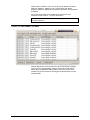
Events
The main display shows the events in date/time order. The most recent
events are displayed at the top.
Date/time, user and location are recorded as well as a description if the
event.
The events are reported in real time. The green and red buttons at the top
left corner of the main display control the flow of events. The red button
will stop the events screen being updated. The green button will allow
events to be reported immediately.
Chapter 2 About…
30
Event search
Events may be searched for keywords. A search can only been performed
when the red button is pressed, i.e. the event screen is not being updated.
The text to search for is entered into the text box at the top of the screen.
Pressing the binocular icon will search for any events containing this text.
The events with matching text will be displayed.
For example, to search for events at the front door type ‘front door’ in the
text box and press the binocular icon.
Event filtering
Events displayed can be filtered by time and type of event.
The time span over which the events appear in the event screen can be
selected from the drop down menu. The options are: Show last hour,
Show today, Show last 7 days and Show all.
The type of event that is displayed in the event screen can be selected
using the icons at the top of the screen. The options are: Show system
events only, Show alarm events only, Show access events only and Show
all event types.
Check the Alarms at top check box, to keep un-acknowledged alarms at
the top of the events screen.
Note: Double clicking an event involving a user will automatically open
their user record. Double clicking an alarm event will give the option to
acknowledge the alarm, changing the icon colour to green.
Chapter 2 About…
31
Reports – General information
Reports can be produced on various aspects of access control system.
There are a number of default reports. These can be run at any time. In
addition to the default reports, reports can be configured by the user.
Once a report is configured the ‘template’ can be saved and used
whenever required.
All reports can be sorted by any of the fields (i.e. by time, by user name)
by clicking on the column headers. Columns can be dragged and dropped
into any order required.
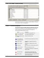
Reports – Running the default reports
Default reports are run by double clicking on the relevant icon.
All events (last week, this week, today, yesterday)
Displays all events that happened during the specified time period.
Displayed fields are: Date/time, User, Where, Event, Details.
Sunday is start of the week as default. This can be changed in
Options\General.
Expired cards
Displays all users with cards that have expired. Displayed fields are: User
name, Access level, Department, Valid from, Expires.
First and last events
Displays a list of all users with the time of their first and last events of
today. Also shown is the difference in hours between the two times.
Last known position of users
Produces a complete list of users along with location of their last event.
Displayed fields are: User name, Date/time, Where, Event, Description.
List all users
Chapter 2 About…
32
Produces a complete list of all users on the system. Displayed fields are:
User name, Access level, Department, Valid from, Expires.
Who’s been in today
Produces a list of the users that have used the system today. Displayed
fields are: Date, User name, Department.
Note: This is not a list of users currently in the building!
Reports – Adding a new report
The report wizard is launched by double clicking the ‘New report’ icon.
The users (or departments) that the report is required for are selected. The
relevant readers are selected from the list. Finally the time period for the
report is selected. The time period can be set in two ways:
Standard
The time scale of the report is selected from the drop down list. Options
include: Today, Yesterday, This week, Last week, This month, Last month,
This year and Last year.
Note: If the report is saved to be used again, a time scale from this menu
should be selected.
Advanced
The time scale of the report can be selected between a particular date
range. Start and end dates can be selected from the drop down calendars.
Net2 operators – General information
The term ‘Net2 operator’ relates to a person that has access to and uses the
Net2 software. There is no limit to the number of Net2 operators allowed.
Operator privileges
Chapter 2 About…
33
Net2 operators can be assigned different privileges allowing them various
levels of access to the features of the system. Operator privileges are split
up into 4 levels:
System engineer
Full access to all system features.
Supervisor
Full access to all system features apart from deleting and replacing a
control unit (and refreshing firmware).
A supervisor cannot upgrade the Net2 software (only System engineer).
Card Administrator
Everything can be viewed but only user records can be edited. Reports can
be run but not created.
Standard (Read only)
Everything can be viewed but nothing can be edited.
Events only
Only events can be viewed. Nothing can be edited.
Chapter 2 About…
34
Net2 operators
The new operator wizard is launched by double clicking on the ‘New
operator’ icon.
Before an operator can be added, they must first be a ‘User’ on the system.
Select the new operator from the drop down list of users. Select the
required operator privilege from the drop down menu. Get the new
operator to type in their password and confirm it.
Note: Only System engineers and Supervisors can create operators.
Supervisors cannot create System engineer operators.
Chapter 2 About…
35
Options – General information
Options can be accessed from the drop down menu at the top of the
screen. All system wide settings are configured in Options.
Options\General
Week starts on
The default setting is that the week starts on Sunday. This can be
modified if required.
Desktop reader
If there is more than one desktop reader on the system, this selects which
is used.
The events view will show
You can specify the maximum number of events which will be loaded into
the events view at any one time. This is particularly useful if you are
connecting into a Net2 System over a slow dial-up connection.
Default pictures
A default picture can be set for each card type (for more information on
card types, refer to About…\Options\Card types). Bmp, jpg, gif, wmf and
emf formats are supported.
A copy of any picture used is stored in C:\Net2 Access Control\Pictures.
Chapter 2 About…
36
Options\Departments
Users can be grouped together by department. This is particularly useful
when there are a large number of users on the system. Having users
grouped together by department enables quick reporting and viewing of
users.
Any number of departments can be created. The name of the new
department is simply entered into the text box. The new department is
added to the list by pressing the Add button. Departments can be deleted
and renamed using the relevant buttons.
Departments will be displayed in the treeview window and the main
display window.
Chapter 2 About…
37
Options\Field names
In the user records there are 16 fields that are user definable. The default
settings for these fields are: Address 1, Address 2, Town, County, Post
code, Home telephone, Home fax, Mobile, E-mail, Position, Start date, Car
registration and Memo. Any of these fields can be modified as required.
There is an option that allows the field names to be changed by double
clicking on them in the user record. This can be enabled/disabled.
Chapter 2 About…
38
Options\Card types
Card types can be created with default settings for:
Valid from
Valid until
Access level
Department
All 16 user definable fields
When adding a new user, simply select the card type and all of the
required fields will be set automatically. This is particularly useful where
lots of new users are being added and many of their details are the same.
To add a new card type press the Add button. Enter the name of the card
type in the text box and press the tick icon to accept. Select the Valid from
date from the drop down calendar. Select the Valid until date from the
drop down list. The simple options for Valid until are:
Card never expires
Card valid today only
Card expires after Monday
Card expires after Tuesday
Card expires after Wednesday
Card expires after Thursday
Card expires after Friday
Card expires after Saturday
Chapter 2 About…
39
Card expires after Sunday
Card valid this month only
Card valid this year only
If advanced is selected, a date can be selected from the drop down
calendar.
Select the access level from the drop down list. Select the department
from the drop down list. Enter values for any of the 16 user definable
fields. Once all of the details are correct, the Apply button commits all
changes to the database.
As many card types as required can be added.
Card types can be deleted and renamed using the relevant buttons.
Note: Visitor is set up as a default card type.
Options\Card data formats
The Net2 system identifies users by reading an 8 digit number from their
user card/token. Each user has to have a unique number for the system to
recognise them. If cards other than the Net2 cards are used, only a portion
of the data on the card may be unique. It is possible to configure the Net2
system to look at the unique part of the card information.
A new card data format can be configured by pressing the Add button.
Enter the name of the new data format in the text box and press the tick
icon to accept. Select the part of the card data that is unique by adjusting
the settings as required.
Chapter 2 About…
40
The settings can be tested by entering a card number (or swiping through
the desktop reader). The way that Net2 will interpret the information is
displayed.
Note: To implement a card data format, it must first be selected in Doors,
refer to About…\Doors\{Door name]\Reader 1.
Card data formats can be deleted and renamed as required.
Options\Backup
System backup
All system settings and user details are stored in an Access 7 database
(Net2System.mdb). If this database is corrupted or deleted, the system
will have to be reconfigured and all user records will be lost. For this
reason it is essential that a backup copy of this file is made on a regular
basis.
The Net2 software creates backup files automatically. A separate copy of
the Net2System.mdb database is made every day the software is used. The
backup file for a day has the date included in the file name (Net2System
YYYYMMDD.mdb). The backup file is created either:
1.
When the application is closed down
OR
2.
At the automatic backup time as set in Options\Backup
If a backup file has already been created for that day, the file will be over
written with the most current version of the database.
The retention period dictates the number of days that the backup files are
kept for.
Chapter 2 About…
41
Note: Backup files should be saved on a different drive to the
Net2System.mdb file.
Event backup
10,000 events are stored in Net2System.mdb. These are the events that are
displayed in the event screen. In addition, 12 months worth of events are
stored in Net2Events.mdb.
Events are automatically archived to the backup folder. The archived
event files are split into individual years (i.e. Net2 Events 1999.mdb and
Net2 Events 2000.mdb).
Options\Public holidays
Certain days can be nominated as public holidays. Days can be added to
the list of public holidays using the drop down calendar.
When a day is nominated as a public holiday, the validity of users will
depend on the public holiday settings in Timezones, refer to
About…\Timezones\[Timezone name].
Chapter 2 About…
42
Other features
Print
The print feature can be accessed from the toolbar at the top of screen and
can be used to print events and reports.
Note: If only part of the events screen/report is required, highlight the
relevant section and press Print. Only the highlighted area will be
printed.
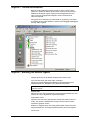
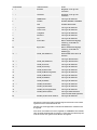
Other features\Import wizard
The import wizard can be accessed from the drop down File menu at the
top of the screen.
Using the wizard it is possible to import user details from an external file.
For example, if a sports club has a database of its users, all of the user
details can be downloaded straight into the Net2 system thus preventing
duplicate data entry.
The user information must be saved as a TXT (Text) or CSV (Comma
Separated Variable) file. Fields can be comma, semi-colon or tab
separated. The fields must be in the order as shown in the table. (Note
that only the first 2 fields are required)
Chapter 2 About…
43
Field number
Net2 field name
Notes
1
*
Surname
Required – Text up to 50
characters
2
*
Firstname
Required – Text up to 50
characters
3
*
Middlename
Text up to 50 characters
4
CardNo
Number 00000001 to 99999999
5
PIN
Number 0001 to 9999
6
*
Department
Text up to 50 characters
7
*
Access Level
Text up to 50 characters
8
Telephone
Text up to 50 characters
9
Extension
Text up to 50 characters
10
Fax
Text up to 50 characters
11
Active date
Date in the default language
format e.g. in the UK it is
dd/mm/yyyy
12
Expiry date
Date in the default language
format e.g. in the UK it is
dd/mm/yyyy
Field1_100 (Address 1)
Default field name shown in
brackets
13
*
Text up to 100 characters
14
*
Field2_100 (Address 2)
Text up to 100 characters
15
*
Field3_50 (Town)
Text up to 50 characters
16
*
Field4_50 (County)
Text up to 50 characters
17
Field5_50 (Post code)
Text up to 50 characters
18
Field6_50 (Home telephone)
Text up to 50 characters
19
Field7_50 (Home fax)
Text up to 50 characters
20
Field8_50 (Mobile)
Text up to 50 characters
21
Field9_50 (Email)
Text up to 50 characters
Field10_50 (Position)
Text up to 50 characters
23
Field11_50 (Start date)
Text up to 50 characters
24
Field12_50 (Car registration)
Text up to 50 characters
Field13_Memo (Notes)
Text up to 65535 characters
(cannot contain field separator).
Field14_50 (Personnel number)
Text up to 50 characters
22
25
*
*
26
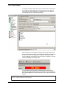
The text file can be browsed to from the import wizard. The correct field
separator must be selected from the list.
The first row can be ignored if it contains the field names. Check the box
if required.
Text can be converted to true text if required (i.e. SMITH becomes Smith).
Only the fields marked with an asterisk (*) in the table are affected by the
‘Convert to true case’ option. Check the box if required.
Chapter 2 About…
44
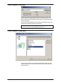
Other features\Find user
The find user wizard can be accessed from the toolbar at the top of the
screen. If there are a large number of users on the system, it may save
time to use the find user wizard. The whole name or any part of the name
can be searched for.
The users are listed alphabetically by surname. Up and Down refer to the
direction the wizard will look for its next match.
Note: When the Users icon is highlighted in the treeview, typing the first
few letters of a users surname will jump to their record.
Other features\Open door
The open door wizard can be accessed from the toolbar at the top of the
screen. Any doors on the system can be made to open for door open time
from the software.
Chapter 2 About…
45
Chapter 2 About…
46
Chapter 3 About… (Advanced Features)
Multiple Workstations
Area definitions
Anti-passback
Roll call and Muster
Fire Alarm Input
Cameras
(The advanced features can be enabled/disabled during the installation process)
Multiple Workstations
The Multiple Workstations feature allows more than one operator to view
and administer a Net2 site. Up to 5 concurrent connections are permitted
at any one time. This means that a receptionist could be issuing cards to
visitors, whilst the administration department are viewing attendance
reports, or the system engineer is updating access level configuration.
Net2 Version 3 software for additional PC workstations (950-001) uses the
latest XML technologies to allow operators to manage a Net2 site from
anywhere in the world. Due to advanced compression methods, there is
virtually no reduction in performance whether an operator is
administering the Net2 system locally, or via VPN (Virtual Private
Network) over the Internet. Using the Net2 Version 3 software for
additional PC workstations also allows an operator to administer more
than one site. A valid TCP/IP connection can be established to the site
using inherent windows Dial-up networking methods, for instance LAN,
WAN direct modem connection and VPN through the Internet.
Chapter 3 What if the system is not working?
47
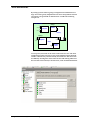
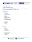
Area definitions
By setting up areas and area groups, configuration and maintenance of
large sites can be greatly simplified. It also allows anti-passback and roll
call reports to be generated on defined areas. Consider the following
example site.
Outside world
Building 2
1
Barrier 1
Stores
Car park
1
1
Stores
Barrier 2
Factory
Building 1
1
Main
entrance
2
1
Building
link
Reception
Sales
1
Meeting
room
2
2
1
Back
door
Meeting
room
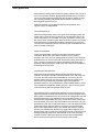
To set up areas, first click on the Areas node on the tree view. The areas
configuration control will now be seen in the right hand panel. Outside
world is a default entry and will already exist in the list. The other areas
are added by entering their name in the text box and clicking Add. Once
the areas have been entered, as shown below, click on Reader definitions.
Chapter 3 What if the system is not working?
48
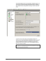
Next, we need to enter which areas the doors go between. In this example,
the main entrance goes from Outside world to Reception. The other doors
are set up in a similar manner.
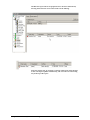
Once the reader definitions have been entered, we can then configure how
the areas are grouped together. Click on Area groups.
The area groups in our example are Building 1 and Building 2, because
they contain sub areas. We can also think of Building 1 and Building 2
forming a larger area group called Building complex. Click Add, and enter
the area group names. The areas can then be dragged and dropped into
the relevant area groups. In the above figure, Sales is being dragged into
the Building 1 area group.
Once the areas have been successfully configured, you will notice that the
Access Level configuration now refers to areas rather than the reader
names.
Chapter 3 What if the system is not working?
49
Anti-passback
Anti-passback is an important feature that greatly enhances the security of
a site. In conjunction with the appropriate door hardware, it prevents the
misuse of cards. Without anti-passback, there would be nothing to stop a
user entering a building and passing their card back to another user,
allowing them to gain access too.
Different situations require different types of anti-passback. Net2
supports 3 types of anti-passback.
Timed Anti-passback
With timed anti-passback, when a user gains access through a reader, the
reader will not allow the same card access for a set duration. This can be
useful where there is no out reader. A car park, for instance, usually only
has access control into the car park. Egress from the car park is not usually
controlled. Setting up timed anti-passback, with duration of 15 minutes,
would prevent a user being able to enter the car park, and hand their card
back to a friend or colleague.
Logical Anti-passback
Logical anti-passback is used on systems where in and out access is
controlled. Because the system knows whether a user is inside a
particular area or not, it can be intelligent about whether access should be
permitted or not. A user must first exit an area before being allowed to reenter. Typically, turn-styles are used in conjunction with logical antipassback. This is particularly suited to the main entrance of a building or
controlling access into clubs.
Timed-Logical Anti-passback
Timed logical anti-passback combines the best of both of the above
methods. As long as a user obeys the anti-passback rules, and swipes out
of an area, they may re-gain access immediately. If, however, the user
tailgates another user out of an area, they will be able to re-gain access,
but only after a specified time period has elapsed. It applies antipassback control to a site, but without the need of administrators to reset a
users permissions should they disobey the rules. After a set time period
of inconvenience, their anti-passback status is reset.
Anti-passback may be enabled under timezone control, which allows for
tight anti-passback control during certain hours, and less stringent control
during others. In addition to this, the system can be configured to reset the
anti-passback status at a specified time. This means that even if a user
disobeyed the anti-passback rules, they can start the next day with a clean
slate. By default, users must obey anti-passback rules, but there is an antipassback tab on the user record, which allows a user to be deselected. This
means that security staff, for instance, can always gain access through
doors, which might otherwise have been barred. For instance, whilst in
pursuit of an unauthorised intruder, they might end up tailgating users
through doors, and it would not be appropriate for them to then be barred
from going through other doors. The same tab on the users record also
contains a button, which when pressed, clears the users anti-passback
status. Their next valid access, sets their location in the system.
Chapter 3 What if the system is not working?
50
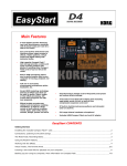
The following diagram shows the anti-passback configuration panel. You
can see that by selecting the Area group Building complex, as defined
under Areas, the system automatically knows that it needs to control Back
door and Main entrance, being the doors which go to and from this area
group.
A door may not be on more than one anti-passback boundary. For
instance, if you set up anti-passback for the Building complex, you would
not be able to also have anti-passback on Building 1, because the Main
entrance would then be used twice. You could, of course, have antipassback control on the car park as well as on the Building complex, as
there are no conflicts of reader.
Note: Anti-passback requires the Net2 Server to be running. If you want to use
anti-passback, it is recommended that the Net2 Server be installed on a dedicated
Windows 2000 or Windows XP machine.
Chapter 3 What if the system is not working?
51
Roll call and Muster
Roll call and Muster is used in the event of a fire, or other incident, to
generate a report of who is in a particular area, and to allow users to report
that they are safe. Muster readers should be pre-defined for each Area
group. Here we can see that if an incident occurs in Building 2, the
personnel should go to the car park, and use the barrier readers as muster
readers.
If an incident should occur, and you wish to create a Roll call report, Click
on the Roll call node from the tree view and click the Create new button.
Select the area where the incident occurred. If you want to create a report
for some time in the past you can do so by clicking Advanced.
A Roll call report will be generated, showing all of the people known to
be in the affected area at the time of the incident.
By setting up the fire-alarm feature, Net2 can automatically generate this
report in the event of a fire.
Note: This feature requires the Net2 Server to be running.
Chapter 3 What if the system is not working?
52
The Roll call report will list all people known to be in the affected area,
showing their last know access. Their status will be Missing.
If the user reports safe, by swiping at a muster reader, their status changes
to Safe. The report updates automatically, and users who are still missing
stay at the top of the report.
Chapter 3 What if the system is not working?
53
Fire Alarm Input
A normally closed fire alarm contact can be wired into any of the 4 inputs
of a control unit (PSU, Tamper, Exit or Contact). In the event of the fire
alarm going off, certain doors may be configured to open. In addition, a
roll call report may be automatically generated.
In this example, we have said that a normally closed output from the fire
alarm system has been wired into the Tamper input (Between Tamper and
0V). If the fire alarm should go off, the Back door, Building link, Main
entrance, Meeting room and Stores doors will open. In addition, a roll call
report for Building 2 will be generated.
You can either click on the ‘Reset fire alarm’ button on the toolbar, or
alternatively, double click the alarm event from the event view. Either of
these acknowledges the fire alarm, and closes any fire doors that may have
opened.
The Net2 Server must be running for this feature to work. Mechanical break glasses, used with fail open
releases, should be installed as a fail-safe backup!
Chapter 3 What if the system is not working?
54
Cameras
Cameras is a feature which allows you to view IP addressable cameras
from within Net2. Eventually this feature will be extended to allow visual
verification as users pass through doors, as well as recording events
triggered by alarm conditions.
Click on Cameras from the tree view and then double click the Add new
item in the right hand panel.
You can then enter the details of the camera. Give it a name, enter the IP
address or URL of the camera, and add any comments you wish.
You may now view the camera by clicking on its name in the tree view.
There are many IP addressable camera’s available. For details please
contact our technical department.
Chapter 3 What if the system is not working?
55
Chapter 3 What if the system is not working?
56
Chapter 4 What if the system is not
working?
Is the problem genuine?
Simple checks
Paxton Access technical helpline
Is the problem genuine?
Experience at first hand that the problem is genuine. Reported faults are
invariably caused by user error. False alarms may be generated by:
•
Incorrect swiping of a magstripe card
•
Worn or damaged magstripe cards
•
Proximity token not presented within read range
•
Incorrect procedure at the PC (changes not being applied for example)
If a genuine problem has been identified, firstly make sure that the
problem can be duplicated. Document the exact nature of the problem;
this will enable your installer and the Paxton Access technical help
department to solve the problem quickly.
Once the problem has been identified, duplicated and documented,
perform the simple checks in the next section.
Chapter 3 What if the system is not working?
57
Simple checks
Firstly, exit the Net2 software and reboot the PC. If problems persist…
Problem
Check…
Events are not reporting in the Events screen
Check the green update button is pressed in the
Events screen. If the red button is pressed, it will
prevent the screen from being updated.
Check that events are actually occurring on the
system.
Check that none of the filters are active on the
Events screen. Select Show all from the drop down
list and press the Show all events icon.
Doors are not opening when cards are presented
Go to a door where the problem has been reported
and ensure that the reader LEDs are on. If they are
not then the reader has no power. Check mains
supply and contact installer.
If the red LED is flashing when a card is presented,
check the validity of the user at the PC.
If the green LED is flashing when a card is
presented, check the connections to the locking
mechanism. Call out installer if required.
User validity is different from that shown on the
software
Check any changes that are made using the
software are applied (press Apply).
Ensure that the Net2 server is running. If not,
double click on C:\Program files\Paxton
Access\Access Control\NetSvr.exe.
Press the Reinstate button in the Doors screen.
This synchronises the information in the database
and the control units.
Control units are showing as not responding in
Doors screen
Check that the RS485/232 converter has power.
Check that the RS485/232 converter is connected to
the COM port of the PC.
Check the mains supply to the control units.
Ensure that the Net2 server is running. If not,
double click on C:\Program files\Paxton
Access\Access ControlNetSvr.exe.
Chapter 3 What if the system is not working?
58
Paxton Access technical helpline
Paxton Access offer a telephone technical help service. This is designed to
assist customers with technical problems. Many technical problems can be
solved by following advice given over the phone, however many
problems will require an installer to attend site.
To qualify for technical support, a valid technical support ID number is
required. This number is generated from the software and can be accessed
by selecting Technical support in the Help drop down menu at the top of
the screen. The technical support ID number will only be valid if the
software had been registered.
To assist our technical help staff to diagnose any problems quickly please
ensure that:
•
The person calling has full details of the problem at first hand
•
The person calling has a working knowledge of the Net2 system
•
Details of the system are at hand i.e. number of doors/users, type of
readers
•
The person calling has read this manual and has followed its
guidelines and simple checks
•
The person calling has the technical support ID number
The Paxton Access technical helpline is available from 7:00am – 7:00pm,
Monday - Friday
0870 6080886
Chapter 3 What if the system is not working?
59
Chapter 3 What if the system is not working?
60
Chapter 5 Appendix
(i)
Difference between code and PIN explained
(ii) Glossary
(iii) Upgrading from V1 to V2
Appendix (i) Difference between code and PIN explained
PIN stands for Personal Identification Number. This is a number that is
specific to an individual user. A user code can be common to many users.
Example of code only: A keypad has two codes to control the access of
1,000 users through an access point. 300 users use one code and 700 use
the other.
Codes are very quick to setup; thousands of users can be given access to
an area if the code is disclosed. Access privileges can be adjusted for
groups of users, where the users are grouped together by a common code.
Example of PIN only: A keypad controls the access of eight users through
a door. Each of the eight users has their own PIN, which they use to gain
access.
Using PINs mean that access rights can be changed for every individual
without affecting other users. PINs also allow users to be identified by the
system for reporting purposes. However, more numbers valid on a keypad
will increase the chances of guessing a correct number. This means that a
non-authorised person can gain access by randomly pressing keys on the
keypad. To reduce these risks to an acceptable level it is necessary to
increase the number of digits in the PIN.
Example of card plus code: A proximity reader and a keypad are used to
control access through a door. A user is required to present their proximity
card to the reader and enter a valid code.
This involves two elements of security – possession and knowledge. The
possession of the card is required AND a valid code has to be known. If
the card is lost it cannot be used on its own. If the code is discovered it
cannot be used without a valid card.
Example of card plus PIN: A magnetic stripe reader and a keypad is used
to control the access through a door. A user is required to swipe their card
and enter their PIN number. Only the combination of that user card AND
that user PIN number is acceptable.
This involves both possession and knowledge but increases security even
further. If a user card is lost it can only be used to gain access when used
with the specific PIN number. For security reasons bank cash machines
use a card plus PIN system.
Specifications
61
Appendix (ii) Glossary
General access control terms
Access control system
An access control system comprises input for identification (e.g. a
keypad or reader), intelligent electronics for decision making and
outputs for operating access point hardware and the access point
hardware itself (e.g. locks, barriers).
Access Control Unit (ACU)
A general term to describe a range of devices which have the control
electronics and intelligence to make the decision to allow access at one or
several points. It will have connectors or cables ready to link to readers,
keypads, locks, etc.
Access level
An access level is a particular level of access privileges with relation to
time.
Anti-passback
The use of anti-passback prevents a second user from being able to gain
access to an area, if a first passes their card back to them.
Areas
When you go through a door, you pass from one area to another.
Examples of areas are Outside world, reception, Stores and Meeting
room.
Area groups
Areas can be grouped together to form area groups. Reception, Sales and
meeting room might form an area group called Building 1.
Cameras
IP addressable cameras are ones which may be viewed from a standard
web browser.
Coercivity
Coercivity relates to the resilience of the encoding of a magnetic stripe
card. Hi coercivity encoded magstripe cards are more resilient to data
corruption than Lo coercivity cards.
Distributed intelligence
In a networked access control system access control units are linked and
communicate with each other or a PC used to control the system.
Distributed intelligence means that the access control units hold user
information and system settings locally. This enables the ACUs to carry
on functioning if communications links are severed.
Door open time
An electric locking device has power supplied/denied to release and
allow access when a valid token is presented. The time period that the
electric release is energised/de-energised is referred to as the door open
time.
Event recording
Access control units may be provided with memory to record events.
Events recorded should include the access point details, date, time and
user ID for each occasion when access is granted. Many other events may
be recorded depending on the system e.g. details of access denied and
alarm events. Where events are recorded the access control unit will be
capable of sending the information to a printer or computer.
Fire doors
Fire doors are doors which can be set up to open automatically in the
event of a fire alarm.
Logical anti-passback
Logical anti-passback protects a system from card misuse by enforcing
that a user leaves an area before being able to re-enter.
Magstripe
Magnetic stripe reading technology – cards with a number encoded on a
magnetic stripe are swiped through a slot on a reader.
Muster reader
A muster reader is a reader which has been specified as one which users
should report safe at in the event of a fire or other incident.
Network system
A system where access control units are linked together by data cable for
the exchange of information between units. The purpose of this is to
provide easier configuration and better management information for
larger and more complex applications. All access points on the system
Specifications
62
can be set up from a single point. The access control units on network
systems record events. Most systems allow for a computer to be
connected to the network to allow control and reporting to be carried out
from a dedicated program.
Photo ID
Where a photograph of the user is printed or attached to their user token
allowing them to be identified.
Proximity
The proximity device is held close to the reader and sends a unique
number by radio signal to the reader.
Roll call
Roll call is a report which lists all people who were in an area group an a
specified time. The users can swipe at a muster reader to register
themselves as safe.
Timed anti-passback
Prevents a card being re-used at the same reader for a certain time period.
Timeslot
A timeslot is a time period on a particular day of week. An example of a
timeslot is between 9am and 5pm on Tuesday.
Timezone
A timezone is a combination of timeslots in a week. An example of a
timezone is Working hours between 9am and 5pm Mon to Fri.
User token
This is a generic term for the devices that users of an access control
system use to identify themselves and gain entry through access points.
User tokens may be magstripe cards, proximity keyfobs, smart cards, etc.
Paxton Access terminology
Proximity ISO card
ISO cards are the same size as standard bank or credit cards. They can be
used with standard card printers for photo ID. They also have a magnetic
stripe that can be encoded for use with other systems such as vending.
Proximity keyfob
Keyfobs are for applications where convenience is important. They are
made of hard plastic and will fit onto a keyring. They can be attached to
car/house keys for reduced losses, hence reducing the cost of replacing
fobs.
Proximity card
Tokens are about credit card size but are thicker. They can be used from
inside wallets or handbags. Adhesive plastic stickers can be applied for
photo ID and the slot in the tokens makes them ideal for use with low
cost badge clips.
Appendix (iii) Upgrading to V3
Verify that the system is communicating correctly
1.
Run the Net2 software logged on as engineer
2.
Go to the Hardware screen and press the Detect button
3.
Check that each ACU has OK reported in the status column
To upgrade
Note: The PC will require re-booting during this procedure
Specifications
1.
Shut down the Net2 software and ensure that the communication
server has also been shut down
2.
Shut down any other programs that are running
3.
Make a backup copy of the folder ‘Net2 Access Control’ –
IMPORTANT
63
4.
Insert the V3 CD ROM and wait for the CD to auto run, alternatively
run setup.exe from the Net2 CD ROM
5.
Follow the on screen prompts
Ready to run
1.
Launch the Net2 software
2.
Go to the Doors screen
3.
The firmware version should now be reported as V3.XX (Build
XXXXXX) and all ACUs should be reported as OK in the status
column
Note: The Net2 communications server will automatically upgrade the
ACU firmware
Note: The communications server will be initialised whenever the
computer starts.
4.
Specifications
Check that events are being reported
64
Chapter 5 Specifications
Net2 software for 200 doors
Maximum number of users
Maximum number of doors
Net2 software for 50 doors
Maximum number of users
Maximum number of doors
Net2 software for 20 doors
Maximum number of users
Maximum number of doors
Reading technologies supported
Individual access rights by access point
Individual time zones
Access levels
Time zones
Read in and read out
Card plus PIN (Personal identification number)
PIN only entry
Number of system operators
System operator privileges
System operator log on to software
Desk top reader
Advance entry of Bank Holidays
Door held / wedged open alarm
Door forced alarm
Instant reports
Printed reports from entire access event history
Data available to other programs
Timed backup of event log
Fail open (fail safe) locks
Door open time
Operates gates, barriers, turnstiles, etc
Network Details
Communications with other control units
Maximum number of control units per data line
Full distributed intelligence
Off line memory in access control units
Access control unit user card capacity
Access control unit user card capacity
Details of supported readers
Magnetic stripe readers
Reader life
Proximity readers
Reader life
Keypads
Keypad life (key presses)
Water resistance
Finishes of CARDLOCK and TOUCHLOCK
Finish of PROXIMITY
Finish of TOUCHLOCK stainless steel
Specifications
10,000
200
10,000
50
10,000
20
All Paxton Access readers: PROXIMITY, CARDLOCK
magnetic stripe, TOUCHLOCK keypads
All users, all access points
All users
Up to 250
Up to 64
Yes
Yes
Yes
unlimited
4 levels
Individual password protection
Provides fast access to user records
Yes
Reported to software and output for local sounder at door
Reported to software and output for local sounder at door
Screen reports on recent events
Yes
Yes - including Word, Excel, Access, etc
Manual backup required
Yes
1 to 5,000 seconds
Yes - all equipment that can be switched by clean relays
RS485 full duplex 115,200 BAUD
200
Yes
2,300 events
10,000 Paxton Access proximity devices or magstripe cards
10,000 bank / credit magstripe cards
CARDLOCK
>1,000,000 swipes
PROXIMITY
Unlimited token reads
TOUCHLOCK membrane or TOUCHLOCK stainless steel
>100,000 membrane or > 1,000,000 for stainless steel
All readers IPX7 (submersible) except membrane keypad IPX5
Black, brass or satin chrome
Black
Stainless steel and satin chrome
65
Network communications
Network communications cable
Maximum length of communications bus
Access Control Unit
Number of doors per control unit
Memory in the event of complete power failure
Backup batteries ensure operation of
Connections in the access control unit for each of the doors
Readers
Keypads
Analogue / digital inputs
5 amp relay outputs (NC, and NO)
1 amp FET controlled output
Reader to access control unit distances
TOUCHLOCK keypad *
TOUCHLOCK keypad stainless steel *
CARDLOCK reader *
PROXIMITY reader*
Access control unit power requirement details
Required supply voltage
Maximum current for access control unit
Maximum current for Paxton Access magstripe readers
Maximum current for Paxton Access proximity readers
Maximum current for Paxton Access keypads
Maximum current for other keypads and readers
Maximum current for locks
Access control unit dimensions
Board size
Recommended minimum space for board in other
manufacturer’s enclosures
Board weight
NETWORK RS485 / 232 communications converter
Size
Communications protocols
Maximum serial cable distance to PC
Low voltage power supply
Desktop reader details
Type of reader
Paxton Access dual technology desktop reader
Size of Paxton Access dual technology desktop reader
Maximum distance to access control unit
Black plastic housing
Size
Features
PSU enclosure size
Details to be confirmed
CAT5 (Screened or unscreened) or Belden® 8723*
1,000m
1
All system settings and user details are retained for 7 days
Entire system except PC - control of access continues
1 or 2 (in, in/out)
1 or 2 (in, in/out)
4 (default uses: exit button, door contact, PSU monitor, tamper)
2 (default use: lock relay and door bell relay)
1 (sinks up to 1A at 12Vdc, default use: local door alarm)
30m
30m
100m
50m
9V to 15V dc
350mA at 12Vdc (allow extra for FET output)
65mA
70mA
45mA
See reader manufacturer’s literature
See lock manufacturer’s literature
102 x 116 x 30mm high
200 x 170mm high
190g
80 x 50 x 20mm
RS232 to PC, RS485 to access control units
7m
250mA 12V dc
The reader type used at the doors on site may be used or:
Reads magstripe cards and Paxton Access proximity devices
160 x 90 x 30 mm
As for other reader distances noted above
175 x 170 x 40mm
Tamper switch, cable tie loops, cable entry knock outs
* All reader and data cables should be segregated from mains power cables to avoid interference. IEE Regulations
and normal good practice should be observed. Belden cables or exact electrical equivalents must be used.
®Windows 2000 and XP, Access, Excel and Word are Registered Trademarks of Microsoft Corporation Inc.
® Belden is a Registered Trademark of Cooper Industries Inc.
Specifications
66