1
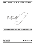
INSTALLATION INSTRUCTIONS
Instrucciones de instalación
Installationsanleitung
Instruções de Instalação
Istruzioni di installazione
Installatie-instructies
Instructions d´installation
CPU Holder for Fusion™ Cart/Stand
Spanish Product Description
German Product Description
Portuguese Product Description
Italian Product Description
Dutch Product Description
French Product Description
FCA650/651
FCA650/651
Installation Instructions
DISCLAIMER
Milestone AV Technologies and its affiliated corporations and
subsidiaries (collectively "Milestone"), intend to make this
manual accurate and complete. However, Milestone makes no
claim that the information contained herein covers all details,
conditions or variations, nor does it provide for every possible
contingency in connection with the installation or use of this
product. The information contained in this document is subject
to change without notice or obligation of any kind. Milestone
makes no representation of warranty, expressed or implied,
regarding the information contained herein. Milestone assumes
no responsibility for accuracy, completeness or sufficiency of
the information contained in this document.
WARNING: Use this mounting system only for its intended
use as described in these instructions. Do not use
attachments not recommended by the manufacturer.
WARNING: Never operate this mounting system if it is
damaged. Return the mounting system to a service center for
examination and repair.
WARNING: Do not use this product outdoors.
WARNING: RISK OF INJURY TO PERSONS! Do not
Chief® is a registered trademark of Milestone AV Technologies.
All rights reserved.
place video equipment such as televisions or computer
monitor on CPU holder.
--SAVE THESE INSTRUCTIONS-IMPORTANT SAFETY INSTRUCTIONS
WARNING: A WARNING alerts you to the possibility of
serious injury or death if you do not follow the instructions.
CAUTION: A CAUTION alerts you to the possibility of
damage or destruction of equipment if you do not follow the
corresponding instructions.
WARNING: Failure to read, thoroughly understand, and
follow all instructions can result in serious personal injury,
damage to equipment, or voiding of factory warranty! It is the
installer’s responsibility to make sure all components are
properly assembled and installed using the instructions
provided.
WARNING: Failure to provide adequate structural strength
for this component can result in serious personal injury or
damage to equipment! It is the installer’s responsibility to
make sure the structure to which this component is attached
can support five times the combined weight of all equipment.
Reinforce the structure as required before installing the
component.
WARNING: Exceeding the weight capacity can result in
serious personal injury or damage to equipment! It is the
installer’s responsibility to make sure the combined weight of
all components located within the CPU holder does not
exceed 25 lbs (11.34 kg) for the FCA650 or 10 lbs (4.5 kg) for
the FCA651.
2
Installation Instructions
FCA650/651
DIMENSIONS
FCA650
5.13
130.2
MAX CPU WIDTH
22.24
565.0
5.40
137.1
15.00
381.0
MAX CPU LENGTH
3.50
88.9
6.20
157.5
15.00
381.0
MAX CPU HEIGHT
16.00
406.4
SECURITY HOLE FOR
5/16" DIAMETER PAD LOCK
INTERNAL SLOTS
FOR TIE DOWN STRAPS
0.38
9.5
PANEL NOT SHOWN FOR CLARITY
FCA651
3.63
92.1
MAX CPU WIDTH
15.74
399.9
3.50
88.9
10.00
254.0
MAX CPU LENGTH
3.90
99.0
3.70
94.0
10.00
254.0
MAX CPU HEIGHT
SECURITY HOLE FOR
5/16" DIAMETER PAD LOCK
11.00
279.4
INTERNAL SLOTS
FOR TIE DOWN STRAPS
0.38
9.5
PANEL NOT SHOWN FOR CLARITY
3
FCA650/651
Installation Instructions
LEGEND
4
Tighten Fastener
Pencil Mark
Apretar elemento de fijación
Marcar con lápiz
Befestigungsteil festziehen
Stiftmarkierung
Apertar fixador
Marcar com lápis
Serrare il fissaggio
Segno a matita
Bevestiging vastdraaien
Potloodmerkteken
Serrez les fixations
Marquage au crayon
Loosen Fastener
Drill Hole
Aflojar elemento de fijación
Perforar
Befestigungsteil lösen
Bohrloch
Desapertar fixador
Fazer furo
Allentare il fissaggio
Praticare un foro
Bevestiging losdraaien
Gat boren
Desserrez les fixations
Percez un trou
Phillips Screwdriver
Adjust
Destornillador Phillips
Ajustar
Kreuzschlitzschraubendreher
Einstellen
Chave de fendas Phillips
Ajustar
Cacciavite a stella
Regolare
Kruiskopschroevendraaier
Afstellen
Tournevis à pointe cruciforme
Ajuster
Open-Ended Wrench
Remove
Llave de boca
Quitar
Gabelschlüssel
Entfernen
Chave de bocas
Remover
Chiave a punte aperte
Rimuovere
Steeksleutel
Verwijderen
Clé à fourche
Retirez
By Hand
Optional
A mano
Opcional
Von Hand
Optional
Com a mão
Opcional
A mano
Opzionale
Met de hand
Optie
À la main
En option
Hex-Head Wrench
Security Wrench
Llave de cabeza hexagonal
Llave de seguridad
Sechskantschlüssel
Sicherheitsschlüssel
Chave de cabeça sextavada
Chave de segurança
Chiave esagonale
Chiave di sicurezza
Zeskantsleutel
Veiligheidssleutel
Clé à tête hexagonale
Clé de sécurité
Installation Instructions
FCA650/651
TOOLS REQUIRED FOR INSTALLATION
3/16" (included)
5/32" (security) (included)
1/8" (included)
PARTS
A (1)
[CPU holder]
(FCA651 shown)
D (4)
5/16-18 x 1/2"
B (1)
[adapter bracket]
E (2)
1/4-20 x 3/8"
F (1)
1/4-20 x 3/8"
C (1)
[accessory bracket]
G (1)
3/16"
H (1)
5/32" (security)
J (1)
1/8"
5
FCA650/651
Installation Instructions
Assembly And Installation
NOTE: The following procedure assumes the Fusion Cart/
(display not shown for clarity)
Stand has already been completely assembled.
IMPORTANT ! : The FCA650/651 has been designed
specifically for Chief’s Fusion™ Series Carts and Stands.
DO NOT attempt to install this CPU holder onto any other
cart or stand!
1.
Remove back cover from cart/stand. (See Figure 1)
2.
Remove column inner cover from cart/stand. (See Figure 1)
3.
Remove side cover from cart/stand by sliding it up the side
channel on the side where the CPU holder will be installed.
(See Figure 1)
(C)
(display not shown for clarity)
5
4
(F)
side covers
column inner
cover
Figure 2
back cover
2
2
1
3
6.
Slide accessory bracket up or down in side channel until
desired mounting height is reached. (See Figure 3)
7.
Tighten set screw (F) to lock bracket in position. (See Figure
3)
8.
Use two 1/4-20 x 3/8" button head cap screws (E) to secure
adapter bracket (B) to accessory bracket (C). (See Figure 3)
1
7
8
Figure 1
4.
Partially install 1/4-20 x 3/8" set screw (F) into accessory
bracket (C). (See Figure 2)
5.
Slide accessory bracket (C) with set screw into side channel
where CPU holder will be installed. (See Figure 2)
6
(B)
Figure 3
6
(E) x 2
Installation Instructions
9.
FCA650/651
Use 5/32" security hex key (H) to remove two security
screws holding side panel to CPU holder (A). (See Figure 4)
10. Slide side panel up to remove it from CPU holder. (See
Figure 4)
14. Use security screws (removed in Step 9) to reattach side
panel to CPU holder (A). (See Figure 6)
15. (Optional) Use padlock (not provided) to provide further
security to CPU holder. (See Figure 6)
(A)
10
side panel
15
13
10
13
9
14
Figure 4
11. Use four 5/16-18 x 1/2" button head cap screws (D) to
secure CPU holder (A) to adapter bracket (B).
(See
Figure 5)
(B)
Figure 6
16. Reinstall back cover to cart/stand.
17. Reinstall inner column cover to cart/stand.
Adjustments
Height Adjustment
(A)
11
1.
Remove side panel and CPU from CPU holder (A).
2.
Loosen set screw (F). (See Figure 7)
3.
Loosen two button head cap screws (E). (See Figure 7)
4.
Adjust height as desired.
5.
Tighten two button head cap screws (E). (See Figure 7)
6.
Reinstall CPU and side panel to CPU holder.
(D) x 4
2
Figure 5
12. Install CPU to CPU holder.
4
WARNING: Exceeding the weight capacity can result in
serious personal injury or damage to equipment! It is the
installer’s responsibility to make sure the combined weight of
all components located within the CPU holder does not
exceed 25 lbs (11.34 kg) for the FCA650 or 10 lbs (4.5 kg) for
the FCA651.
13. Replace side panel back into its original position on CPU
holder (A). (See Figure 6)
3
5
Figure 7
7
FCA650/651
Installation Instructions
USA/International
Europe
Chief Manufacturing, a products division
of Milestone AV Technologies
8800-002263 Rev01
2012 Milestone AV Technologies, a
Duchossois Group Company
www.chiefmfg.com
11/12
Asia Pacific
A
P
F
A
P
F
A
6436 City West Parkway, Eden Prairie, MN 55344
800.582.6480 / 952.225.6000
877.894.6918 / 952.894.6918
Franklinstraat 14, 6003 DK Weert, Netherlands
+31 (0) 495 580 852
+31 (0) 495 580 845
Office No. 1 on 12/F, Shatin Galleria
18-24 Shan Mei Street
Fotan, Shatin, Hong Kong
P 852 2145 4099
F 852 2145 4477